EP0943582A2 - Positionsdetektor für Industriefahrzeuge - Google Patents
Positionsdetektor für Industriefahrzeuge Download PDFInfo
- Publication number
- EP0943582A2 EP0943582A2 EP99105463A EP99105463A EP0943582A2 EP 0943582 A2 EP0943582 A2 EP 0943582A2 EP 99105463 A EP99105463 A EP 99105463A EP 99105463 A EP99105463 A EP 99105463A EP 0943582 A2 EP0943582 A2 EP 0943582A2
- Authority
- EP
- European Patent Office
- Prior art keywords
- switch
- switches
- movable body
- input terminals
- data
- Prior art date
- Legal status (The legal status is an assumption and is not a legal conclusion. Google has not performed a legal analysis and makes no representation as to the accuracy of the status listed.)
- Granted
Links
- 230000005856 abnormality Effects 0.000 claims abstract description 21
- 238000001514 detection method Methods 0.000 abstract description 19
- 230000005484 gravity Effects 0.000 description 3
- 230000007257 malfunction Effects 0.000 description 3
- 230000008602 contraction Effects 0.000 description 1
- 238000000034 method Methods 0.000 description 1
- 230000000717 retained effect Effects 0.000 description 1
- 230000000087 stabilizing effect Effects 0.000 description 1
Images


Classifications
-
- G—PHYSICS
- G01—MEASURING; TESTING
- G01B—MEASURING LENGTH, THICKNESS OR SIMILAR LINEAR DIMENSIONS; MEASURING ANGLES; MEASURING AREAS; MEASURING IRREGULARITIES OF SURFACES OR CONTOURS
- G01B7/00—Measuring arrangements characterised by the use of electric or magnetic techniques
-
- B—PERFORMING OPERATIONS; TRANSPORTING
- B66—HOISTING; LIFTING; HAULING
- B66F—HOISTING, LIFTING, HAULING OR PUSHING, NOT OTHERWISE PROVIDED FOR, e.g. DEVICES WHICH APPLY A LIFTING OR PUSHING FORCE DIRECTLY TO THE SURFACE OF A LOAD
- B66F9/00—Devices for lifting or lowering bulky or heavy goods for loading or unloading purposes
- B66F9/06—Devices for lifting or lowering bulky or heavy goods for loading or unloading purposes movable, with their loads, on wheels or the like, e.g. fork-lift trucks
- B66F9/075—Constructional features or details
- B66F9/0755—Position control; Position detectors
Definitions
- the present invention relates to a detector for detecting the position of forks in industrial vehicles such as forklifts. More specifically, the present invention pertains to a technology for detecting abnormalities in wires that transmit position detection signals.
- a pair of inner masts is supported in a pair of outer masts.
- the inner masts slide up and down in the outer masts and a fork moves with the inner masts.
- various controls are performed in accordance with the position of the fork.
- the fork may be automatically stopped at a position set in advance.
- the rear axle is pivotally supported for improved driving performance. When the fork is raised high and the center of gravity of the vehicle is high, the pivoting movement of the rear axle is restricted to improve stability.
- a reel-type sensor is used to continuously detect the height of fork.
- the reel-type sensor detects the rotation of a reel, which winds and unwinds a wire in accordance with the movement of the fork, to determine the fork height.
- switch-type sensors may be used to intermittently detect the height of the fork.
- a plurality of switch-type detectors is installed on the outer masts, spaced at a certain distance from one another.
- a dog is attached to the inner masts to actuate the switches. The number of detectors turned on in accordance with the height of the inner masts changes. Accordingly, the height of forklift is intermittently detected based on the on-off state of the detectors.
- Whether to continuously detect or intermittently detect the fork height is determined by the kind of control performed. For example, detecting only three height zones, that is, a lower zone, a middle zone, and a high zone may be sufficient. In this case, an inexpensive switch-type sensor is preferred over a more costly reel-type sensor.
- switch-type detectors When switch-type detectors are used, a plurality of switch-type detectors are arranged vertically on the outer masts with a predetermined distance from one another. Wires from each switch-type detector extend along the outer masts. However, when the wires slacken by the movement of the inner masts, the wires may be caught and cut by the inner masts. The cut wires may be short-circuited by touching the masts or the vehicle body. This is likely to cause abnormalities in the electrical system.
- the objective of the present invention is to provide a position detector that detects disorders such as cut wires and short-circuit. Another objective of the present invention is to provide a position detector that has a small number of wires as possible.
- the present invention provides an apparatus for detecting the position of a movable body provided on an industrial vehicle.
- the movable body moves on a predetermined path, and the apparatus detects the passage of the movable body on the path.
- the apparatus has the following structure.
- the apparatus includes a switch or a plurality of switches. Each switch has two states, and each switch is associated with a location on the path. Passage of the movable body by the location changes the state of the associated switch.
- a position judging means having a plurality of input terminals. The number of the plurality of input terminals is more than the number of switches by at least one. Each switch is connected to at least one of the plurality of input terminals. Each of the plurality of terminals is associated with the switch or one of the switches.
- the judging means includes position judging data, wherein a relationship between zones of movement of the movable body and combinations of signal states at the input terminals is defined by the data.
- the judging means judges that the position of the movable body is within one of the zones in accordance with the data when the combination of the signals at the input terminal exists in the data.
- the judging means judges that there is an abnormality when the combination of signals at the input terminal does not exist in the judging data.
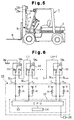
- masts 3 are provided at the front portion of a vehicle body 2 of a forklift 1.
- the masts 3 include a pair of outer masts 3a, which are pivotally supported by the vehicle body 2, and a pair of inner masts 3b, which are located in the outer masts 3a so as to move up and down.
- the inner masts 3b are connected to the top end of a piston rod 4a of a lift cylinder 4.
- Chains (not shown) are installed to chain wheels (not shown), which are supported on the top ends of the inner masts 3b.
- a fork 6 for carrying loads is installed to the front side of the lift bracket 5. The expansion and contraction of the lift cylinder 4 moves the fork 6 up and down by a distance, for example, that is two times the stroke of the inner masts 3b.
- Two height sensors 7 are installed at positions on one of the outer masts 3a.
- the sensors 7 are spaced apart and are at predetermined locations.
- Each sensor 7 outputs either a high level signal or a low level signal according to whether it contacts the inner mast 3b.
- the fork is judged to be in one of three zones, that is, a low zone, a middle zone, and a high zone.
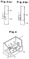
- each height sensor 7 includes an L shaped lever 8, which is pivotally supported in a housing 7a.
- the lever 8 is urged in one rotational direction (counterclockwise in Fig. 4) by a spring 9.
- a switch 10 having a detection member 10a is provided in the housing 7a.
- a detection plate 8b extends from a shaft 8a of the lever 8 in the housing 7a. When the detection plate 8b abuts the detection member 10a, the lever 8 is prevented from pivoting further counterclockwise and is retained at a position perpendicular to the longitudinal axis of the outer mast 3a as shown in Fig. 3(a) and Fig. 4. The lever 8 can pivot clockwise in the state shown in Fig. 4.
- the height sensors 7 are fixed to the rear surface of the outer mast 3a.
- the distal end of the lever 8 extends into the path of the inner mast 3b. Accordingly, the lever 8 is engaged by and pivoted by the inner mast 3b.
- the lever 8 is returned to the horizontal position of Fig. 3(a) by the spring 9.
- the detection plate 8b presses the detection member 10a.
- the mast 3b engages the distal end of the lever 8 and pivots the lever 8 clockwise. This disengages the detection plate 8b from the detection member 10a.
- the switches 10 are contact-type detectors. Each switch 10 is electrically connected to a controller 11 (See Fig. 1), which is located in the vehicle body 2.
- Fig. 1 shows an electrical circuit of the position detector.
- Each switch 10 includes a terminal 20 and first and second contact points 21a, 21b, which are selectively connected to the terminal 20.
- the switch 10 of the lower sensor is referred to as a lower switch SW 1
- the switch 10 of the upper sensor is referred to as an upper switch SW 2 .
- the terminal 20 of the lower switch SW 1 is grounded to the outer mast 3a.
- the first contact point 21a of the lower switch SW 1 is connected to a first input terminal T 1 of the controller 11 by a first signal line SL 1 .
- the second contact point 21b of the lower switch SW 1 is connected to the terminal 20 of the upper switch SW 2 by a connecting line L.
- the first contact point 21a of the upper switch SW 2 is connected to the second input terminal T 2 of the controller 11 by a second signal line SL 2 .
- the second contact point 21b of the upper switch SW 2 is connected to a third input terminal T 3 of the controller 11 by a third signal line SL 3 .
- the controller 11 includes a computer 12 including a central processing unit (CPU) 13 and a memory 14.
- a source voltage V is applied between each input terminal T 1 -T 3 and the CPU 13 through resistors R.
- the upper and lower switches SW 1 , SW 2 selectively ground one of signal lines SL 1 -SL 3 , which are connected the input terminals T 1 -T 3 , respectively, to the outer mast 3a.
- a signal line SL 1 -SL 3 is not grounded, the source voltage V is applied to the corresponding input terminal T 1 -T 3 through a corresponding resistor R, and the potential at the corresponding input terminal T 1 -T 3 is positive.
- a signal line SL 1 -SL 3 is grounded to the outer mast 3a, current flows to the outer mast 3a and the potential at the corresponding input terminal T 1 -T 3 becomes substantially zero.
- the CPU 13 detects the changes of potential in each input terminal T 1 -T 3 as the input signal level changes. In other words, the CPU 13 receives a high level or a low level signal through each input terminal T 1 -T 3 , in accordance with the potential at each input terminal T 1 -T 3 .
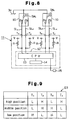
- the memory 14 stores data D1 that determines the relationship between the height of the fork 6 and the input signals at the input terminals T 1 -T 3 .
- the data D1 includes combinations of high (H) and low (L) signals from the input terminals T 1 -T 3 , in accordance with the three height zones of the forklift 6 (low zone, middle zone, high zone).
- the levers 8 of both sensors 7 are engaged and pivoted by the inner masts 3b. This disengages the detection plates 8b of the sensors 7 from the detection members 10a and connects the terminals 20 of the switches SW 1 , SW 2 to a first contact point 21a.
- the combination of the signals from the input terminals T 1 -T 3 is low, high, high, respectively.
- the fork 6 and the inner masts 3b are in the middle zone, only the lever 8 of the lower sensor 7 is disengaged from the inner mast 3b, and the detection plate 8b is connected to the detection portion 10a.
- This connects the terminal 20 of the lower switch SW 1 to the second contact point 21b and connects the terminal 20 of the upper switch SW 2 to the first contact point 21b.
- the combination of the signals from the input terminals T 1 -T 3 is high, low, high, respectively.
- the levers 8 of both sensors 7 are disengaged from the associated inner mast 3b.
- This connects the terminals 20 of the switches SW 1 , SW 2 to the second contact points 21b.
- the combination of the signals from the input terminals T 1 -T 3 is high, high, low, respectively.
- the CPU 13 controls the forklift in accordance with the height of the fork 6. However, the CPU 13 judges which zone (low, middle, and high) the fork 6 is in by reference to the data D1. When the combination of the signals does not correspond to any of the data D1, the CPU 13 judges that there is a cut wire or a short circuit in the electrical system of the position detector.
- the signal line SL 1 of the first input terminal When the signal line SL 1 of the first input terminal is cut, the signal at the first input terminal T 1 is continuously high since the first signal line SL 1 is not grounded. Accordingly, when the fork 6 is in the low zone, the combination of the signals from the input terminals T 1 -T 3 is high, high, high. Then, the CPU 13 judges that there is an abnormality.
- the first signal line SL 1 is short-circuited, that is, when the first signal line SL 1 is cut and connected to the mast 3, the potential at the first input terminal T 1 is continuously low. Accordingly, when the fork 6 is in the middle or high zones, the combination of signals from the input terminals T 1 -T 3 is low, low, high or low, high, low. Then, the CPU 13 judges that there is an abnormality. In this way, it is detected if the first signal line SL 1 is cut or short-circuited.
- the CPU 13 controls the vehicle in accordance with the height of the fork 6. However, when the CPU judges that there is an abnormality, the fork 6 is judged to be in the high zone regardless of its actual position. When the fork is at the highest position, the center of gravity of the vehicle is high, and the rear axle is restricted to stabilize the vehicle. Until a signal reporting correction of the disorder is input, the CPU 13 controls the vehicle as if the fork 6 is at the high position. The CPU 13 activates a reporting device 25 located in the driver's compartment to notify the driver that there is an abnormality. For example, a buzzer or a warning lamp is used as the reporting device 25.
- the present embodiment has the following advantages.
- the present invention will further be embodied as follows. Instead of detecting three positions of the fork 6 by two switches 10, more than four positions may be detected by more than three switches 10. For example, in the second embodiment shown in Fig. 6, (n+1) positions are detected by n (n ⁇ 3) switches SW 1 -SW n .
- the terminal 20 of the lowest switch SW 1 in the lowest sensor 7 is grounded to the outer mast 3a, the first contact point 21a is connected to the input terminal T 1 of the controller 11, and the second contact point 21b is connected to the terminal 20 of the consecutively higher switch SW 2 .
- This series-style connection also applies to SW 2 to SW n .
- the first contact point 21a is connected to the input terminals T 1 -T n of the controller 11, and the second contact point 21b is connected to the terminal 20 of the consecutively higher switch.
- the second contact point 21b is connected to the input terminal T n+1 of the controller 11.
- the number of the signal lines for connecting n switches SW 1 -SW 2 to the controller 11 is n+1.
- the total length of the connecting lines L 1 -L n-1 , which connect each switch SW 1 -SW n is substantially the same as that of the outer mast 3a.
- the number of input terminals for the controller 11 is n+1.
- the memory 14 stores the data D2 shown in Fig. 7.
- (n+1) height zones R 1 -R n+1 which are obtained by dividing the moving range of the fork 6 by (n+1), are set.
- the combinations of signals corresponding to each height R 1 -R n+1 are set.
- the combinations of the signals from the input terminals T 1 -T n are all different in accordance with the zones R 1 -R n+1 . For example, in the height R n , which is nth from the bottom, the signal applied to the input terminal T n is low (L), and the other signals at the other input terminals are all high (H).
- the first contact point 21a and the second contact point 21b may be connected to the input terminals T 1 -T 4 of the controller 11 by corresponding signal lines SL 1 -SL 4 .
- the terminal 20 of each switch 10 is grounded to the outer mast 3a.
- the memory 14 stores the data D3 shown in Fig. 9.
- the combinations of signals under normal conditions are represented by the data D3.
- the CPU 13 judges the zone to which the height of the fork 6 belongs in reference to data D3 by the combination of signals from the input terminals T 1 -T 4 . When the combination of the signals from input terminals T 1 -T 4 is not in the data D3, the CPU 13 judges that there is an abnormality.
- a cut or a short-circuit in any signal line SL 1 -SL 4 or a malfunction of any of the switches SW 1 , SW 2 will be detected.
- Fig. 8 shows two switches 10, however, more than three switches may be used. Further, two positions may be detected by one switch.
- the position detector of the present invention is not limited to detecting the height of a fork.
- the present invention may be used to detect other position parameters. For example, the present invention may be used to detect the inclination angle of the mast 3 or the reach of fork 6 using incremental zones.
- the position detector of the present invention may be configured to measure rotational movement.
- the height sensor 7 may simply be a switch without the lever 8 and the housing 7a. In this case, a cover is preferably provided for protection.
- the switches 10 are not limited to the contact point type, they may also be a non-contact point type. Non-contact point type switches have a similar performance.
- the arrangement of the switches 10 to the mast 3 is not limited to that shown in the figures 1 and 6. In other words, the switch having a grounded terminal 20 may be located at the highest position of the mast 3, and the other switches may be consecutively arranged below it along the mast 3. In this case, the same data in Figs. 2, 7, 9 can be used by arranging the detection plates 8b to depress the associated switch 10 when the lever 8 of the sensor 7 pivots clockwise, which is opposite to the arrangement of Fig. 4.
- the terminal 20 of the lower switch SW 1 does not have to be grounded.
- the first terminal may be wired to a power source, and plus or minus potential may be applied to the terminal 20 of the lower switch SW 1 .
- the present invention may be applied to industrial vehicles other than the forklift 1, such as shovel loader, backhoe, and high elevation vehicle.
- Two sensors (7) are arranged longitudinally on the mast (3).
- Each sensor (7) includes a switch (10) that has two states. The state of each switch can be changed by movement of the fork.
- Each switch (10) is connected to input terminals (T 1 -T 3 ) of a controller (11). The signal at each input terminal changes between two levels in accordance with the state of a corresponding switch (10).
- a memory (14) in the controller (11) stores data that defines the relationship between ranges of movement of the fork (6), or zones, and the combination of the signals.
- the controller (11) judges the height of the fork (6) when the combination of signals corresponds to a combination that exists in the data.
- the controller (11) judges that there is an abnormality when the combination does not exist in the data. This permits detection of malfunctioning switches and a cut and a short-circuited wiring.
Landscapes
- Engineering & Computer Science (AREA)
- Transportation (AREA)
- Structural Engineering (AREA)
- Civil Engineering (AREA)
- Life Sciences & Earth Sciences (AREA)
- Geology (AREA)
- Mechanical Engineering (AREA)
- Physics & Mathematics (AREA)
- General Physics & Mathematics (AREA)
- Forklifts And Lifting Vehicles (AREA)
- Measurement Of Length, Angles, Or The Like Using Electric Or Magnetic Means (AREA)
Applications Claiming Priority (2)
| Application Number | Priority Date | Filing Date | Title |
|---|---|---|---|
| JP6847198 | 1998-03-18 | ||
| JP06847198A JP3178407B2 (ja) | 1998-03-18 | 1998-03-18 | 産業車両における位置検出装置及び産業車両 |
Publications (3)
| Publication Number | Publication Date |
|---|---|
| EP0943582A2 true EP0943582A2 (de) | 1999-09-22 |
| EP0943582A3 EP0943582A3 (de) | 2002-11-20 |
| EP0943582B1 EP0943582B1 (de) | 2004-06-23 |
Family
ID=13374650
Family Applications (1)
| Application Number | Title | Priority Date | Filing Date |
|---|---|---|---|
| EP99105463A Expired - Lifetime EP0943582B1 (de) | 1998-03-18 | 1999-03-17 | Positionsdetektor für Industriefahrzeuge |
Country Status (7)
| Country | Link |
|---|---|
| US (1) | US6138795A (de) |
| EP (1) | EP0943582B1 (de) |
| JP (1) | JP3178407B2 (de) |
| KR (1) | KR100290333B1 (de) |
| CN (1) | CN1125769C (de) |
| DE (1) | DE69918207T2 (de) |
| TW (1) | TW404929B (de) |
Cited By (3)
| Publication number | Priority date | Publication date | Assignee | Title |
|---|---|---|---|---|
| US7287625B1 (en) | 2004-02-19 | 2007-10-30 | Harris Brian L | Forklift safety sensor and control system |
| EP2390222A1 (de) * | 2010-05-27 | 2011-11-30 | Jungheinrich Aktiengesellschaft | Verfahren zum Bereitstellen einer Information über eine aktuelle Hubhöhe und hierfür geeignetes Flurförderzeug |
| US9932213B2 (en) | 2014-09-15 | 2018-04-03 | Crown Equipment Corporation | Lift truck with optical load sensing structure |
Families Citing this family (19)
| Publication number | Priority date | Publication date | Assignee | Title |
|---|---|---|---|---|
| CA2282198C (en) * | 1998-10-07 | 2003-06-10 | Cascade Corporation | Adaptive load-clamping system |
| EP1123835B1 (de) * | 2000-02-10 | 2004-03-03 | Sörensen Hydraulik Zweigniederlassung, Ulfborg, Filial af Sörensen Hydraulik GmbH, Tyskland | Steuereinheit für Ladebordwandsysteme |
| DE10107107A1 (de) * | 2001-02-14 | 2002-08-29 | Putzmeister Ag | Vorrichtung zur Betätigung eines Knickmasts eines Großmanipulators sowie Großmanipulator mit einer solchen Vorrichtung |
| AT500229B1 (de) * | 2004-03-15 | 2008-12-15 | Tgw Mechanics Gmbh | Rechnergesteuerte transportvorrichtung |
| JP4807028B2 (ja) * | 2005-09-30 | 2011-11-02 | 株式会社豊田自動織機 | フォークリフトの走行制御装置 |
| DE102005048355A1 (de) * | 2005-10-06 | 2007-04-12 | Jungheinrich Aktiengesellschaft | Schubmaststapler |
| US20070239312A1 (en) * | 2006-04-10 | 2007-10-11 | Andersen Scott P | System and method for tracking inventory movement using a material handling device |
| FI20065637A0 (fi) * | 2006-10-04 | 2006-10-04 | Jyri Vaherto | Menetelmä trukin tartuntaelimen ohjaamiseksi sekä vastaava järjestelmä ja säätölaitteisto |
| US8230976B2 (en) * | 2008-04-16 | 2012-07-31 | The Raymond Corporation | Pallet truck with calculated fork carriage height |
| DE102010039471B4 (de) * | 2010-08-18 | 2014-02-13 | Robert Bosch Gmbh | Verfahren und Vorrichtung zur Bestimmung einer Hubhöhe einer Arbeitsmaschine |
| CA2832346C (en) | 2011-05-13 | 2015-12-29 | Chep Technology Pty Limited | Pallet truck with lift indicator assembly and associated methods |
| DE102011116645A1 (de) * | 2011-10-21 | 2013-04-25 | Robert Bosch Gmbh | Verfahren und Vorrichtung zur kontinuierlichen Messung der Hubhöhe einer Lasttrageeinrichtung eines Flurförderzeugs |
| CN102564373A (zh) * | 2011-12-27 | 2012-07-11 | 长沙中联消防机械有限公司 | 工程车辆及其轮胎离地检测系统及检测方法 |
| DE102015100534B4 (de) | 2015-01-15 | 2024-03-14 | Linde Material Handling Gmbh | Hubbegrenzungseinrichtung eines Flurförderzeugs |
| KR102549643B1 (ko) | 2015-07-17 | 2023-07-03 | 크라운 이큅먼트 코포레이션 | 산업용 차량을 위한 그래픽 사용자 인터페이스를 갖는 처리 장치 |
| JP6529667B2 (ja) | 2016-01-22 | 2019-06-12 | ヒューレット−パッカード デベロップメント カンパニー エル.ピー.Hewlett‐Packard Development Company, L.P. | 検出区域における粒子凝集の制御を備える流体検出 |
| WO2018098025A1 (en) | 2016-11-22 | 2018-05-31 | Crown Equipment Corporation | User interface device for industrial vehicle |
| CN106934994B (zh) * | 2017-01-21 | 2018-08-17 | 张玉文 | 结合人眼观察与机器信号检测的海上搜救信息传递方法 |
| TWI685165B (zh) * | 2019-04-08 | 2020-02-11 | 大陸商東莞寶德電子有限公司 | 微動開關的訊號偵測電路與方法 |
Family Cites Families (9)
| Publication number | Priority date | Publication date | Assignee | Title |
|---|---|---|---|---|
| US3107750A (en) * | 1962-04-23 | 1963-10-22 | Lipton Products Ltd | Load handling vehicles |
| SE319427B (de) * | 1968-10-16 | 1970-01-12 | K Jacobsson | |
| US4231450A (en) * | 1978-10-23 | 1980-11-04 | White Farm Equipment Company | Overload warning system |
| US4265337A (en) * | 1979-07-16 | 1981-05-05 | Crown Controls Corporation | Fork lift truck speed control dependent upon fork elevation |
| JPS5633399A (en) * | 1979-08-20 | 1981-04-03 | Komatsu Forklift | Cargo work car |
| US4598797A (en) * | 1984-04-13 | 1986-07-08 | Clark Equipment Company | Travel/lift inhibit control |
| JPH0549793A (ja) * | 1991-08-26 | 1993-03-02 | Sanyo Electric Co Ltd | 脱水洗濯機 |
| US5749696A (en) * | 1992-07-23 | 1998-05-12 | Scott Westlake | Height and tilt indicator for forklift truck |
| US5791440A (en) * | 1996-05-13 | 1998-08-11 | The Raymond Corporation | Speed limiting method and apparatus for lift truck |
-
1998
- 1998-03-18 JP JP06847198A patent/JP3178407B2/ja not_active Expired - Fee Related
-
1999
- 1999-03-12 US US09/267,317 patent/US6138795A/en not_active Expired - Fee Related
- 1999-03-17 DE DE69918207T patent/DE69918207T2/de not_active Expired - Fee Related
- 1999-03-17 TW TW088104170A patent/TW404929B/zh not_active IP Right Cessation
- 1999-03-17 CN CN99104110A patent/CN1125769C/zh not_active Expired - Fee Related
- 1999-03-17 KR KR1019990008942A patent/KR100290333B1/ko not_active Expired - Fee Related
- 1999-03-17 EP EP99105463A patent/EP0943582B1/de not_active Expired - Lifetime
Cited By (3)
| Publication number | Priority date | Publication date | Assignee | Title |
|---|---|---|---|---|
| US7287625B1 (en) | 2004-02-19 | 2007-10-30 | Harris Brian L | Forklift safety sensor and control system |
| EP2390222A1 (de) * | 2010-05-27 | 2011-11-30 | Jungheinrich Aktiengesellschaft | Verfahren zum Bereitstellen einer Information über eine aktuelle Hubhöhe und hierfür geeignetes Flurförderzeug |
| US9932213B2 (en) | 2014-09-15 | 2018-04-03 | Crown Equipment Corporation | Lift truck with optical load sensing structure |
Also Published As
| Publication number | Publication date |
|---|---|
| KR100290333B1 (ko) | 2001-05-15 |
| KR19990077961A (ko) | 1999-10-25 |
| DE69918207D1 (de) | 2004-07-29 |
| JP3178407B2 (ja) | 2001-06-18 |
| US6138795A (en) | 2000-10-31 |
| JPH11263600A (ja) | 1999-09-28 |
| CN1229054A (zh) | 1999-09-22 |
| EP0943582A3 (de) | 2002-11-20 |
| DE69918207T2 (de) | 2005-08-11 |
| CN1125769C (zh) | 2003-10-29 |
| TW404929B (en) | 2000-09-11 |
| EP0943582B1 (de) | 2004-06-23 |
Similar Documents
| Publication | Publication Date | Title |
|---|---|---|
| US6138795A (en) | Position detector for industrial vehicles | |
| US5143386A (en) | Automatic leveling system | |
| AU726980B2 (en) | Capacity data monitor | |
| US6611746B1 (en) | Industrial vehicle with a device for measuring load weight moment and a method therefor | |
| US6776249B2 (en) | Industrial truck steered by a tiller | |
| CN111517248B (zh) | 一种agv叉车货物到位检测机构及其agv叉车 | |
| US5424713A (en) | Overhead obstruction detector for a vehicle | |
| JPH07242398A (ja) | 荷役車両の安定度報知装置 | |
| EP1868904A2 (de) | Verstellbarer stromabnehmeraufbau für ein gewerbliches fahrzeug | |
| EP0671346B1 (de) | Mi Sicherheitssystem versehenes Müllsammelfahrzeug | |
| CN220723495U (zh) | 适用于窄巷道的工业车辆 | |
| JP3185744B2 (ja) | 産業車両における位置検出装置及び産業車両 | |
| US3771667A (en) | Moment monitoring system for boom-cable type cranes | |
| EP4245716A1 (de) | Stabilitätssystem | |
| US20250282589A1 (en) | Forklift truck | |
| GB2355244A (en) | Fork-lift truck auto-balancing system | |
| JP2943262B2 (ja) | コンバイン等の姿勢制御装置 | |
| WO2018231134A1 (en) | A clamping device for a forklift and a forklift having such a clamping device | |
| IL104928A (en) | Tire deflation warning system | |
| US20250083939A1 (en) | Aerial lift for working at height, control method and assembly comprising such an aerial lift | |
| US5979915A (en) | Cargo balancing system for a cargo truck | |
| JPH0724394Y2 (ja) | ブーム作業車の検出器異常検出装置 | |
| SU921910A1 (ru) | Сигнализатор наличи преп тствий перед транспортным средством | |
| JPH04267407A (ja) | 無人フォークリフトの走行安全装置 | |
| JPS58167213A (ja) | 産業車両における車軸固定装置 |
Legal Events
| Date | Code | Title | Description |
|---|---|---|---|
| PUAI | Public reference made under article 153(3) epc to a published international application that has entered the european phase |
Free format text: ORIGINAL CODE: 0009012 |
|
| 17P | Request for examination filed |
Effective date: 19990317 |
|
| AK | Designated contracting states |
Kind code of ref document: A2 Designated state(s): AT BE CH CY DE DK ES FI FR GB GR IE IT LI LU MC NL PT SE |
|
| AX | Request for extension of the european patent |
Free format text: AL;LT;LV;MK;RO;SI |
|
| RAP1 | Party data changed (applicant data changed or rights of an application transferred) |
Owner name: KABUSHIKI KAISHA TOYOTA JIDOSHOKKI |
|
| PUAL | Search report despatched |
Free format text: ORIGINAL CODE: 0009013 |
|
| AK | Designated contracting states |
Kind code of ref document: A3 Designated state(s): AT BE CH CY DE DK ES FI FR GB GR IE IT LI LU MC NL PT SE |
|
| AX | Request for extension of the european patent |
Free format text: AL;LT;LV;MK;RO;SI |
|
| RIC1 | Information provided on ipc code assigned before grant |
Free format text: 7B 66F 9/24 A, 7B 66F 9/075 B |
|
| 17Q | First examination report despatched |
Effective date: 20030117 |
|
| AKX | Designation fees paid |
Designated state(s): DE FR GB |
|
| GRAP | Despatch of communication of intention to grant a patent |
Free format text: ORIGINAL CODE: EPIDOSNIGR1 |
|
| GRAA | (expected) grant |
Free format text: ORIGINAL CODE: 0009210 |
|
| GRAS | Grant fee paid |
Free format text: ORIGINAL CODE: EPIDOSNIGR3 |
|
| AK | Designated contracting states |
Kind code of ref document: B1 Designated state(s): DE FR GB |
|
| REG | Reference to a national code |
Ref country code: GB Ref legal event code: FG4D |
|
| REG | Reference to a national code |
Ref country code: IE Ref legal event code: FG4D |
|
| REF | Corresponds to: |
Ref document number: 69918207 Country of ref document: DE Date of ref document: 20040729 Kind code of ref document: P |
|
| ET | Fr: translation filed | ||
| PLBE | No opposition filed within time limit |
Free format text: ORIGINAL CODE: 0009261 |
|
| STAA | Information on the status of an ep patent application or granted ep patent |
Free format text: STATUS: NO OPPOSITION FILED WITHIN TIME LIMIT |
|
| 26N | No opposition filed |
Effective date: 20050324 |
|
| PGFP | Annual fee paid to national office [announced via postgrant information from national office to epo] |
Ref country code: GB Payment date: 20090311 Year of fee payment: 11 |
|
| PGFP | Annual fee paid to national office [announced via postgrant information from national office to epo] |
Ref country code: DE Payment date: 20090313 Year of fee payment: 11 |
|
| PGFP | Annual fee paid to national office [announced via postgrant information from national office to epo] |
Ref country code: FR Payment date: 20090316 Year of fee payment: 11 |
|
| GBPC | Gb: european patent ceased through non-payment of renewal fee |
Effective date: 20100317 |
|
| REG | Reference to a national code |
Ref country code: FR Ref legal event code: ST Effective date: 20101130 |
|
| PG25 | Lapsed in a contracting state [announced via postgrant information from national office to epo] |
Ref country code: FR Free format text: LAPSE BECAUSE OF NON-PAYMENT OF DUE FEES Effective date: 20100331 |
|
| PG25 | Lapsed in a contracting state [announced via postgrant information from national office to epo] |
Ref country code: DE Free format text: LAPSE BECAUSE OF NON-PAYMENT OF DUE FEES Effective date: 20101001 |
|
| PG25 | Lapsed in a contracting state [announced via postgrant information from national office to epo] |
Ref country code: GB Free format text: LAPSE BECAUSE OF NON-PAYMENT OF DUE FEES Effective date: 20100317 |