EP0943350B1 - Séringue préremplie - Google Patents
Séringue préremplie Download PDFInfo
- Publication number
- EP0943350B1 EP0943350B1 EP19990200711 EP99200711A EP0943350B1 EP 0943350 B1 EP0943350 B1 EP 0943350B1 EP 19990200711 EP19990200711 EP 19990200711 EP 99200711 A EP99200711 A EP 99200711A EP 0943350 B1 EP0943350 B1 EP 0943350B1
- Authority
- EP
- European Patent Office
- Prior art keywords
- barrel
- syringe
- plunger
- stopper
- needle
- Prior art date
- Legal status (The legal status is an assumption and is not a legal conclusion. Google has not performed a legal analysis and makes no representation as to the accuracy of the status listed.)
- Expired - Lifetime
Links
Images
Classifications
-
- A—HUMAN NECESSITIES
- A61—MEDICAL OR VETERINARY SCIENCE; HYGIENE
- A61M—DEVICES FOR INTRODUCING MEDIA INTO, OR ONTO, THE BODY; DEVICES FOR TRANSDUCING BODY MEDIA OR FOR TAKING MEDIA FROM THE BODY; DEVICES FOR PRODUCING OR ENDING SLEEP OR STUPOR
- A61M5/00—Devices for bringing media into the body in a subcutaneous, intra-vascular or intramuscular way; Accessories therefor, e.g. filling or cleaning devices, arm-rests
- A61M5/178—Syringes
- A61M5/28—Syringe ampoules or carpules, i.e. ampoules or carpules provided with a needle
- A61M5/284—Syringe ampoules or carpules, i.e. ampoules or carpules provided with a needle comprising means for injection of two or more media, e.g. by mixing
-
- A—HUMAN NECESSITIES
- A61—MEDICAL OR VETERINARY SCIENCE; HYGIENE
- A61M—DEVICES FOR INTRODUCING MEDIA INTO, OR ONTO, THE BODY; DEVICES FOR TRANSDUCING BODY MEDIA OR FOR TAKING MEDIA FROM THE BODY; DEVICES FOR PRODUCING OR ENDING SLEEP OR STUPOR
- A61M5/00—Devices for bringing media into the body in a subcutaneous, intra-vascular or intramuscular way; Accessories therefor, e.g. filling or cleaning devices, arm-rests
- A61M5/178—Syringes
- A61M5/31—Details
- A61M5/3129—Syringe barrels
- A61M5/3134—Syringe barrels characterised by constructional features of the distal end, i.e. end closest to the tip of the needle cannula
-
- A—HUMAN NECESSITIES
- A61—MEDICAL OR VETERINARY SCIENCE; HYGIENE
- A61M—DEVICES FOR INTRODUCING MEDIA INTO, OR ONTO, THE BODY; DEVICES FOR TRANSDUCING BODY MEDIA OR FOR TAKING MEDIA FROM THE BODY; DEVICES FOR PRODUCING OR ENDING SLEEP OR STUPOR
- A61M5/00—Devices for bringing media into the body in a subcutaneous, intra-vascular or intramuscular way; Accessories therefor, e.g. filling or cleaning devices, arm-rests
- A61M5/178—Syringes
- A61M5/31—Details
- A61M2005/3103—Leak prevention means for distal end of syringes, i.e. syringe end for mounting a needle
- A61M2005/3104—Caps for syringes without needle
-
- A—HUMAN NECESSITIES
- A61—MEDICAL OR VETERINARY SCIENCE; HYGIENE
- A61M—DEVICES FOR INTRODUCING MEDIA INTO, OR ONTO, THE BODY; DEVICES FOR TRANSDUCING BODY MEDIA OR FOR TAKING MEDIA FROM THE BODY; DEVICES FOR PRODUCING OR ENDING SLEEP OR STUPOR
- A61M5/00—Devices for bringing media into the body in a subcutaneous, intra-vascular or intramuscular way; Accessories therefor, e.g. filling or cleaning devices, arm-rests
- A61M5/178—Syringes
- A61M5/31—Details
- A61M5/3129—Syringe barrels
- A61M2005/3132—Syringe barrels having flow passages for injection agents at the distal end of the barrel to bypass a sealing stopper after its displacement to this end due to internal pressure increase
-
- A—HUMAN NECESSITIES
- A61—MEDICAL OR VETERINARY SCIENCE; HYGIENE
- A61M—DEVICES FOR INTRODUCING MEDIA INTO, OR ONTO, THE BODY; DEVICES FOR TRANSDUCING BODY MEDIA OR FOR TAKING MEDIA FROM THE BODY; DEVICES FOR PRODUCING OR ENDING SLEEP OR STUPOR
- A61M5/00—Devices for bringing media into the body in a subcutaneous, intra-vascular or intramuscular way; Accessories therefor, e.g. filling or cleaning devices, arm-rests
- A61M5/178—Syringes
- A61M5/31—Details
- A61M5/3129—Syringe barrels
- A61M5/3137—Specially designed finger grip means, e.g. for easy manipulation of the syringe rod
- A61M2005/3139—Finger grips not integrally formed with the syringe barrel, e.g. using adapter with finger grips
-
- A—HUMAN NECESSITIES
- A61—MEDICAL OR VETERINARY SCIENCE; HYGIENE
- A61M—DEVICES FOR INTRODUCING MEDIA INTO, OR ONTO, THE BODY; DEVICES FOR TRANSDUCING BODY MEDIA OR FOR TAKING MEDIA FROM THE BODY; DEVICES FOR PRODUCING OR ENDING SLEEP OR STUPOR
- A61M5/00—Devices for bringing media into the body in a subcutaneous, intra-vascular or intramuscular way; Accessories therefor, e.g. filling or cleaning devices, arm-rests
- A61M5/178—Syringes
- A61M5/31—Details
- A61M5/32—Needles; Details of needles pertaining to their connection with syringe or hub; Accessories for bringing the needle into, or holding the needle on, the body; Devices for protection of needles
- A61M5/3202—Devices for protection of the needle before use, e.g. caps
Definitions
- the present invention generally relates to syringes, and more specifically relates to a prefillable syringe made of a low extractable ion glass, which is particularly suited for being prefilled with substances sensitive to pH shift such as for example water for injection.
- Prefillable glass syringes are well known to those skilled in the art and typically include an elongate barrel having opposed proximal and distal ends and at least one chamber therebetween for receiving a substance such as a fluid.
- a substance such as a fluid.
- syringes there are two types of syringes, i.e., one type in which one end of the barrel is formed to include a tip portion and the other end is formed to include a flange portion and a second type in which both ends of the barrel remain basically unformed in comparison to the first type. Examples of the first type of such syringes having a single chamber are disclosed in U.S. Patent Nos.
- the preamble of claim 1 is based on the disclosure of said US 4,235,235 .
- the syringe is made of a low extractable ion glass having a sodium content of 4% or less.
- the syringe of the present invention includes an elongate barrel having a proximal end and a distal end, with at least one chamber formed between the ends.
- a plunger is sealably disposed within the barrel and movable with respect thereto, and sealing means is sealably disposed approximate the distal end of the barrel, with at least one substance sensitive to pH shift pre-filled in the chamber.
- the barrel is made of a low extractable ion glass having a sodium content of 4% or less, whereby over an extended period of time, the pH of the substance disposed in the chamber of the barrel is maintained within a desirable range.
- the substance is water for injection which has a pH in the range of 5 to 7.
- the range of pH can be maintained over a period of time of at least 24 months.
- the prefillable syringe of the present invention includes a generally cylindrical barrel in the shape of a hollow cylinder made of a low extractable ion glass with an open front end, a plunger, sealably disposed within the barrel and movable with respect thereto, a cylindrical stopper, having an outside diameter which is slightly larger than an inside diameter of the barrel and including means which seal the front end of the barrel, and a needle holder, including a collar which is attached in sealing relationship to the front end of the barrel, a neck for sealable attachment to an injection needle, the neck having a rotationally symmetric rear face which includes an aperture which functions to conduct fluid to the needle, and a hollow, internally cylindrical shaft having a rear end which is sealably connected to the collar and a front end which is sealably connected to the neck, wherein the inner walls of the shaft and the rear face of the neck define one or more slots which extend from the rear end of the shaft to the aperture.
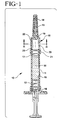
- the prefillable syringe of the present invention is illustrated in FIGS. 1-6 , and generally includes the designation 10.
- the syringe 10 of the present invention includes an elongate barrel or cylinder 11, in which a plunger 12 is provided on one end (the open proximal end) while the other end includes a needle-guard 14 (the distal end), with at least one hollow chamber 15 formed between the proximal and distal ends for receiving a substance.
- the needle-guard 14 keeps the syringe as well as the needle sterile during storage.
- the plunger can be moved by means of a plunger rod, which is secured to the plunger, for example, by screwing.
- the barrel has a fingergrip 16, which is secured to the barrel according to the so-called snap-cap principle.
- the fingergrip preferably consists of slightly resilient material, for example plastics.
- the barrel is manufactured from a low extractable ion glass material, the details of which are discussed hereinbelow.
- the fingergrip is a flangelike part of the barrel projecting radially outwards.
- other constructions known to those skilled in the art are possible.
- a stopper 17, which closes the barrel, is situated in the end of the barrel remote from the plunger.
- the plunger and the stopper are manufactured from an elastic material, preferably rubber of a pharmaceutical quality.
- the injection needle 13 is secured to the barrel by means of a needle holder 18.
- the needle holder has a neck 19, which holds the needle, a shaft 20 and a collar 21.
- the needle holder is preferably manufactured from slightly resilient material, which, however, has resistance to deformation for example, plastics and is secured to the end of the barrel by means of a snap-cap construction.
- the needle holder may be secured to the barrel by means of a screwed or adhesive connection or, when the barrel also comprises a collar, by means of a clamping ring; in the latter embodiment the needle holder may also be flanged around a collar of the barrel.
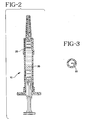
- One or more slots 22 are recessed in the inner wall of the shaft 20 and the rear face of the neck. This is shown in detail in FIG. 3 which is a cross-sectional view through the shaft of the needle holder taken on the line III-III of FIG. 1 and viewed in the direction of the needle.
- One slot is shown in FIG. 3 however more slots may be provided in the needle holder.
- the slot or slots extend into the rear end of the cannula.
- the slots may be parts of a circle, as shown in FIG. 3 , but other shapes are also possible, provided the size is such that sufficient injection liquid can be readily passed through; this is achieved if the diameter of the slot or the overall cross-section of the slots is at least as large as that of the cannula.
- the shaft of the needle holder is constructed so that when the stopper slides axially forward, it is received, with friction, by the shaft; therefore, apart from the slots recessed in the shaft, the inside diameter of the shaft is approximately as large as that of the barrel 11.
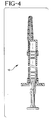
- the shaft of the needle holder is slightly longer than the stopper so that the part 23 of the slot(s) adjoining the barrel is free when the stopper is moved forward against the rear wall of the neck of the needle holder. This is shown clearly in FIG. 2 in which the syringe of FIG. 1 has been activated, that is, moved in the position in which it is ready for administering an injection. In this position the injection liquid can reach the cannula without hindrance via the slots.
- the needle protector may be constructed to also serve as a plunger rod. In that case, prior to the administration of an injection, the needle protector is removed from the needle and secured at the other end of the syringe to the plunger.
- a syringe comprising a needle protector has a safety member, which indicates whether the needle protector has previously been removed.
- a safety member in the form of a cap is described, for example, U.S. Patent No. 3,995,630 .
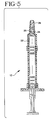
- the needle is eccentric to the barrel.
- Such a construction is sometimes desired in syringes having a large barrel diameter.
- the syringe is not stored with a needle in position.
- the needle is positioned on the neck 24 of the needle holder by means of a needle hub.
- a so-called Luer cone is preferably used for this connection.
- aperture 25 in the neck of the needle holder is closed on the outside by a protective cap 26, which ensures the sterility of the syringe as well as the needle holder.
- Slot 22 recessed in the needle holder projects into the end of the neck aperture.
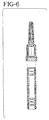
- FIG. 6 shows a two-part embodiment of the syringe.
- the needle holder with injection needle may also be constructed as a needle holder with a Luer cone; in that case the needle is supplied separately.
- the connection of needle holder to barrel is shown as a snap-cap construction.
- each end of the barrel comprises a flange projecting radially outwards and forming one assembly with the barrel; on the rear side the flange forms a finger grip, on the front side it forms a connection for the needle holder.
- the barrel is preferably symmetrical on two sides.
- the end face of the stopper directed rearwardly and the end face of the plunger directed forwardly are both preferably rotationally symmetrical and complementary in order to minimize the residual volume of medicine.
- both faces are substantially flat.
- the front face of the stopper and the rear face of the neck of the needle holder, apart from the slot or slots recessed in said rear face, are preferably complementary surfaces; in this preferred embodiment of the syringe the quantity of medicine remaining in the syringe after the injection also is as small as possible.
- the syringe embodying the present invention may also comprise a so-called “final filter” which serves to stop undesirable material such as "particulate matter", if any, present in the injection liquid.
- a filter is preferably placed on the rear side in the duct in the neck of the needle holder, for example, in a cavity recessed for this purpose between the needle and the rear face of the neck.
- the glass including sodium in the range of 4% or less may be utilized.
- other ions may be considered either alone or in combination with other ions, such as for example potassium, calcium and the like.
- the composition may include Cerium Oxide to provide irradiation stability with respect to coloration.
- the syringe would be sterilizable by irradiation, e.g., by gamma, electron beam, x-ray or the like, which would be advantageous over other sterilization processes where areas of difficulty to reach by the sterilization agent exist.
- the syringe 10 may be assembled and pre-filled by any suitable means, including those disclosed, for example, in U.S. Patent Nos. 5,279,585 (Balkwill ), 5,531,255 (Vacca ), 5,519,984 (Veussink et al. ), 5,373,684 (Vacca ), 5,207,983 (Liebert et al. ), 4,718,463 (Jurgens , Jr. et al.), and 4,628,969 (Jurgens, Jr. et al. ), and PCT Application No. WO 94/13328 (Hagen) .
Claims (7)
- Seringue (10) comprenant :◆ un barillet allongé (11) comprenant une extrémité proximale et une extrémité distale avec au moins une chambre (15) formée entre les deux extrémités ;◆ un piston (12) disposé hermétiquement à l'intérieur dudit barillet et pouvant être déplacé par rapport à ce dernier ;◆ un dispositif d'étanchéité (17) disposé hermétiquement à proximité de ladite extrémité distale dudit barillet ;◆ au moins une substance sensible au changement de PH préremplie dans ladite chambre,caractérisée en ce qui :ledit barillet (11) est constitué de verre ionique à faible extraction ayant une teneur en sodium de 4 % ou moins, moyennant quoi, après une longue durée, le PH de ladite substance située dans ladite chambre dudit barillet est maintenu dans une plage souhaitée.
- Seringue selon la revendication 1, dans laquelle ladite substance est de l'eau à injecter.
- Seringue selon la revendication 2, dans laquelle le PH de ladite eau à injecter est compris dans la plage allant de 5 à 7.
- Seringue selon la revendication 3, dans laquelle la plage de valeurs du PH est maintenue pour une période d'au moins douze mois.
- Seringue pouvant être préremplie selon l'une quelconque des revendications 1 à 4, dans laquelle ledit dispositif d'étanchéité comprend :◆ un bouchon cylindrique (17) dont le diamètre extérieur est légèrement plus grand qu'un diamètre intérieur du barillet et qui comprend un dispositif permettant de sceller l'extrémité avant du barillet ;◆ la seringue comprenant en outre :◆ un porte-aiguille (18) comprenant une bague (21) fixée de façon étanche à l'extrémité avant du barillet, un col (19) pour une fixation hermétique à une aiguille d'injection (13), le col comprenant une face arrière comprenant une ouverture servant à conduire un fluide vers l'aiguille, ainsi qu'une tige interne et creuse (20), comprenant une extrémité arrière qui est hermétiquement raccordée à la bague et une extrémité avant qui est hermétiquement raccordée au col ; les parois internes de la tige et la face arrière du col définissant une ou plusieurs fentes (22) s'étendant depuis l'extrémité arrière de la tige jusqu'à l'ouverture.
- Seringue pouvant être préremplie selon la revendication 5, dans laquelle une face arrière du bouchon (17) est orientée vers le piston (12), une face avant du piston est orientée vers le bouchon, et lesdites faces sont symétriques et complémentaires de façon rotative.
- Seringue pouvant être préremplie selon la revendication 5, dans laquelle une face avant du piston (12) est orientée vers le bouchon, une face arrière du bouchon est orientée vers le piston, et lesdites faces sont toutes les deux des surfaces planes.
Applications Claiming Priority (2)
| Application Number | Priority Date | Filing Date | Title |
|---|---|---|---|
| US7797898P | 1998-03-13 | 1998-03-13 | |
| US77978P | 1998-03-13 |
Publications (2)
| Publication Number | Publication Date |
|---|---|
| EP0943350A1 EP0943350A1 (fr) | 1999-09-22 |
| EP0943350B1 true EP0943350B1 (fr) | 2009-02-18 |
Family
ID=22141129
Family Applications (1)
| Application Number | Title | Priority Date | Filing Date |
|---|---|---|---|
| EP19990200711 Expired - Lifetime EP0943350B1 (fr) | 1998-03-13 | 1999-03-10 | Séringue préremplie |
Country Status (3)
| Country | Link |
|---|---|
| EP (1) | EP0943350B1 (fr) |
| JP (1) | JPH11347124A (fr) |
| DE (1) | DE69940412D1 (fr) |
Family Cites Families (7)
| Publication number | Priority date | Publication date | Assignee | Title |
|---|---|---|---|---|
| US3967759A (en) * | 1971-11-11 | 1976-07-06 | Mpl, Inc. | Syringe assembly with contained pop-out elastic plug seal |
| NL180634C (nl) * | 1977-12-23 | 1987-04-01 | Duphar Int Res | Injectiespuit alsmede naaldhouder hiervoor. |
| EP0191508B1 (fr) * | 1985-02-07 | 1989-04-12 | Duphar International Research B.V | Seringue |
| JPH07206472A (ja) * | 1994-01-12 | 1995-08-08 | Nippon Electric Glass Co Ltd | 医薬用ホウケイ酸ガラス |
| DE4430710C1 (de) * | 1994-08-30 | 1996-05-02 | Jenaer Glaswerk Gmbh | Borsäurearmes Borosilikatglas und seine Verwendung |
| JP3208525B2 (ja) * | 1995-01-05 | 2001-09-17 | 電気化学工業株式会社 | ヒアルロン酸ナトリウム溶液注射剤および注射用容器 |
| JP3306796B2 (ja) * | 1995-01-26 | 2002-07-24 | 大成化工株式会社 | 薬液が予備充填された注入筒向けガラスカートリッジ |
-
1999
- 1999-03-10 DE DE69940412T patent/DE69940412D1/de not_active Expired - Lifetime
- 1999-03-10 EP EP19990200711 patent/EP0943350B1/fr not_active Expired - Lifetime
- 1999-03-12 JP JP11066135A patent/JPH11347124A/ja active Pending
Also Published As
| Publication number | Publication date |
|---|---|
| EP0943350A1 (fr) | 1999-09-22 |
| JPH11347124A (ja) | 1999-12-21 |
| DE69940412D1 (de) | 2009-04-02 |
Similar Documents
| Publication | Publication Date | Title |
|---|---|---|
| US6027481A (en) | Prefillable syringe | |
| JPH0412990Y2 (fr) | ||
| EP0191508B1 (fr) | Seringue | |
| EP0071288B1 (fr) | Seringue hypodermique | |
| US4235235A (en) | Syringe | |
| US3895633A (en) | Large capacity syringe | |
| EP0606429B1 (fr) | Cartouche d'injection a deux chambres | |
| EP0713404B1 (fr) | Seringue aspirante jetable autoprotection | |
| US4900304A (en) | Solid preparation administering instrument | |
| EP1675632B1 (fr) | Seringue thermoplastique a faibles substances extractibles et capuchon pour la pointe | |
| EP1123713B1 (fr) | Serinque à usage unique | |
| EP0826385B1 (fr) | Ensemble seringue | |
| US4581023A (en) | Hypodermic syringe assembly | |
| US8226630B2 (en) | Method of using prefilled, single dose, one time use self-destructing, auto-disabling safety syringe | |
| IL106250A (en) | Safety tube | |
| CN213852500U (zh) | 可预填充的容器 | |
| US4581015A (en) | Multimedication syringe | |
| AU3873799A (en) | Syringe assembly | |
| EP0943350B1 (fr) | Séringue préremplie | |
| CN111670059B (zh) | 预填充式注射器和对预填充式注射器进行灭菌的方法 | |
| JP4095162B2 (ja) | 容器兼用注入装置 | |
| JPH1033674A (ja) | 注射器 | |
| JPH06154324A (ja) | ガスケット |
Legal Events
| Date | Code | Title | Description |
|---|---|---|---|
| PUAI | Public reference made under article 153(3) epc to a published international application that has entered the european phase |
Free format text: ORIGINAL CODE: 0009012 |
|
| AK | Designated contracting states |
Kind code of ref document: A1 Designated state(s): CH DE FR GB LI NL |
|
| AX | Request for extension of the european patent |
Free format text: AL;LT;LV;MK;RO;SI |
|
| RIN1 | Information on inventor provided before grant (corrected) |
Inventor name: MANSOUR, FRANCOIS Inventor name: BARRELLE, LAURENT |
|
| 17P | Request for examination filed |
Effective date: 20000218 |
|
| AKX | Designation fees paid |
Free format text: CH DE FR GB LI NL |
|
| 17Q | First examination report despatched |
Effective date: 20071026 |
|
| R17C | First examination report despatched (corrected) |
Effective date: 20071120 |
|
| GRAP | Despatch of communication of intention to grant a patent |
Free format text: ORIGINAL CODE: EPIDOSNIGR1 |
|
| GRAS | Grant fee paid |
Free format text: ORIGINAL CODE: EPIDOSNIGR3 |
|
| GRAA | (expected) grant |
Free format text: ORIGINAL CODE: 0009210 |
|
| AK | Designated contracting states |
Kind code of ref document: B1 Designated state(s): CH DE FR GB LI NL |
|
| REG | Reference to a national code |
Ref country code: GB Ref legal event code: FG4D |
|
| REG | Reference to a national code |
Ref country code: CH Ref legal event code: EP |
|
| REF | Corresponds to: |
Ref document number: 69940412 Country of ref document: DE Date of ref document: 20090402 Kind code of ref document: P |
|
| PG25 | Lapsed in a contracting state [announced via postgrant information from national office to epo] |
Ref country code: NL Free format text: LAPSE BECAUSE OF FAILURE TO SUBMIT A TRANSLATION OF THE DESCRIPTION OR TO PAY THE FEE WITHIN THE PRESCRIBED TIME-LIMIT Effective date: 20090218 |
|
| NLV1 | Nl: lapsed or annulled due to failure to fulfill the requirements of art. 29p and 29m of the patents act | ||
| REG | Reference to a national code |
Ref country code: CH Ref legal event code: PL |
|
| PLBE | No opposition filed within time limit |
Free format text: ORIGINAL CODE: 0009261 |
|
| STAA | Information on the status of an ep patent application or granted ep patent |
Free format text: STATUS: NO OPPOSITION FILED WITHIN TIME LIMIT |
|
| 26N | No opposition filed |
Effective date: 20091119 |
|
| PG25 | Lapsed in a contracting state [announced via postgrant information from national office to epo] |
Ref country code: LI Free format text: LAPSE BECAUSE OF NON-PAYMENT OF DUE FEES Effective date: 20090331 Ref country code: CH Free format text: LAPSE BECAUSE OF NON-PAYMENT OF DUE FEES Effective date: 20090331 |
|
| REG | Reference to a national code |
Ref country code: FR Ref legal event code: PLFP Year of fee payment: 18 |
|
| REG | Reference to a national code |
Ref country code: FR Ref legal event code: PLFP Year of fee payment: 19 |
|
| REG | Reference to a national code |
Ref country code: FR Ref legal event code: PLFP Year of fee payment: 20 |
|
| PGFP | Annual fee paid to national office [announced via postgrant information from national office to epo] |
Ref country code: GB Payment date: 20180226 Year of fee payment: 20 Ref country code: DE Payment date: 20180219 Year of fee payment: 20 |
|
| PGFP | Annual fee paid to national office [announced via postgrant information from national office to epo] |
Ref country code: FR Payment date: 20180220 Year of fee payment: 20 |
|
| REG | Reference to a national code |
Ref country code: DE Ref legal event code: R071 Ref document number: 69940412 Country of ref document: DE |
|
| REG | Reference to a national code |
Ref country code: GB Ref legal event code: PE20 Expiry date: 20190309 |
|
| PG25 | Lapsed in a contracting state [announced via postgrant information from national office to epo] |
Ref country code: GB Free format text: LAPSE BECAUSE OF EXPIRATION OF PROTECTION Effective date: 20190309 |