EP0942890B1 - Adaptation of section lengths of a printing line - Google Patents
Adaptation of section lengths of a printing line Download PDFInfo
- Publication number
- EP0942890B1 EP0942890B1 EP97952887A EP97952887A EP0942890B1 EP 0942890 B1 EP0942890 B1 EP 0942890B1 EP 97952887 A EP97952887 A EP 97952887A EP 97952887 A EP97952887 A EP 97952887A EP 0942890 B1 EP0942890 B1 EP 0942890B1
- Authority
- EP
- European Patent Office
- Prior art keywords
- web
- printing
- cycle lengths
- length
- Prior art date
- Legal status (The legal status is an assumption and is not a legal conclusion. Google has not performed a legal analysis and makes no representation as to the accuracy of the status listed.)
- Expired - Lifetime
Links
Images

Classifications
-
- B—PERFORMING OPERATIONS; TRANSPORTING
- B65—CONVEYING; PACKING; STORING; HANDLING THIN OR FILAMENTARY MATERIAL
- B65H—HANDLING THIN OR FILAMENTARY MATERIAL, e.g. SHEETS, WEBS, CABLES
- B65H23/00—Registering, tensioning, smoothing or guiding webs
- B65H23/04—Registering, tensioning, smoothing or guiding webs longitudinally
- B65H23/18—Registering, tensioning, smoothing or guiding webs longitudinally by controlling or regulating the web-advancing mechanism, e.g. mechanism acting on the running web
- B65H23/188—Registering, tensioning, smoothing or guiding webs longitudinally by controlling or regulating the web-advancing mechanism, e.g. mechanism acting on the running web in connection with running-web
- B65H23/1882—Registering, tensioning, smoothing or guiding webs longitudinally by controlling or regulating the web-advancing mechanism, e.g. mechanism acting on the running web in connection with running-web and controlling longitudinal register of web
- B65H23/1886—Synchronising two or more webs
-
- B—PERFORMING OPERATIONS; TRANSPORTING
- B65—CONVEYING; PACKING; STORING; HANDLING THIN OR FILAMENTARY MATERIAL
- B65H—HANDLING THIN OR FILAMENTARY MATERIAL, e.g. SHEETS, WEBS, CABLES
- B65H23/00—Registering, tensioning, smoothing or guiding webs
- B65H23/04—Registering, tensioning, smoothing or guiding webs longitudinally
-
- B—PERFORMING OPERATIONS; TRANSPORTING
- B65—CONVEYING; PACKING; STORING; HANDLING THIN OR FILAMENTARY MATERIAL
- B65H—HANDLING THIN OR FILAMENTARY MATERIAL, e.g. SHEETS, WEBS, CABLES
- B65H2511/00—Dimensions; Position; Numbers; Identification; Occurrences
- B65H2511/50—Occurence
- B65H2511/51—Presence
- B65H2511/512—Marks, e.g. invisible to the human eye; Patterns
-
- B—PERFORMING OPERATIONS; TRANSPORTING
- B65—CONVEYING; PACKING; STORING; HANDLING THIN OR FILAMENTARY MATERIAL
- B65H—HANDLING THIN OR FILAMENTARY MATERIAL, e.g. SHEETS, WEBS, CABLES
- B65H2701/00—Handled material; Storage means
- B65H2701/10—Handled articles or webs
- B65H2701/18—Form of handled article or web
- B65H2701/186—Several articles or webs processed together
- B65H2701/1864—Superposed webs
Definitions
- the present invention relates to a method for control or regulation of a period length of at least one printing path, which is a periodically repeating with the period length Has patterns, and one for performing such Device suitable for the method.
- a method and a corresponding device can be found in document EP-A-0 463 213.
- printing web extends here to any for processing by means of printing machines or finishing machines suitable web of any material.
- printing machines come for example Sheets of paper-like material and in particular Paper webs into consideration.
- the Period length of the printing web (register length) is here by the processing period length of the respective processing station determined, for example by the circumferential length of the Printing cylinder of a rotary printing machine.
- a print path already structured by sections must be one subsequent processing station "in phase” in any case are supplied, d. H. on the one hand, the frequency, with which the sections of the printing web into the processing station run equal to their processing frequency, and on the other hand is through the processing station at any time the processing period the relative position of the sections the printing path (register).
- register control which ensures "in-phase” feeding of the printing web, by the "phase”, i.e. H. the location of the sections on the Print path relative to the processing station in a particular one Time within the processing period, before the processing station is measured and depending on the measurement result the processing frequency of the processing station accordingly something is reduced or enlarged.
- a printing web first becomes a Roll is wound up to later be unwound from this roll and to be further processed (off-line finishing), as is often necessary for economic reasons, so the period length of the orbit can become unpredictable Change manner, for example depending on the storage period, storage temperature or humidity. Can too the period length vary within the same web roll, for example if after a certain storage period a freshly printed web roll in this web changes the moisture profile in the radial direction.
- a method for control or regulation a period length of at least one along a track current and one in the web running direction with the Period length showing a periodically repeating pattern Printing path is suggested, taking one to achieve a desired one Period length of the printing web at the beginning of the web running section more or less moisturized.
- the invention is based on the finding that the length of a section on a printing path or the period length change by moistening this print web, in general can enlarge. Knowing the relationship between the Degree of moistening of the printing web and the resulting Changing the length of a section is therefore possible set the desired period length of the printing path. In particular it is possible to change the period lengths of different print paths, which should be merged, to adapt to each other, so that these tracks are merged into register can do what was previously not possible with off-line finishing.
- the period length adapts the printing webs to one another, if necessary, adjusts to one another.
- the period lengths of the different printing paths must be the same be or correspond to each other in such a way that they are in proportion integers.
- the printing webs Have sections whose section lengths differ from printing web to differentiate printing web, but the sections all printing webs each from one or more, adjacent subsections more uniform Length are composed.
- the period lengths the different printing paths are not adjusted, but adapted to each other, such that the lengths of the to Sub-sections to be covered exactly aligned become.
- the current period lengths of these printing webs determined and depending on the determined period lengths the respective desired period lengths or target period lengths specifies.
- the desired period lengths or Target period lengths individually to the originally available Period lengths of the print paths to be merged adjusted.
- the Print path with the comparatively largest value of the current one Period length at the beginning of the railway line is not or only very little moisturized.
- the period lengths of the printing paths are to be aligned with each other, so this becomes the printing web with the largest value of the current period length at the beginning the track.
- the period lengths of the printing webs but to adapt to each other, such that each corresponding subsections of the printing web sections of different lengths brought to the same subsection length will be the printing web with the greatest value of current subsection length at the beginning of the track his.
- dampening rollers can be tangential Strip the passing printing web and wet it, whereby the degree of wetting by means of the speed of rotation of the rollers or changing the web wrap angle is adjustable.
- direct spraying of the printing web is preferred, whereby a particularly smooth and easy way to controlling application of a dampening medium to the printing web is possible.
- the efficiency and uniformity of humidification is increased even further if you have an electrical Field created in the spray area.
- This electric field can, for example, lead to the fact that the printing web in Spray area electrically charges and thus the humidification medium attracts.
- the device according to the invention comprises a moistening device for the printing web as well as one to the dampening device connected control unit that controls the humidifier to achieve the desired period length or the target period length.
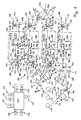
- the device shown comprises four essentially identically constructed railroad tracks 101-104, along their respective a printing web drawn from a printing web roll 110 111-114 is running.
- the precise registration of these four Lanes 111-114 is particularly problematic because of it are webs of different roles, d. H. Not to split partial webs of one and the same web, but to Paths that come together as part of an off-line finishing should be processed further and accordingly not period lengths that are precisely matched or varied (Register lengths).
- the device shown in Fig. 1 is used to measure the period lengths P1-P4 of the four printing paths 111-114 on a uniform Period length P 'at the end of the railway lines 101-104 bring to.
- Each of the lanes 111-114 runs from the respective one Printing web roll 110 successively in the direction of arrow 115 a first measuring device 128 'for measuring its current one Period length at the beginning of the web run, a first web drive device 120 for pulling the web from the respective Roller 110, a humidifier 122 for controlled Moisten the web, a compensator in the form of a Print web storage 124, which has a variable print web length stores, a second web drive device 126 and one second measuring device 128 for measuring the end of the web running section existing period length P1'-P4 'and the relative Position of the sections on the respective web in the longitudinal direction of the web (Passer).
- the lanes are merged in the area of the deflection rollers 144 on the right side of FIG. 1.
- control unit 130 which signals from the just receives mentioned components or outputs signals to them.
- each the period length of the Web is measured and this web then through the humidifier 122 more or less humidified accordingly is going to be one for all at the end of railroad tracks 101-104 to obtain four lanes 111-114 of uniform period length P '. It is also conceivable that the individual period lengths P1-P4 already knows and thus on the measuring devices 128 'at the beginning the railroad tracks 101-104 can do without.
- the measuring devices are used 128 'at the beginning of the railway lines 101-104, the period lengths P1-P4 of the lanes 111-114 and measure the At the end of the railway lines 101-104 desired, uniform Period length P 'to be determined. This determination is made by the Control unit 130 performed, which the necessary signals of measuring devices 128 'via respective lines 170' receives.
- the Control unit 130 performed, which the necessary signals of measuring devices 128 'via respective lines 170' receives.
- the web with the greatest value of the period length only slightly or not at all moistened will and as a uniform, at the end of the railway lines 101-104 desired period length their period length or a slightly longer period length is set.
- the latter Measure gives some leeway in terms that a slight reduction in this maximum period length is unproblematic at the beginning of the track.
- the print web storage 124 take over also the function of a "register control" by the relative position of the sections of the respective track in The longitudinal direction of the web considered at the corresponding relative position adjust the sections of the other printing webs so that the sections are not just of uniform length the device leave, but also congruent.
- This adjustment of the relative section positions is done by Control of the print web storage 124 by the control unit 130 performed.
- the control unit 130 receives the necessary for this Information about the actual, current relative Positions of the sections on the different printing paths 111-114 from the respective measuring devices 128 to the Ends of the railway lines 101-104. These measuring devices 128 transmit this information via appropriate lines 170 to the control unit 130.
- the print web storage 124 of the web running routes 101-103 comprise one stationary one at a time in the direction of web travel Storage pulley 146 and a movable storage pulley 148, which is relative to the stationary storage pulley 146 with an adjustment drive in the direction of the double arrow 152 can be moved, this movement being a corresponding one Change in the currently saved path length.
- This adjustment drive can generally by any, to this Suitable means can be implemented for the purpose, for example by an electrically operated spindle drive.
- an electrically operated spindle drive In the illustrated An example is the adjustment drive with a Cylinder-piston unit 158 symbolizes the movement the movable storage pulley 148 by means of a Piston rod 156 causes.
- the cylinder-piston unit 158 is thereby via a line 160 from the control unit 130 to Controlled setting of the web length to be saved.
- the print web storage 124 of the web run section 104 has in the Difference to the print web memories 124 described above to increase the storage capacity or to reduce the Inertia two movable storage pulleys 148 on the common movement relative to two stationary storage pulleys 146 with each other and with the piston rod 156 the cylinder-piston unit 158 are connected.
- the period lengths P1'-P4 'at the output of the corresponding Print web storage 124 have due to the above described Regulation on a uniform period length P '. If relative shifts the one at the end of the railway lines 101-104 merged lanes 111-114 are possible, one can current phase alignment of the tracks 111-114 using the Print path storage 124 take place. This coincides with the sections of the merged tracks over a greater length. Are relative displacements of the merged paths at all not or only to a very small extent (e.g. because of subsequent gluing of the sheets) is possible the phase adjustment by the printing path memory 124, so that the phase adjustment only by that described above targeted web moistening can take place. With a bond the lanes 111-114 after their merging must be considered that in practice mostly a slight possibility of relative displacement of tracks 111-114, so that the control the print path memory 124 slightly for phase adjustment can contribute.
- each path runs through 111-114 following the corresponding print web storage 124 the second web drive device 126, which has a certain maintains the necessary web tension for safe web guiding.
- the first web drive device 120 generally runs with constant speed and non-slip.
- the second Web drive device 126 runs with a slightly larger one Speed regulated depending on the desired Web tension as well as with a slight slip to the required web tension without considerable regulation effort maintain. Deviating from the illustrated embodiment it is of course possible to use the web drive device 120 in the course of the web behind the corresponding moistening device 122 to arrange.
- the web drive devices 120 and 126 each include two drive rollers 132, between which the respective printing web is passed and which from a drive unit 134 are driven in the form of a motor by the control unit 130 is controlled via a line 136.
- Fig. 1 are the movable storage pulleys 148 viewed in their direction of movement 152 between two Position detectors 162 and 164 of print web accumulator 124. These detectors 162, 164 give signals over lines 166 or 168 to the control unit 130 when the movable Storage roller 148 which corresponds to the detectors 162 and 164, respectively Positions reached. These positions correspond each currently saved path lengths at which the Print web storage 124 is relatively filled or relatively emptied is. For example, that by the position detector 162 certain default values are 3/4 of the web storage capacity, during that determined by position detector 164 Default value selected as a 1/4 of the web storage capacity can be.
- this detector 162 If the currently saved path length corresponds to the position of the first position detector 162 predetermined maximum value exceeds, this detector 162 outputs a signal to the Control unit 130, which is then the first web drive device 120 drives to a lower web speed, so that the speed at the beginning of the track runs reduced and subsequently the currently in the print web memory 124 saved path length is reduced.
- Detector 164 when falling below the value specified by this detector Minimum value of the saved path length a signal to the control unit 130, whereupon this the the web running speed determining drive device, in the illustrated Case the web drive device 120, in reverse controls to gradually increase the saved path length again increase.
- the webs could be moistened 111-114 also depending on the respective currently in the web lengths stored in the print web memories 124 are controlled become.
- the control unit 130 can be exceeded of the maximum value or falling below the minimum value the corresponding web length the corresponding moistening device 122 for the corresponding correction of the current Activate period length.
- the measuring devices 128 and 128 'can for example, by known photoscanner units can be formed.
- Photoscanner units are suitable, period lengths or Section lengths of printing webs and relative section positions in the longitudinal direction of the printing path by means of it Print marks on the printing web or by means of the on the To determine the print path of the print image itself.
- these photoscanner units serve as a component a register control only to the processing frequency a subsequent processing station that the printing web is fed "in phase", so that the processing step performed by this processing station at the designated position or the intended section of the track is executed.
- the measuring device 128 serves at the end of the However, web running routes 101-104 are not only for measuring the relative Section positions, but also to control the current period length at the end of the respective web run. One of these measured period lengths is connected via a line 170 corresponding signal to the control unit 130 issued to web drive units and web stores, their arrangement and number adapted to the respective purpose can be controlled appropriately.
- the dampening devices 122 of the web running tracks 101 and 102 include one after the other in the web running direction Spray units each with a spray head 140 and one High voltage unit 142 on the associated spray head 140 opposite side of the corresponding web 111 or 112.
- a moistening medium is in each case in the simplest case, water, towards the spray head 140 Sprayed on the web side, the impact of the water droplets is promoted on the web by the fact that the same in Spray area by the associated high voltage unit 142 is electrically charged.
- Particularly advantageous humidification devices of this type are described below with reference to FIG. 3 to 5 described in more detail.
- the dampening devices 122 of the web running tracks 103 and 104 are each formed by roller assemblies, each a dampening roller partially immersed in a dampening medium 105 which contain the humidification medium transfers to the respective printing web.
- the control of the degree the moistening of the respective printing web 113 or 114 yourself by adjusting the rotational speed of this Dampening rollers 105 and / or the wrap angle vary, with which the printing web wraps around this roller 105.
- Web moistening and the associated change in section length creates the opportunity along a track a printing path of a subsequent processing station to ensure that no or very little "machining slip" (in a printing press, e.g. slip between the printing path and the printing cylinder) is required, around the machining frequency, d. H. in the case of a rotary printing press the rotation frequency of the impression cylinder to which Frequency of the sections entering the processing station adapt. This can be particularly advantageous in cases in which such a slip is undesirable.
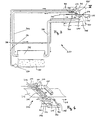
- this web 312 consists of paper and runs along a track in a print shop.
- a spray head 314 sprays an upper web side 316 with one Humidification medium like water, while one versus a lower one Web side 316 'and behind in web direction (arrow 318) the second spray head arranged after the first spray head 314 314 'in a corresponding manner moistens the lower web side 316'.
- To achieve a uniform and efficient humidification web 312 is one for each spray head 314 and 314 ' Assigned electrode arrangement 320 or 320 ', which in each case Spray area of the spray heads 314 an electric field generated and the web 312 in the respective spray area electrically charges, causing the impingement of particles of the dampening medium, here water droplets, on the corresponding one Track side 316 or 316 'is promoted.
- Fig. 3 is the humidification device shown in Fig. 2 shown in more detail, the IV marked area the area shown in Fig. 2 corresponds.
- a humidifying medium 330 becomes a reservoir 332 by means of a pump 334 via a line 336, which one at 338 located branch to the spray heads 314 and 314 'promoted.
- a control unit controls the pump 334 and enables the setting of a desired pressure of the the dampening medium reaching the spray heads, whereby the Degree of dampening of the printing web 312 in a large area can be adjusted.
- the Control unit also, for example, electrically operated valve means in the spray heads to control the amount of sprayed To change the dampening medium.
- humidification device 310 becomes a humidification medium constant pressure to spray heads 314 and 314 ' whereby the structure in the area of pressure generation and Area of the spray heads 314 simplified.
- each spray head 314 and 314 ' each associated with two baffle plates 340 movable relative to each other, located between a spray head 314 or 314 'and the printing web 312 are located and serve in a controlled manner Part of that from the respective spray head 314 or 314 'dampening medium emerging from the printing web 312 withholding.
- the baffle plates 340 serve as panels with variable "passage” and can be driven by means not shown (e.g. Cylinder-piston units) in the direction of the double arrow 342 be moved relative to each other.
- baffle plates 340 are trough-shaped and leave in the example shown, only the part of the respective Spray head outgoing dampening medium on the Track 312, which is between these baffles 340 passes through.
- baffles associated with the lower spray head 314 ' 340 dampening medium retained falls on one below the baffle 340 arranged collection tray 348 and in a corresponding manner via a further return line 350 passed back to the reservoir 332.
- FIG. 4 shows the humidification device according to FIG. 4 in one perspective view, wherein in Fig. 4 three spray heads 314 and 314 ', respectively, to illustrate like using a variety of spray heads Uniformity of humidification can further improve.
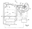
- the humidifier 410 includes an upper spray head 414 and a lower spray head 414 ', each of which, on the one hand, comprises humidifying medium 430 the storage container 432 and on the other hand additionally Compressed air, starting from one compressed air source 460 over two Compressed air valves 462 and two compressed air lines 464, supplied becomes. This is a particularly fine commissioning of the Humidification medium possible. However, the expense is disadvantageous to provide the compressed air.
- the Humidification medium 430 via line 438 initially in buffer 466 or 466 ' is promoted, which in its Height are adjustable.
- These buffers 466 are each provided with an overflow line 468, which is a return of the humidification medium from the respective buffer 466 or 466 'cause back to reservoir 432 as soon as the liquid level in each case predetermined levels N or N ' exceeds.
- the two buffers 466 and 466 ' are via supply lines 470 each with the associated spray heads 414 or 414 'connected and supply this humidification medium with a given by the respective liquid level N or N ' hydrostatic pressure.
- N not necessarily a movement of the relevant buffer is necessary, rather is sufficient with the corresponding Design a change in the corresponding liquid level even by changing the fill level in the buffer stores.
- the hydrostatic is generally Select a higher pressure at the lower spray head 414 ' be d. H. the associated level N 'then becomes higher than that other levels N must be arranged.
- a control unit 474 is provided to control the pump 434 two compressed air valves 462, the two spray heads 414 and two lifting devices 472 for controlled lifting and lowering of the to control two buffers 466.
- These lifting devices can, for example, by a cylinder-piston unit be formed.
- it is also conceivable that instead of these lifting devices from the control unit 474 means for Setting the liquid level in the buffer stores 466 can be controlled, whereby, as described above, the change the hydrostatic pressures is also made possible.
Abstract
Description
Die vorliegende Erfindung betrifft ein Verfahren zur Steuerung oder Regelung einer Periodenlänge wenigstens einer Druckbahn, welche ein sich mit der Periodenlänge periodisch wiederholendes Muster aufweist, sowie eine zur Durchführung eines derartigen Verfahrens geeignete Vorrichtung. Ein derartiges Verfahren und eine entsprechende Vorrichtung ist dem Dokument EP-A-0 463 213 zu entnehmen.The present invention relates to a method for control or regulation of a period length of at least one printing path, which is a periodically repeating with the period length Has patterns, and one for performing such Device suitable for the method. Such a method and a corresponding device can be found in document EP-A-0 463 213.
Der Begriff "Druckbahn" erstreckt sich hierbei auf jegliche zur Verarbeitung mittels Druckmaschinen bzw. Finishing-Maschinen geeignete Bahn beliebigen Materials. Dabei kommen beispielsweise Bahnen aus papierartigem Material und insbesondere Papierbahnen in Betracht.The term "printing web" extends here to any for processing by means of printing machines or finishing machines suitable web of any material. Here come for example Sheets of paper-like material and in particular Paper webs into consideration.
Um ausgehend von einer Druckbahn ein fertiges Druckerzeugnis herzustellen, ist es oftmals notwendig, die Bahn einer Vielzahl von Verfahrensschritten zu unterziehen. Die in jeweiligen Bearbeitungsstationen durchgeführten Bearbeitungsschritte, wie beispielsweise Bedrucken, Perforieren, Gummieren, Lackieren oder Schneiden, bearbeiten die Druckbahn meist abschnittsweise zu einer Bahn mit periodisch sich wiederholendem Muster. Die Periodenlänge der Druckbahn (Passerlänge) ist hierbei durch die Bearbeitungsperiodenlänge der jeweiligen Bearbeitungsstation bestimmt, beispielsweise durch die Umfangslänge des Druckzylinders einer Rotationsdruckmaschine.To produce a finished printed product based on a printing web it is often necessary to manufacture the web of a variety to undergo of procedural steps. The one in each Machining stations performed machining steps, such as for example printing, perforating, gumming, painting or cutting, usually process the print section in sections to a path with a periodically repeating pattern. The Period length of the printing web (register length) is here by the processing period length of the respective processing station determined, for example by the circumferential length of the Printing cylinder of a rotary printing machine.
Eine bereits durch Abschnitte strukturierte Druckbahn muß einer nachfolgenden Bearbeitungsstation in jedem Fall "phasenrichtig" zugeführt werden, d. h. einerseits muß die Frequenz, mit der die Abschnitte der Druckbahn in die Bearbeitungsstation laufen gleich deren Bearbeitungsfrequenz sein, und andererseits wird durch die Bearbeitungsstation für jeden Zeitpunkt der Bearbeitungsperiode die relative Position der Abschnitte der Druckbahn (Passer) vorgegebenen. In Anbetracht dieser Forderungen wurden bisher Bearbeitungsmaschinen meistens mit einer sogenannten Registersteuerung ausgestattet, welche für eine "phasenrichtige" Zufuhr der Druckbahn sorgt, indem die "Phase", d. h. die Lage der Abschnitte auf der Druckbahn relativ zur Bearbeitungsstation in einem bestimmten Zeitpunkt innerhalb der Bearbeitungsperiode, vor der Bearbeitungsstation gemessen wird und in Abhängigkeit vom Meßergebnis die Bearbeitungsfrequenz der Bearbeitungsstation entsprechend etwas verkleinert oder vergrößert wird. Auch ist es bekannt, eine abgezweigte Teilbahn (= Teilsplit) zur phasengerechten Rückführung zur verbliebenen Hauptbahn über einen Kompensator zu führen.A print path already structured by sections must be one subsequent processing station "in phase" in any case are supplied, d. H. on the one hand, the frequency, with which the sections of the printing web into the processing station run equal to their processing frequency, and on the other hand is through the processing station at any time the processing period the relative position of the sections the printing path (register). In view of So far, these requirements have mostly been processing machines equipped with a so-called register control, which ensures "in-phase" feeding of the printing web, by the "phase", i.e. H. the location of the sections on the Print path relative to the processing station in a particular one Time within the processing period, before the processing station is measured and depending on the measurement result the processing frequency of the processing station accordingly something is reduced or enlarged. It is also known a branched-off partial path (= partial split) for the correct phase Return to the remaining main line via a compensator respectively.
Wenn eine Druckbahn nach ihrer Bearbeitung zunächst zu einer Rolle aufgewickelt wird, um später von dieser Rolle abgewickelt und weiter verarbeitet zu werden (Off-Line-Finishing), wie es aus wirtschaftlichen Gründen oftmals erforderlich ist, so kann sich die Periodenlänge der Bahn in nicht vorhersehbarer Weise ändern, beispielsweise abhängig von der Lagerungsdauer, der Lagerungstemperatur oder -feuchtigkeit. Auch kann die Periodenlänge innerhalb ein und derselben Bahnrolle variieren, beispielsweise wenn sich nach einer gewissen Lagerungszeit einer frisch bedruckten Bahnrolle in dieser Bahn ein sich in radialer Richtung änderndes Feuchtigkeitsprofil einstellt.If a printing web first becomes a Roll is wound up to later be unwound from this roll and to be further processed (off-line finishing), as is often necessary for economic reasons, so the period length of the orbit can become unpredictable Change manner, for example depending on the storage period, storage temperature or humidity. Can too the period length vary within the same web roll, for example if after a certain storage period a freshly printed web roll in this web changes the moisture profile in the radial direction.
Es gibt den Wunsch, mehrere bereits bearbeitete Druckbahnen, z. B. am Ende einer Off-Line-Finishing-Anlage, zusammenzuführen, um diese Bahnen gemeinsam weiter zu verarbeiten. Hier ergibt sich jedoch das Problem, daß kontinuierliche Druckbahnen mit unterschiedlichen bzw. variierenden Periodenlängen nicht zusammengeführt und in gegenseitiger Anlage wenigstens über eine gewisse Bahnlaufstrecke passergenau geführt werden können. Auch eine oder eine der Anzahl von Bahnen entsprechende Anzahl von Registersteuerungen kann dieses Problem nicht lösen, da die passergenaue Zusammenführung mehrerer Bahnen zwingend die exakte Entsprechung der Periodenlängen dieser Bahnen erfordert. There is a desire to have multiple print webs already processed, e.g. B. at the end of an off-line finishing system, to further process these webs together. Here results however, the problem is that continuous printing webs with different or varying period lengths merged and in mutual investment at least over a certain web running route can be carried out in register. Also one or one corresponding to the number of lanes Number of register controls cannot solve this problem since it is imperative that several lanes be merged precisely the exact correspondence of the period lengths of these orbits required.
Angesichts der oben erwähnten Nachteile, die sich aus einer nicht kontrollierten Variation der Periodenlänge einer Druckbahn ergeben, ist es Aufgabe der vorliegenden Erfindung, ein Verfahren sowie eine Vorrichtung zur gezielten Beeinflussung der Periodenlänge zu schaffen, insbesondere um die Anpassung der Periodenlänge einer Druckbahn an die Periodenlänge wenigstens einer weiteren Druckbahn zu ermöglichen.Given the disadvantages mentioned above, which result from a uncontrolled variation in the period length of a printing web result, it is an object of the present invention, a Method and a device for targeted influencing the period length to create, especially to adjust the period length of a printing web to the period length at least to enable another printing path.
Erfindungsgemäß wird ein Verfahren zur Steuerung oder Regelung einer Periodenlänge wenigstens einer längs einer Bahnlaufstrecke laufenden und ein in Bahnlaufrichtung sich mit der Periodenlänge periodisch wiederholendes Muster aufweisenden Druckbahn vorgeschlagen, wobei man zur Erzielung einer gewünschten Periodenlänge die Druckbahn am Anfang der Bahnlaufstrecke mehr oder weniger stark befeuchtet.According to the invention, a method for control or regulation a period length of at least one along a track current and one in the web running direction with the Period length showing a periodically repeating pattern Printing path is suggested, taking one to achieve a desired one Period length of the printing web at the beginning of the web running section more or less moisturized.
Der Erfindung liegt die Erkenntnis zugrunde, daß sich die Länge eines Abschnitts auf einer Druckbahn bzw. die Periodenlänge durch Befeuchtung dieser Druckbahn verändern, im allgemeinen vergrößern läßt. Bei Kenntnis des Zusammenhangs zwischen dem Grad der Befeuchtung der Druckbahn und der daraus resultierenden Längenänderung eines Abschnitts ist es somit möglich, eine gewünschte Periodenlänge der Druckbahn einzustellen. Insbesondere ist es möglich, die Periodenlängen verschiedener Druckbahnen, welche zusammengeführt werden sollen, aneinander anzupassen, so daß diese Bahnen passergenau zusammengeführt werden können, was beim Off-Line-Finishing bisher nicht möglich war.The invention is based on the finding that the length of a section on a printing path or the period length change by moistening this print web, in general can enlarge. Knowing the relationship between the Degree of moistening of the printing web and the resulting Changing the length of a section is therefore possible set the desired period length of the printing path. In particular it is possible to change the period lengths of different print paths, which should be merged, to adapt to each other, so that these tracks are merged into register can do what was previously not possible with off-line finishing.
Es ist zweckmäßig, insbesondere wenn der Zusammenhang zwischen Befeuchtung und Abschnittslängenänderung der Druckbahn nicht hinreichend genau bekannt ist oder wenn die tatsächliche Periodenlänge der Druckbahn nicht bekannt ist bzw. variiert, eine Regelung der Periodenlänge vorzusehen, beispielsweise indem man am Ende der Bahnlaufstrecke die momentane Periodenlänge ermittelt und mit einer Soll-Periodenlänge vergleicht, wobei man in Abhängigkeit von der Differenz zwischen momentaner Periodenlänge am Ende der Bahnlaufstrecke und Soll-Periodenlänge die Druckbahn am Anfang der Bahnlaufstrecke mehr oder weniger stark befeuchtet. Damit ist unabhängig von der Beschaffenheit der Druckbahn sowie von sonstigen Nebenbedingungen sichergestellt, daß die Periodenlänge auf eine gewünschte Soll-Periodenlänge gebracht werden kann.It is useful, especially if the connection between Do not moisten and change the length of the printing web is known with sufficient accuracy or if the actual period length the printing web is unknown or varies, to provide regulation of the period length, for example by having the current period length at the end of the track determined and compared with a target period length, depending on the difference between the current Period length at the end of the path and target period length the print web at the beginning of the web run more or less moisturized. It is independent of the Condition of the printing web and other additional conditions ensured that the period length to a desired Target period length can be brought.
Erfindungsgemäß wird vorgeschlagen, daß man bei mehreren anschließend an die jeweilige Bahnlaufstrecke zur gemeinsamen Bearbeitung zusammenzuführenden Druckbahnen die Periodenlänge der Druckbahnen aneinander anpaßt, ggf. aneinander angleicht. Dies ermöglicht die Herstellung eines Druckerzeugnisses aus mehreren Druckbahnen, bei dem eine Entsprechung zwischen den einzelnen Periodenlängen, insbesondere bei gleicher Bahnspannung der unterschiedlichen Bahnen, gefordert ist. Generell müssen die Periodenlängen der verschiedenen Druckbahnen gleich sein bzw. einander entsprechen, derart, daß sie im Verhältnis ganzer Zahlen stehen. Beispielsweise können die Druckbahnen Abschnitte aufweisen, deren Abschnittslängen sich von Druckbahn zu Druckbahn zwar unterscheiden, wobei jedoch die Abschnitte sämtlicher Druckbahnen jeweils aus einem oder mehreren, nebeneinander liegenden Unterabschnitten einheitlicher Länge zusammengesetzt sind. In diesem Fall werden die Periodenlängen der verschiedenen Druckbahnen nicht angeglichen, sondern aneinander angepaßt, derart, daß die Längen der zur Deckung zu bringenden Unterabschnitte exakt aneinander angeglichen werden.According to the invention it is proposed that one subsequently connect to several to the respective railway line to the common Editing the print paths to be merged the period length adapts the printing webs to one another, if necessary, adjusts to one another. This enables the production of a printed product several printing paths, in which a correspondence between the individual period lengths, especially with the same web tension of the different tracks is required. As a general rule the period lengths of the different printing paths must be the same be or correspond to each other in such a way that they are in proportion integers. For example, the printing webs Have sections whose section lengths differ from printing web to differentiate printing web, but the sections all printing webs each from one or more, adjacent subsections more uniform Length are composed. In this case, the period lengths the different printing paths are not adjusted, but adapted to each other, such that the lengths of the to Sub-sections to be covered exactly aligned become.
Wenn mehrere Druckbahnen zusammenzuführen sind, kann man außerdem vorteilhaft vorsehen, daß man am Anfang der Bahnlaufstrecke die momentanen Periodenlängen dieser Druckbahnen ermittelt und abhängig von den ermittelten Periodenlängen die jeweiligen, gewünschten Periodenlängen bzw. Soll-Periodenlängen festlegt. Damit werden die gewünschten Periodenlängen bzw. Soll-Periodenlängen individuell an die ursprünglich vorliegenden Periodenlängen der zusammenzuführenden Druckbahnen angepaßt. In diesem Fall ist es insbesondere möglich, daß man die Druckbahn mit dem vergleichsweise größten Wert der momentanen Periodenlänge am Anfang der Bahnlaufstrecke nicht oder nur sehr wenig befeuchtet. Falls die Periodenlängen der Druckbahnen aneinander anzugleichen sind, so wird dies die Druckbahn mit dem größten Wert der momentanen Periodenlänge am Anfang der Bahnlaufstrecke sein. Sind die Periodenlängen der Druckbahnen jedoch aneinander anzupassen, derart, daß jeweils sich entsprechende Unterabschnitte der verschieden langen Druckbahnabschnitte auf die gleiche Unterabschnittslänge gebracht werden, so wird dies die Druckbahn mit dem größten Wert der momentanen Unterabschnittslänge am Anfang der Bahnlaufstrecke sein.If several print paths are to be merged, you can also It is advantageous to provide that at the beginning of the railway line the current period lengths of these printing webs determined and depending on the determined period lengths the respective desired period lengths or target period lengths specifies. The desired period lengths or Target period lengths individually to the originally available Period lengths of the print paths to be merged adjusted. In this case, it is particularly possible that the Print path with the comparatively largest value of the current one Period length at the beginning of the railway line is not or only very little moisturized. If the period lengths of the printing paths are to be aligned with each other, so this becomes the printing web with the largest value of the current period length at the beginning the track. Are the period lengths of the printing webs but to adapt to each other, such that each corresponding subsections of the printing web sections of different lengths brought to the same subsection length will be the printing web with the greatest value of current subsection length at the beginning of the track his.
Um die relative Position der Abschnitte auf der Druckbahn in Bahnlängsrichtung (Passer) am Ende der Bahnlaufstrecke zu steuern, kann man vorsehen, daß man die Druckbahn durch einen Druckbahnspeicher mit variabler gespeicherter Bahnlänge führt, im Bahnverlauf nach dem Druckbahnspeicher die relative Position der Abschnitte auf der Druckbahn in Bahnlängsrichtung mißt und in Abhängigkeit von dieser Position der Abschnitte die momentan gespeicherte Bahnlänge verändert. Durch diese Maßnahme ist es möglich, die Druckbahn in einfacher Weise derart mit anderen Druckbahnen zusammenzuführen, daß entsprechende Abschnitte bzw. Unterabschnitte zur Deckung gebracht werden.To the relative position of the sections on the printing path in Longitudinal web direction (register) at the end of the web running route control, you can provide that the print path through a Printing web memory with variable stored web length leads, the relative position in the course of the web after the printing web storage of the sections on the printing web in the longitudinal direction of the web measures and depending on this position of the sections the currently saved path length changed. Through this It is possible to measure the printing web in a simple manner merge with other printing webs that corresponding Sections or subsections are brought to cover.
Um eine Druckbahn auf diese Weise passergenau mit wenigstens einer weiteren Druckbahn zusammenzuführen, ist eine Messung der momentanen Periodenlänge an irgendeiner Stelle der Bahnlaufstrecke jedoch nicht unbedingt erforderlich. Man kann nämlich die Bahn unter der Voraussetzung einer zumindest geringfügigen Verschiebbarkeit relativ zu den anderen Bahnen, beispielsweise mittels der herkömlichen Registersteuerung "phasenrichtig" zuführen, wobei dann ein Ansteigen bzw. Absinken der im Druckbahnspeicher gespeicherten Bahnlänge ein Anzeichen für eine zu kurze bzw. zu lange Periodenlänge der Bahn ist. Um dies zu korrigieren, kann man dann, wenn die momentan gespeicherte Bahnlänge einen oberen Vorgabewert (beispielsweise 3/4 der Druckbahnspeicherkapazität) überschreitet oder einen unteren Vorgabewert (beispielsweise 1/4 der Druckbahnspeicherkapazität) unterschreitet, die Druckbahn am Anfang der Bahnlaufstrecke entsprechend mehr oder weniger stark befeuchten.To register a print web in this way with at least Another measurement path is a measurement the current period length at any point on the track but not absolutely necessary. One can namely the train provided at least a minor one Slidability relative to the other tracks, for example by means of the conventional register control Feed "in phase", with an increase or decrease then the web length stored in the print web memory Signs of a period length that is too short or too long Web is. To correct this, you can, if the currently stored path length has an upper default value (for example 3/4 of the web storage capacity) or a lower default value (for example 1/4 of the web storage capacity) falls below the print path at the beginning Moisten more or less strongly according to the web running route
Zum Befeuchten der Druckbahn, d. h. zum Aufbringen eines Befeuchtungsmediums auf die Bahn, sind zahlreiche Möglichkeiten denkbar. Beispielsweise kann ein Befeuchten mittels einer oder mehrerer rotierender Befeuchtungswalzen erfolgen, welche mit ihrer Umfangsfläche in Kontakt mit der Druckbahn stehen und ihrerseits befeuchtet werden, beispielsweise indem sie mit einem Teil ihrer Umfangsfläche in ein flüssiges Befeuchtungsmedium eintauchen oder mit einem Befeuchtungsmedium besprüht werden. Dabei können diese Befeuchtungswalzen die tangential vorbeigleitende Druckbahn streifen und hierbei benetzen, wobei der Benetzungsgrad mittels der Drehgeschwindigkeit der Walzen oder Verändern des Bahnumschlingungswinkels einstellbar ist. Bevorzugt ist jedoch ein direktes Besprühen der Druckbahn, wodurch eine besonders gleichmäßige und in einfacher Weise zu steuernde Auftragung eines Befeuchtungsmediums auf die Druckbahn möglich ist. Die Effizienz und Gleichmäßigkeit der Befeuchtung wird hierbei noch weiter erhöht, wenn man ein elektrisches Feld im Sprühbereich erzeugt. Dieses elektrische Feld kann beispielsweise dazu führen, daß sich die Druckbahn im Sprühbereich elektrisch auflädt und somit das Befeuchtungsmedium anzieht. Unabhängig davon können elektrisch polarisierte Teilchen des Befeuchtungsmediums auch dadurch einer Kraftwirkung ausgesetzt werden, daß man ein inhomogenes elektrisches Feld im Sprühbereich erzeugt.To moisten the print web, i.e. H. for applying a dampening medium on the train, are numerous options conceivable. For example, moistening by means of or several rotating dampening rollers take place, which with their peripheral surface are in contact with the printing web and are in turn moistened, for example by using a Part of its peripheral surface in a liquid humidification medium immerse or sprayed with a dampening medium become. These dampening rollers can be tangential Strip the passing printing web and wet it, whereby the degree of wetting by means of the speed of rotation of the rollers or changing the web wrap angle is adjustable. However, direct spraying of the printing web is preferred, whereby a particularly smooth and easy way to controlling application of a dampening medium to the printing web is possible. The efficiency and uniformity of humidification is increased even further if you have an electrical Field created in the spray area. This electric field can, for example, lead to the fact that the printing web in Spray area electrically charges and thus the humidification medium attracts. Regardless, can be electrically polarized Particles of the moistening medium also one Power are exposed to an inhomogeneous electrical Field created in the spray area.
Die erfindungsgemäße Vorrichtung umfaßt eine Befeuchtungsvorrichtung für die Druckbahn sowie eine an die Befeuchtungsvorrichtung angeschlossene Steuer/Regeleinheit, die die Befeuchtungsvorrichtung zur Erzielung der gewünschten Periodenlänge bzw. der Soll-Periodenlänge ansteuert. The device according to the invention comprises a moistening device for the printing web as well as one to the dampening device connected control unit that controls the humidifier to achieve the desired period length or the target period length.
Die Erfindung wird im folgenden anhand eines Ausführungsbeispiels mit Bezug auf die beigefügten Zeichnungen näher erläutert. In den Zeichnungen stellen dar:
- Fig. 1
- eine schematische Darstellung einer Vorrichtung zur Regelung der Periodenlängen von vier, jeweils längs einer Bahnlaufstrecke laufenden Druckbahnen, wobei die Periodenlängen einander angeglichen werden und die Druckbahnen passergenau zusammengeführt werden,
- Fig. 2
- eine schematische Darstellung einer Befeuchtungsvorrichtung mit zwei in Bahnlaufrichtung aufeinanderfolgenden Sprüheinheiten,
- Fig. 3
- eine schematische Darstellung einer weiteren Befeuchtungsvorrichtung, welche mit einem Blendensystem zur Steuerung des Befeuchtungsgrads ausgestattet ist,
- Fig. 4
- eine detailliertere, perspektivische Darstellung eines Teils der Befeuchtungsvorrichtung gemäß Fig. 3, und
- Fig. 5
- eine Darstellung einer Befeuchtungsvorrichtung zum Befeuchten einer diese Vorrichtung passierenden Druckbahn.
- Fig. 1
- 1 shows a schematic representation of a device for regulating the period lengths of four printing webs, each running along a web running path, the period lengths being matched to one another and the printing webs being brought together in register,
- Fig. 2
- 1 shows a schematic illustration of a moistening device with two spray units which follow one another in the web running direction,
- Fig. 3
- 1 shows a schematic representation of a further humidification device which is equipped with an aperture system for controlling the degree of humidification,
- Fig. 4
- 3 shows a more detailed, perspective illustration of a part of the moistening device according to FIG. 3, and
- Fig. 5
- a representation of a moistening device for moistening a printing web passing through this device.
Fig. 1 veranschaulicht anhand eines Ausführungsbeispiels die besonders bevorzugte Anwendung des erfindungsgemäßen Verfahrens, nämlich das passergenaue Zusammenführen mehrerer Druckbahnen aus Papier.1 uses an exemplary embodiment to illustrate the particularly preferred application of the method according to the invention, namely the registration of multiple print paths made of paper.
Die dargestellte Vorrichtung umfaßt vier im wesentlichen
gleich aufgebaute Bahnlaufstrecken 101-104, längs deren jeweils
eine von einer Druckbahnrolle 110 abgezogene Druckbahn
111-114 läuft. Das passergenaue Zusammenführen dieser vier
Bahnen 111-114 ist deshalb besonders problematisch, weil es
sich um Bahnen von verschiedenen Rollen handelt, d. h. nicht
um gesplittete Teilbahnen ein und derselben Bahn, sondern um
Bahnen, welche im Rahmen eines Off-Line-Finishing zusammen
weiter verarbeitet werden sollen und dementsprechend nicht
exakt aneinander angepaßte bzw. variierende Periodenlängen
(Passerlängen) aufweisen.The device shown comprises four essentially
identically constructed railroad tracks 101-104, along their respective
a printing web drawn from a
Infolge unterschiedlicher Lagerungsbedingungen haben verschiedene Bahnrollen keine einheitliche Passerlänge, auch wenn sie mit derselben Druckmaschine hergestellt wurden. Daher war es bisher im Off-Line-Finishing nicht möglich, mehrere Rollen gleichzeitig zu bearbeiten und dann passergenau zusammenzuführen.Due to different storage conditions have different Web rolls do not have a uniform register length, even if they do were made with the same printing press. So it was Previously not possible in off-line finishing, multiple roles to process at the same time and then merged into register.
Wenn zwei oder mehr bedruckte Bahnrollen des gleichen Druckmaschinentyps am Ende einer Off-Line-Finishing-Anlage zusammengeführt werden sollen, so müssen die Druckbilder der Bahnen exakt gleiche Länge haben, weil diese sich sonst im Laufe der Zeit mehr und mehr zueinander verschieben würden. Dies gilt zumindest, wenn die zusammengeführten Druckbahnen unter gleicher Bahnspannung stehen, was z. B. bei frischen Klebungen der Bahnen notwendig ist.When two or more printed web rolls of the same type of press merged at the end of an off-line finishing system the printed images of the webs have exactly the same length, because otherwise these Time would shift more and more towards each other. this applies at least if the merged printing paths under the same Web tension are what z. B. with fresh bonds of Lanes is necessary.
Die in Fig. 1 dargestellte Vorrichtung dient dazu, die Periodenlängen P1-P4 der vier Druckbahnen 111-114 auf eine einheitliche Periodenlänge P' am Ende der Bahnlaufstrecken 101-104 zu bringen.The device shown in Fig. 1 is used to measure the period lengths P1-P4 of the four printing paths 111-114 on a uniform Period length P 'at the end of the railway lines 101-104 bring to.
Jede der Bahnen 111-114 durchläuft ausgehend von der jeweiligen
Druckbahnrolle 110 nacheinander in Richtung des Pfeils 115
eine erste Meßeinrichtung 128' zur Messung ihrer momentanen
Periodenlänge am Anfang der Bahnlaufstrecke, eine erste Bahnantriebseinrichtung
120 zum Abziehen der Bahn von der jeweiligen
Rolle 110, eine Befeuchtungsvorrichtung 122 zum gesteuerten
Befeuchten der Bahn, einen Kompensator in Form eines
Druckbahnspeichers 124, welcher eine variable Druckbahnlänge
speichert, eine zweite Bahnantriebseinrichtung 126 und eine
zweite Meßeinrichtung 128 zur Messung der am Ende der Bahnlaufstrecke
vorhandenen Periodenlänge P1'-P4' sowie der relativen
Position der Abschnitte auf der jeweiligen Bahn in Bahnlängsrichtung
(Passer). Die Zusammenführung der Bahnen erfolgt
im Bereich der Umlenkrollen 144 auf der rechten Seite der Fig.
1.Each of the lanes 111-114 runs from the respective one
Printing
Zur Durchführung des erfindungsgemäßen Verfahrens ist ferner
eine Regeleinheit 130 vorgesehen, welche Signale von den soeben
genannten Komponenten empfängt bzw. Signale an diese ausgibt.It is also necessary to carry out the method according to the invention
a
Es ist denkbar, daß mittels der Meßeinrichtung 128' am Anfang
der Bahnlaufstrecken 101-104 jeweils die Periodenlänge der
Bahn gemessen wird und diese Bahn dann durch die Befeuchtungsvorrichtung
122 entsprechend mehr oder weniger befeuchtet
wird, um am Ende der Bahnlaufstrecken 101-104 eine für alle
vier Bahnen 111-114 einheitliche Periodenlänge P' zu erhalten.
Denkbar ist ferner, daß man die einzelnen Periodenlängen P1-P4
bereits kennt und somit auf die Meßeinrichtungen 128' am Anfang
der Bahnlaufstrecken 101-104 verzichten kann.It is conceivable that by means of the measuring device 128 'at the beginning
of the web running routes 101-104 each the period length of the
Web is measured and this web then through the
Im dargestellten Ausführungsbeispiel dienen die Meßeinrichtungen
128' am Anfang der Bahnlaufstrecken 101-104 dazu, die Periodenlängen
P1-P4 der Bahnen 111-114 zu messen und daraus die
am Ende der Bahnlaufstrecken 101-104 gewünschte, einheitliche
Periodenlänge P' zu ermitteln. Diese Ermittlung wird durch die
Regeleinheit 130 durchgeführt, welche die dazu notwendigen Signale
der Meßeinrichtungen 128' über jeweilige Leitungen 170'
empfängt. Um die Druckbahnen 111-114 nicht unnötig viel zu befeuchten,
ist vorgesehen, daß die Bahn mit dem größten Wert
der Periodenlänge nur unwesentlich oder gar nicht befeuchtet
wird und als einheitliche, am Ende der Bahnlaufstrecken 101-104
gewünschte Periodenlänge deren Periodenlänge bzw. eine
geringfügig größere Periodenlänge festgelegt wird. Die letztere
Maßnahme gibt einen gewissen Spielraum in der Hinsicht,
daß eine geringfügige Verkleinerung dieser maximalen Periodenlänge
am Anfang der Bahnlaufstrecke unproblematisch ist.In the illustrated embodiment, the measuring devices are used
128 'at the beginning of the railway lines 101-104, the period lengths
P1-P4 of the lanes 111-114 and measure the
At the end of the railway lines 101-104 desired, uniform
Period length P 'to be determined. This determination is made by the
Wenn nun die am Ende der Bahnlaufstrecken 101-104 gewünschte,
einheitliche Periodenlänge P' in geeigneter Weise festgelegt
ist, so könnte die Messung der Periodenlängen P1-P4 am Anfang
der Bahnlaufstrecken 101-104 dazu verwendet werden, die jeweiligen
Befeuchtungsvorrichtungen 122 anzusteuern. Im dargestellten
Beispiel wird jedoch folgende Regelung der am Ende
der Bahnlaufstrecken 101-104 erhaltenen momentanen Periodenlängen
P1'-P4' verwendet: Die gewünschte momentane Periodenlänge
P' wird als Soll-Periodenlänge verwendet. Am Ende jeder
Bahnlaufstrecke 101-104 werden die jeweiligen momentanen Periodenlängen
P1'-P4' gemessen und jeweils mit dieser Soll-Periodenlänge
P' verglichen. Etwaige Abweichungen der Periodenlängen
P1'-P4' von der Soll-Periodenlänge P' werden dann korrigiert,
indem die Regeleinheit 130 die Befeuchtungsvorrichtungen
122 über die Leitungen 138 entsprechend ansteuert.If now the desired at the end of the railway lines 101-104,
uniform period length P 'set in a suitable manner
the period lengths P1-P4 could be measured at the beginning
of the running tracks 101-104 can be used, the
Im Falle einer Druckbahn aus Papier wird man vorsehen, daß bei
Ermittlung einer im Vergleich zur Soll-Periodenlänge zu kleinen
momentanen Periodenlänge P' der durch die Befeuchtungsvorrichtung
122 hervorgerufene Grad an Befeuchtung der Bahn erhöht
wird und umgekehrt.In the case of a paper web, one will provide that at
Determination of a too small compared to the target period length
instantaneous period length P 'of the
Zur passergenauen Zusammenführung der vier Druckbahnen 111-114
am Ende der Bahnlaufstrecken 101-104 ist es notwendig, daß die
Abschnitte der verschiedenen Druckbahnen 111-114 mit einer
einheitlichen Frequenz am Ende der Bahnlaufstrecken 101-104
ankommen. Dementsprechend müssen die Druckbahnen 111-114 mit
derselben Frequenz durch die ersten Bahnantriebseinrichtungen
120 von den Druckbahnrollen 110 abgezogen werden. Diese Bedingung
muß jedoch nur im zeitlichen Mittel erfüllt werden, weil
in jeder Bahnlaufstrecke 101-104 jeweils ein Kompensator in
Form eines Druckbahnspeichers 124 eingefügt ist. Jeder dieser
Druckbahnspeicher 124 speichert eine variable Bahnlänge, die
durch die Regeleinheit 130 über Leitungen 160 gesteuert wird. For precise registration of the four printing paths 111-114
at the end of the railway lines 101-104 it is necessary that the
Sections of the different printing webs 111-114 with one
uniform frequency at the end of the railway lines 101-104
arrive. Accordingly, the printing webs 111-114 must
same frequency by the first
Somit ist es zumindest zeitweilig durch Änderung dieser gespeicherten Bahnlänge möglich, eine Differenz der Bahnlaufgeschwindigkeiten zwischen Eingang und Ausgang des Druckbahnspeichers 124 zu ermöglichen. Die Druckbahnspeicher 124 übernehmen auch die Funktion einer "Registersteuerung", indem sie die relative Position der Abschnitte der jeweiligen Bahn in Bahnlängsrichtung betrachtet an die entsprechende relative Position der Abschnitte der anderen Druckbahnen anpassen, so daß die Abschnitte nicht nur mit einheitlicher Länge die Vorrichtung verlassen, sondern auch deckungsgleich.Thus, it is at least temporarily saved by changing them Web length possible, a difference in web speeds between the entrance and exit of the printing web storage 124 to enable. The print web storage 124 take over also the function of a "register control" by the relative position of the sections of the respective track in The longitudinal direction of the web considered at the corresponding relative position adjust the sections of the other printing webs so that the sections are not just of uniform length the device leave, but also congruent.
Diese Anpassung der relativen Abschnittspositionen wird durch
Ansteuerung der Druckbahnspeicher 124 durch die Regeleinheit
130 durchgeführt. Die Regeleinheit 130 erhält die hierfür notwendigen
Informationen über die tatsächlichen, momentanen relativen
Positionen der Abschnitte auf den verschiedenen Druckbahnen
111-114 von den jeweiligen Meßeinrichtungen 128 an den
Enden der Bahnlaufstrecken 101-104. Diese Meßeinrichtungen 128
übertragen diese Informationen über entsprechende Leitungen
170 an die Regeleinheit 130.This adjustment of the relative section positions is done by
Control of the print web storage 124 by the
Die Druckbahnspeicher 124 der Bahnlaufstrecken 101-103 umfassen
in Bahnlaufrichtung nacheinander jeweils eine stationäre
Speicherumlenkrolle 146 sowie eine bewegliche Speicherumlenkrolle
148, welche relativ zur stationären Speicherumlenkrolle
146 mit einem Verstellantrieb in Richtung des Doppelpfeils 152
bewegt werden kann, wobei diese Bewegung eine entsprechende
Änderung der momentan gespeicherten Bahnlänge zur Folge hat.
Dieser Verstellantrieb kann allgemein durch beliebige, zu diesem
Zweck geeignete Mittel realisiert sein, beispielsweise
durch einen elektrisch betriebenen Spindelantrieb. Im dargestellten
Beispiel ist der Verstellantrieb jedoch durch ein
Zylinder-Kolben-Aggregat 158 symbolisiert, welches die Bewegung
der beweglichen Speicherumlenkrolle 148 mittels einer
Kolbenstange 156 bewirkt. Das Zylinder-Kolben-Aggregat 158
wird dabei über eine Leitung 160 von der Regeleinheit 130 zur
Einstellung der zu speichernden Bahnlänge angesteuert. The print web storage 124 of the web running routes 101-103 comprise
one stationary one at a time in the direction of web
Der Druckbahnspeicher 124 der Bahnlaufstrecke 104 weist im
Unterschied zu den oben beschriebenen Druckbahnspeichern 124
zur Erhöhung der Speicherkapazität bzw. zur Verringerung der
Trägheit zwei bewegliche Speicherumlenkrollen 148 auf, die zur
gemeinsamen Bewegung relativ zu zwei stationären Speicherumlenkrollen
146 miteinander und über die Kolbenstange 156 mit
dem Zylinder-Kolben-Aggregat 158 verbunden sind.The print web storage 124 of the
Die Periodenlängen P1'-P4' am Ausgang der entsprechenden Druckbahnspeicher 124 weisen aufgrund der oben beschriebenen Regelung eine einheitliche Periodenlänge P' auf. Falls Relativverschiebungen der am Ende der Bahnlaufstrecken 101-104 zusammengeführten Bahnen 111-114 möglich sind, so kann eine momentane Phasenangleichung der Bahnen 111-114 mittels der Druckbahnspeicher 124 erfolgen. Damit decken sich die Abschnitte der zusammengeführten Bahnen über eine größere Länge. Sind Relativverschiebungen der zusammengeführten Bahnen überhaupt nicht oder nur in sehr geringem Umfang (z. B. wegen einer nachfolgenden Verklebung der Bahnen) möglich, so scheidet die Phasenangleichung durch die Druckbahnspeicher 124 aus, so daß die Phasenangleichung nur durch die oben beschriebene gezielte Bahnbefeuchtung erfolgen kann. Bei einer Verklebung der Bahnen 111-114 nach deren Zusammenführung ist zu bedenken, daß in der Praxis meist eine geringfügige Relativverschiebungsmöglichkeit der Bahnen 111-114 besteht, so daß die Ansteuerung der Druckbahnspeicher 124 geringfügig zur Phasenanpassung beitragen kann.The period lengths P1'-P4 'at the output of the corresponding Print web storage 124 have due to the above described Regulation on a uniform period length P '. If relative shifts the one at the end of the railway lines 101-104 merged lanes 111-114 are possible, one can current phase alignment of the tracks 111-114 using the Print path storage 124 take place. This coincides with the sections of the merged tracks over a greater length. Are relative displacements of the merged paths at all not or only to a very small extent (e.g. because of subsequent gluing of the sheets) is possible the phase adjustment by the printing path memory 124, so that the phase adjustment only by that described above targeted web moistening can take place. With a bond the lanes 111-114 after their merging must be considered that in practice mostly a slight possibility of relative displacement of tracks 111-114, so that the control the print path memory 124 slightly for phase adjustment can contribute.
Im dargestellten Ausführungsbeispiel durchläuft jede Bahn 111-114
im Anschluß an den entsprechenden Druckbahnspeicher 124
die zweite Bahnantriebseinrichtung 126, welche eine gewisse,
zur sicheren Bahnführung notwendige Bahnspannung aufrecht erhält.
Die erste Bahnantriebseinrichtung 120 läuft in der Regel
mit konstanter Geschwindigkeit sowie schlupffrei. Die zweite
Bahnantriebseinrichtung 126 läuft mit geringfügig größerer
Geschwindigkeit geregelt in Abhängigkeit von der gewünschten
Bahnspannung sowie mit einem geringfügigen Schlupf, um die
erforderliche Bahnspannung ohne erheblichen Regelungsaufwand
aufrecht zu erhalten. Abweichend vom dargestellten Ausführungsbeispiel
ist es natürlich möglich, die Bahnantriebseinrichtung
120 im Bahnverlauf hinter der entsprechenden Befeuchtungsvorrichtung
122 anzuordnen.In the exemplary embodiment shown, each path runs through 111-114
following the corresponding print web storage 124
the second
Die Bahnantriebseinrichtungen 120 und 126 umfassen jeweils
zwei Antriebsrollen 132, zwischen denen die jeweilige Druckbahn
hindurchgeführt ist und welche von einer Antriebseinheit
134 in Form eines Motors angetrieben werden, der von der Regeleinheit
130 jeweils über eine Leitung 136 angesteuert wird.The
In Fig. 1 befinden sich die beweglichen Speicherumlenkrollen
148 in ihrer Bewegungsrichtung 152 betrachtet zwischen zwei
Positionsdetektoren 162 und 164 der Druckbahnspeicher 124.
Diese Detektoren 162, 164 geben Signale über Leitungen 166
bzw. 168 an die Regeleinheit 130 aus, wenn die bewegliche
Speicherumlenkrolle 148 die den Detektoren 162 bzw. 164 entsprechenden
Positionen erreicht. Diese Positionen entsprechen
jeweils momentan gespeicherten Bahnlängen, bei denen der
Druckbahnspeicher 124 relativ gefüllt bzw. relativ entleert
ist. Beispielsweise kann der durch den Positionsdetektor 162
bestimmte Vorgabewert 3/4 der Druckbahnspeicherkapazität betragen,
während der durch den Positionsdetektor 164 bestimmte
Vorgabewert als ein 1/4 der Druckbahnspeicherkapazität gewählt
werden kann.In Fig. 1 are the movable storage pulleys
148 viewed in their direction of
Wenn die momentan gespeicherte Bahnlänge den durch die Position
des ersten Positionsdetektors 162 vorgegebenen Maximalwert
überschreitet, gibt dieser Detektor 162 ein Signal an die
Regeleinheit 130, welche dann die erste Bahnantriebseinrichtung
120 auf eine geringere Bahnlaufgeschwindigkeit ansteuert,
so daß die Geschwindigkeit am Anfang der Bahnlaufstrecke sich
verringert und in der Folge die momentan im Druckbahnspeicher
124 gespeicherte Bahnlänge sich verkleinert. Analog gibt der
Detektor 164 bei Unterschreiten des durch diesen Detektor vorgegebenen
Minimalwert der gespeicherten Bahnlänge ein Signal
an die Regeleinheit 130 aus, worauf diese die die Bahnlaufgeschwindigkeit
bestimmende Antriebseinrichtung, im dargestellten
Fall die Bahnantriebseinrichtung 120, in umgekehrter Weise
ansteuert, um die gespeicherte Bahnlänge allmählich wieder zu
erhöhen.If the currently saved path length corresponds to the position
of the
Alternativ oder zusätzlich könnte die Befeuchtung der Bahnen
111-114 auch in Abhängigkeit von den jeweiligen momentan in
den Druckbahnspeichern 124 gespeicherten Bahnlängen gesteuert
werden. Zu diesem Zweck kann die Regeleinheit 130 bei Überschreiten
des Maximalwerts bzw. Unterschreiten des Minimalwerts
der gespeicherten Bahnlänge die entsprechende Befeuchtungsvorrichtung
122 zur entsprechenden Korrektur der momentanen
Periodenlänge ansteuern.Alternatively or additionally, the webs could be moistened
111-114 also depending on the respective currently in
the web lengths stored in the print web memories 124 are controlled
become. For this purpose, the
Die Meßeinrichtungen 128 bzw. 128' können beispielsweise durch
an sich bekannte Photoscannereinheiten gebildet sein. Derartige
Photoscannereinheiten sind geeignet, Periodenlängen bzw.
Abschnittslängen von Druckbahnen sowie relative Abschnittspositionen
in Druckbahn-Längsrichtung mittels dafür vorgesehenen
Druckmarken auf der Druckbahn oder auch mittels des auf der
Druckbahn befindlichen Druckbilds selbst zu ermitteln. Im
Stand der Technik dienen diese Photoscannereinheiten als Bestandteil
einer Registersteuerung lediglich dazu, die Bearbeitungsfrequenz
einer nachfolgenden Bearbeitungsstation so einzustellen,
daß die Druckbahn "phasenrichtig" zugeführt wird,
so daß der durch diese Bearbeitungsstation durchgeführte Bearbeitungsschritt
an der dafür vorgesehenen Position bzw. dem
dafür vorgesehenen Teilabschnitt der Bahn ausgeführt wird. Im
Rahmen der Erfindung dient die Meßeinrichtung 128 am Ende der
Bahnlaufstrecken 101-104 jedoch nicht nur zur Messung der relativen
Abschnittspositionen, sondern auch zur Kontrolle der
momentanen Periodenlänge am Ende der jeweiligen Bahnlaufstrecke.
Über eine Leitung 170 wird ein dieser gemessenen Periodenlänge
entsprechendes Signal an die Regeleinheit 130
ausgegeben, um Bahnantriebseinheiten und Druckbahnspeicher,
deren Anordnung und Anzahl an den jeweiligen Zweck angepaßt
werden kann, geeignet anzusteuern.The measuring
Die Befeuchtungsvorrichtungen 122 der Bahnlaufstrecken 101 und
102 umfassen in Bahnlaufrichtung nacheinander angeordnete
Sprüheinheiten mit jeweils einem Sprühkopf 140 sowie einer
Hochspannungseinheit 142 auf der vom zugeordneten Sprühkopf
140 abgewandten Seite der entsprechenden Bahn 111 bzw. 112.
Mit dem Sprühkopf 140 wird jeweils ein Befeuchtungsmedium, im
einfachsten Fall Wasser, auf die dem Sprühkopf 140 zugewandte
Bahnseite gesprüht, wobei das Auftreffen der Wassertröpfchen
auf der Bahn durch den Umstand gefördert wird, daß dieselbe im
Sprühbereich durch die zugeordnete Hochspannungseinheit 142
elektrisch aufgeladen wird. Besonders vorteilhafte Befeuchtungsvorrichtungen
dieser Art werden unten anhand der Fig. 3
bis 5 noch detaillierter beschrieben.The dampening
Die Befeuchtungsvorrichtungen 122 der Bahnlaufstrecken 103 und
104 werden jeweils durch Walzenanordnungen gebildet, die jeweils
eine teilweise in ein Befeuchtungsmedium getauchte Befeuchtungswalze
105 umfassen, welche das Befeuchtungsmedium
auf die jeweilige Druckbahn überträgt. Die Steuerung des Grades
der Befeuchtung der jeweiligen Druckbahn 113 bzw. 114 läßt
sich dabei durch Einstellung der Drehgeschwindigkeit dieser
Befeuchtungswalzen 105 und/oder des Umschlingungswinkels variieren,
mit dem die Druckbahn diese Walze 105 umschlingt.The dampening
Es sei noch angemerkt, daß der Einsatz der erfindungsgemäßen Bahnbefeuchtung und der damit verbundenen Abschnittslängenänderung längs einer Bahnlaufstrecke die Möglichkeit schafft, eine Druckbahn einer nachfolgenden Bearbeitungsstation derart zuzuführen, daß kein oder nur sehr geringer "Bearbeitungsschlupf" (bei einer Druckmaschine, beispielsweise Schlupf zwischen der Druckbahn und dem Druckzylinder) erforderlich ist, um die Bearbeitungsfrequenz, d. h. im Falle einer Rotationsdruckmaschine die Rotationsfrequenz des Druckzylinders, an die Frequenz der in die Bearbeitungsstation einlaufenden Abschnitte anzupassen. Dies kann besonders in Fällen vorteilhaft, sein, in denen ein derartiger Schlupf unerwünscht ist.It should also be noted that the use of the invention Web moistening and the associated change in section length creates the opportunity along a track a printing path of a subsequent processing station to ensure that no or very little "machining slip" (in a printing press, e.g. slip between the printing path and the printing cylinder) is required, around the machining frequency, d. H. in the case of a rotary printing press the rotation frequency of the impression cylinder to which Frequency of the sections entering the processing station adapt. This can be particularly advantageous in cases in which such a slip is undesirable.
Fig. 2 zeigt schematisch eine Befeuchtungsvorrichtung 310 zum
Befeuchten einer diese Vorrichtung passierenden Druckbahn 312.
Im dargestellten Fall besteht diese Bahn 312 aus Papier und
läuft längs einer Bahnlaufstrecke in einer Druckerei.2 schematically shows a
Ein Sprühkopf 314 besprüht eine obere Bahnseite 316 mit einem
Befeuchtungsmedium wie Wasser, während ein gegenüber einer unteren
Bahnseite 316' und in Bahnlaufrichtung (Pfeil 318) hinter
dem ersten Sprühkopf 314 angeordneter zweiter Sprühkopf
314' in entsprechender Weise die untere Bahnseite 316' befeuchtet.A
Zur Erzielung einer gleichmäßigen und effizienten Befeuchtung
der Bahn 312 ist jedem Sprühkopf 314 und 314' jeweils eine
Elektrodenanordnung 320 bzw. 320' zugeordnet, welche im jeweiligen
Sprühbereich der Sprühköpfe 314 ein elektrisches Feld
erzeugt und die Bahn 312 im jeweiligen Sprühbereich elektrisch
auflädt, wodurch das Auftreffen von Partikeln des Befeuchtungsmediums,
hier Wassertröpfchen, auf die entsprechende
Bahnseite 316 bzw. 316' gefördert wird.To achieve a uniform and
In Fig. 3 ist die in Fig. 2 dargestellte Befeuchtungsvorrichtung detaillierter dargestellt, wobei der in Fig. 3 mit IV gekennzeichnete Bereich dem in Fig. 2 dargestellten Bereich entspricht.In Fig. 3 is the humidification device shown in Fig. 2 shown in more detail, the IV marked area the area shown in Fig. 2 corresponds.
Ein Befeuchtungsmedium 330 wird aus einem Vorratsbehälter 332
mittels einer Pumpe 334 über eine Leitung 336, welche eine bei
338 befindliche Abzweigung aufweist, zu den Sprühköpfen 314
und 314' gefördert.A humidifying medium 330 becomes a
Eine nicht dargestellte Steuereinheit steuert die Pumpe 334 an
und ermöglicht die Einstellung eines gewünschten Drucks des zu
den Sprühköpfen gelangenden Befeuchtungsmediums, wodurch der
Befeuchtungsgrad der Druckbahn 312 in einem großen Bereich
eingestellt werden kann. Alternativ oder zusätzlich kann die
Steuereinheit auch beispielsweise elektrisch betätigte Ventilmittel
in den Sprühköpfen ansteuern, um die Menge des gesprühten
Befeuchtungsmediums zu verändern. Bei der dargestellten
Befeuchtungsvorrichtung 310 wird jedoch Befeuchtungsmedium
konstanten Drucks zu den Sprühköpfen 314 und 314' geleitet,
wodurch sich der Aufbau im Bereich der Druckerzeugung und im
Bereich der Sprühköpfe 314 vereinfacht. Um dennoch den Befeuchtungsgrad
zu steuern, sind jedem Sprühkopf 314 und 314'
jeweils zwei relativ zueinander bewegbare Prallbleche 340 zugeordnet,
die sich jeweils zwischen einem Sprühkopf 314 bzw.
314' und der Druckbahn 312 befinden und dazu dienen, in gesteuerter
Weise einen Teil des vom jeweiligen Sprühkopf 314
bzw. 314' ausgehenden Befeuchtungsmediums von der Druckbahn
312 zurückzuhalten.A control unit, not shown, controls the
Die Prallbleche 340 dienen als Blenden mit variablem "Durchlaß"
und können durch nicht dargestellte Antriebsmittel (z. B.
Zylinder-Kolben-Aggregate) in Richtung des Doppelpfeils 342
relativ zueinander bewegt werden.The
Die Prallplatten 340 sind wannenförmig ausgebildet und lassen
im dargestellten Beispiel lediglich den Teil des von dem jeweiligen
Sprühkopf ausgehenden Befeuchtungsmediums auf die
Bahn 312 auftreffen, welcher zwischen diesen Prallblechen 340
hindurchtritt.The
Die Wannenboden der in Fig. 3 oberhalb der Bahn 312 angeordneten
Prallbleche 340 münden in Rücklauföffnungen 344 einer
Rücklaufleitung 346, welche das von den Prallblechen 340 zurückgehaltene
Befeuchtungsmedium zum Vorratsbehälter 332 zurückleitet,
wobei ein Abfließen des Befeuchtungsmediums in die
Rücklaufleitung 346 hinein in einfacher Weise durch eine Neigung
der wannenförmigen Prallbleche 340 gefördert werden kann.
Denkbar ist jedoch auch, daß hierfür eine zusätzliche Pumpe
eingesetzt wird. The tub floor of the one arranged above the
Das von den dem unteren Sprühkopf 314' zugeordneten Prallblechen
340 zurückgehaltene Befeuchtungsmedium fällt auf eine unterhalb
der Prallfläche 340 angeordnete Auffangwanne 348 und
wird in entsprechender Weise über eine weitere Rücklaufleitung
350 zurück zum Vorratsbehälter 332 geleitet.That of the baffles associated with the lower spray head 314 '
340 dampening medium retained falls on one below
the
Fig. 4 zeigt die Befeuchtungsvorrichtung gemäß Fig. 4 in einer
perspektivischen Ansicht, wobei in Fig. 4 jeweils drei Sprühköpfe
314 bzw. 314' eingezeichnet sind, um zu veranschaulichen,
wie die Verwendung einer Vielzahl von Sprühköpfen die
Gleichmäßigkeit der Befeuchtung weiter verbessern kann.FIG. 4 shows the humidification device according to FIG. 4 in one
perspective view, wherein in Fig. 4 three
In Fig. 5 ist eine weitere Ausführungsform einer Befeuchtungsvorrichtung
dargestellt, wobei analoge bzw. gleichwirkende
Komponenten der Vorrichtung mit den gleichen Bezugszahlen, jedoch
vermehrt um die Zahl 100, gekennzeichnet sind. Es wird
nun lediglich auf die Unterschiede zur soeben beschriebenen
Vorrichtung eingegangen. Die Befeuchtungsvorrichtung 410 umfaßt
einen oberen Sprühkopf 414 sowie einen unteren Sprühkopf
414', welchen jeweils einerseits Befeuchtungsmedium 430 aus
dem Vorratsbehälter 432 und andererseits zusätzlich jeweils
Druckluft, ausgehend von einer Druckluftquelle 460 über zwei
Druckluftventile 462 und zwei Druckluftleitungen 464, zugeführt
wird. Damit ist eine besonders feine Beauftragung des
Befeuchtungsmediums möglich. Nachteilig ist jedoch der Aufwand
zur Bereitstellung der Druckluft.5 shows a further embodiment of a moistening device
shown, with analog or equivalent
Components of the device with the same reference numbers, however
increased by the number 100. It will
now only on the differences to the one just described
Device received. The
Eine weitere Besonderheit dieser Ausführungsform ist, daß das
Befeuchtungsmedium 430 über die Leitung 438 zunächst in Zwischenspeicher
466 bzw. 466' gefördert wird, welche in ihrer
Höhe verstellbar sind. Diese Zwischenspeicher 466 sind jeweils
mit einer Überlaufleitung 468 versehen, welche einen Rücklauf
des Befeuchtungsmediums aus dem jeweiligen Zwischenspeicher
466 bzw. 466' zurück zum Vorratsbehälter 432 bewirken, sobald
der Flüssigkeitsstand jeweilige vorgegebene Niveaus N bzw. N'
überschreitet. Another peculiarity of this embodiment is that the
Humidification medium 430 via
Die beiden Zwischenspeicher 466 und 466' sind über Zufuhrleitungen
470 jeweils mit den zugeordneten Sprühköpfen 414 bzw.
414' verbunden und liefern diesen Befeuchtungsmedium mit einem
durch die jeweiligen Flüssigkeitspegel N bzw. N' vorgegebenem
hydrostatischem Druck.The two
Es sei bemerkt, daß zur Veränderung der Flüssigkeitspegel N, N' nicht unbedingt eine Bewegung der betreffenden Zwischenspeicher notwendig ist, vielmehr genügt bei entsprechender Ausgestaltung eine Veränderung der entsprechenden Flüssigkeitspegel selbst durch Veränderung der Füllhöhe in den Zwischenspeichern.It should be noted that to change the liquid level N, N 'not necessarily a movement of the relevant buffer is necessary, rather is sufficient with the corresponding Design a change in the corresponding liquid level even by changing the fill level in the buffer stores.
Wenn die Bahn 412 auf ihrer oberen und unteren Seite gleichermaßen
befeuchtet werden soll, so wird im allgemeinen der hydrostatische
Druck am unteren Sprühkopf 414' größer zu wählen
sein, d. h. der zugehörige Pegel N' wird dann höher als der
andere Pegel N anzuordnen sein.If the
Eine Steuereinheit 474 ist vorgesehen, um die Pumpe 434, die
beiden Druckluftventile 462, die beiden Sprühköpfe 414 sowie
zwei Hubvorrichtungen 472 zum gesteuerten Heben und Senken der
beiden Zwischenspeicher 466 anzusteuern. Diese Hubvorrichtungen
können beispielsweise durch ein Zylinder-Kolben-Aggregat
gebildet werden. Allerdings ist auch denkbar, daß anstelle
dieser Hubvorrichtungen von der Steuereinheit 474 Mittel zum
Einstellen des Flüssigkeitspegels in den Zwischenspeichern 466
angesteuert werden, wodurch, wie oben beschrieben, die Veränderung
der hydrostatischen Drücke ebenfalls ermöglicht wird.A
Claims (16)
- Process for the register-true bringing together of a plurality of print webs (111-114), the print webs (111-114) running, in each case, along a web run (101-104), having, in each case, a pattern which is periodically repeated with a cycle length (P1-P4) in the direction of web travel and subsequently being brought together at the respective web runs (101-104) for common processing, characterised in that the cycle lengths (P1-P4) of the print webs (111-114) are mutually adapted, in that, in order to achieve the desired cycle lengths (P1'-P4'), the print webs (111-114) are, in each case, more or less heavily moistened at the start of the web runs (101-104).
- Process according to claim 1, characterised in that the cycle lengths (P1-P4) of the print webs (111-114) are mutually adapted.
- Process according to claim 1 or 2, characterised in that the cycle lengths (P1-P4) of the print webs (111-114) are regulated.
- Process according to claim 3, characterised in that at the end of the respective web runs (101-104) the current cycle lengths (P1'-P4') are ascertained and compared with target cycle lengths and in that as a function of the differences between current cycle lengths (P1'-P4') at the end of the respective web runs and target cycle lengths, the print webs (111-114) are, in each case, more or less heavily moistened at the start of the web runs (101-104).
- Process according to one of the preceding claims, characterised in that at the start of the web runs (101-104) the current cycle lengths (P1-P4) of a plurality of print webs (111-114) are ascertained and, as a function of these ascertained cycle lengths (P1-P4,) the respective, desired cycle lengths (P1'-P4') or target cycle lengths are established.
- Process according to claim 5, characterised in that the print web (111-114) with the comparatively greatest value of the current cycle length (P1-P4) is not moistened at the start of the web run (101-104).
- Process according to one of the preceding claims, characterised in that the print web (111-114) is guided by a print web memory (124) with variable stored web lengths, the relative position of portions of the print web (111-114) is measured in the longitudinal direction of the web in the course of the web according to the web memory (124) and the current stored web length is changed as a function of this position of the portions.
- Process according to claim 7, characterised in that if the current stored web length exceeds an upper predetermined value or goes below a predetermined lower value, the print web (111-114) is accordingly more or less heavily moistened at the beginning of the web run (101-104).
- Process according to one of the preceding claims, characterised in that the print web (111-114) is moistened by spraying.
- Process according to claim 9, characterised in that an electric field is produced in the spraying region.
- Device for carrying out the process according to one of the preceding claims, including a plurality of moistening devices (122) for the print webs (111-114), an open/closed loop control unit (130) fixed to the moistening devices (122) which unit (130) controls the moistening devices (122) for obtaining the desired cycle lengths (P1'-P4') or the target cycle lengths and also means (144) for bringing together the print webs at the end of the web runs (101-104).
- Device according to claim 11, characterised in that, at the end of the web runs (101-104) there is provided, in each case, a measuring device (128) which emits a signal, giving the current cycle length (P1'-P4'), to the open/closed loop control unit (130).
- Device according to claim 11 or 12, characterised in that at the start of the web runs (101-104) there is provided, in each case, a measuring device (128') which emits a signal, giving the current cycle lengths (P1-P4) to the open/closed loop control unit (130).
- Device according to one of claims 11 to 13, characterised by at least one print web memory (124) with variable stored web length, as well as by a respective subsequent position measuring unit (128) for measuring the relative position of the portions on the print web (111-114).
- Device according to one of claims 11 to 14, characterised in that the moistening device (122) comprises a spray unit (140).
- Device according to claim 15, characterised in that the moistening device (122) comprises a high voltage source (142) for producing an electric field in the spraying region.
Applications Claiming Priority (3)
| Application Number | Priority Date | Filing Date | Title |
|---|---|---|---|
| DE19650803 | 1996-12-06 | ||
| DE19650803A DE19650803A1 (en) | 1996-12-06 | 1996-12-06 | Length adjustment of section lengths of printing webs |
| PCT/EP1997/006814 WO1998024720A2 (en) | 1996-12-06 | 1997-12-05 | Adaptation of section lengths of a printing line |
Publications (2)
| Publication Number | Publication Date |
|---|---|
| EP0942890A2 EP0942890A2 (en) | 1999-09-22 |
| EP0942890B1 true EP0942890B1 (en) | 2000-06-14 |
Family
ID=7813925
Family Applications (1)
| Application Number | Title | Priority Date | Filing Date |
|---|---|---|---|
| EP97952887A Expired - Lifetime EP0942890B1 (en) | 1996-12-06 | 1997-12-05 | Adaptation of section lengths of a printing line |
Country Status (3)
| Country | Link |
|---|---|
| EP (1) | EP0942890B1 (en) |
| DE (2) | DE19650803A1 (en) |
| WO (1) | WO1998024720A2 (en) |
Families Citing this family (2)
| Publication number | Priority date | Publication date | Assignee | Title |
|---|---|---|---|---|
| DE10326080A1 (en) * | 2003-06-10 | 2005-01-27 | OCé PRINTING SYSTEMS GMBH | Printing line with web storage unit and post-processing system |
| DE10345593A1 (en) * | 2003-09-29 | 2005-07-07 | Koenig & Bauer Ag | Method for determining production-relevant material properties of the substrates and / or elevators |
Family Cites Families (5)
| Publication number | Priority date | Publication date | Assignee | Title |
|---|---|---|---|---|
| DE328786C (en) * | 1920-11-04 | Otto Abt | Device for moistening paper | |
| US3432672A (en) * | 1965-03-04 | 1969-03-11 | Mach O Matic Inc | Photoelectric web registration control including two photocells which generate opposite polarity signals that terminate simultaneously |
| US3556509A (en) * | 1968-08-21 | 1971-01-19 | Harris Intertype Corp | Printed web ribbon registration control system |
| US4795513A (en) * | 1983-02-01 | 1989-01-03 | Adolph Coors Company | Method and apparatus for producing a laminated composite material having perforated inner layer |
| EP0463213A1 (en) * | 1990-06-27 | 1992-01-02 | Jean Hiedemann GmbH & Co.KG | Process for superficially treating a moving paperweb and apparatus for making the same |
-
1996
- 1996-12-06 DE DE19650803A patent/DE19650803A1/en not_active Ceased
-
1997
- 1997-12-05 WO PCT/EP1997/006814 patent/WO1998024720A2/en active IP Right Grant
- 1997-12-05 EP EP97952887A patent/EP0942890B1/en not_active Expired - Lifetime
- 1997-12-05 DE DE59701899T patent/DE59701899D1/en not_active Expired - Fee Related
Also Published As
| Publication number | Publication date |
|---|---|
| WO1998024720A2 (en) | 1998-06-11 |
| WO1998024720A3 (en) | 1998-07-23 |
| DE59701899D1 (en) | 2000-07-20 |
| EP0942890A2 (en) | 1999-09-22 |
| DE19650803A1 (en) | 1998-06-10 |
Similar Documents
| Publication | Publication Date | Title |
|---|---|---|
| DE2951246C2 (en) | ||
| DE3503448C2 (en) | Method and device for moistening an endless web | |
| DE10035787C2 (en) | Process for regulating a web tension | |
| EP0424874B1 (en) | Method and means for reducing discards in rotary printing machines | |
| EP0912435A1 (en) | Method and reeling machine for continuous reeling of a strip of material | |
| EP0950519A1 (en) | Method for self-adjusting the printing and the cutting register in rotary printing machines with several webs | |
| DE3543846A1 (en) | METHOD AND DEVICE FOR POSITIONING A MATERIAL RAIL TO BE PRE-TRANSPORTED | |
| DE19918399A1 (en) | Indexing drive process for cylinder or indexing roll of rotary printing press | |
| DE4402874A1 (en) | System for creating a perfect winding structure | |
| EP0959032B1 (en) | Method and winding machine for winding a material web | |
| DE3135696C2 (en) | Method and apparatus for printing variable formats | |
| EP1303404A1 (en) | Method for regulation of a web tension in a rotary print machine | |
| DE3322996C2 (en) | ||
| EP0942890B1 (en) | Adaptation of section lengths of a printing line | |
| DE3515626C2 (en) | ||
| DE3590386T (en) | Method for controlling the tension of webs in a rotary press and a device for its implementation | |
| EP0755356B1 (en) | Device and process for combining and processing several paper webs | |
| EP0957057B1 (en) | Longitudinal folding device for the folding apparatus of rotary printing machines | |
| EP1826002B1 (en) | Printing press with web tension control | |
| DE19827712A1 (en) | Device for the direct or indirect application of a liquid or pasty application medium to a running material web | |
| EP1519887B1 (en) | Method for determining the course of a drop in tension of a strip and method for adjusting the tension | |
| DE10352621B4 (en) | Method for the lateral alignment of a web | |
| EP1414726A1 (en) | Method and winding machine for the continuous winding of a web of material | |
| DE102004018401A1 (en) | Method for presetting of printing press entails using drive which is in signal communication with presetting system for movement of turning bar at right angles to inlet direction of paper web | |
| DE4345603B4 (en) | Rotary printing machine and web width adjustment method for a printing system |
Legal Events
| Date | Code | Title | Description |
|---|---|---|---|
| PUAI | Public reference made under article 153(3) epc to a published international application that has entered the european phase |
Free format text: ORIGINAL CODE: 0009012 |
|
| 17P | Request for examination filed |
Effective date: 19990520 |
|
| AK | Designated contracting states |
Kind code of ref document: A2 Designated state(s): DE |
|
| GRAG | Despatch of communication of intention to grant |
Free format text: ORIGINAL CODE: EPIDOS AGRA |
|
| GRAG | Despatch of communication of intention to grant |
Free format text: ORIGINAL CODE: EPIDOS AGRA |
|
| GRAH | Despatch of communication of intention to grant a patent |
Free format text: ORIGINAL CODE: EPIDOS IGRA |
|
| 17Q | First examination report despatched |
Effective date: 19991116 |
|
| GRAH | Despatch of communication of intention to grant a patent |
Free format text: ORIGINAL CODE: EPIDOS IGRA |
|
| GRAA | (expected) grant |
Free format text: ORIGINAL CODE: 0009210 |
|
| AK | Designated contracting states |
Kind code of ref document: B1 Designated state(s): DE |
|
| REF | Corresponds to: |
Ref document number: 59701899 Country of ref document: DE Date of ref document: 20000720 |
|
| EN | Fr: translation not filed | ||
| PLBE | No opposition filed within time limit |
Free format text: ORIGINAL CODE: 0009261 |
|
| STAA | Information on the status of an ep patent application or granted ep patent |
Free format text: STATUS: NO OPPOSITION FILED WITHIN TIME LIMIT |
|
| 26N | No opposition filed | ||
| PG25 | Lapsed in a contracting state [announced via postgrant information from national office to epo] |
Ref country code: DE Free format text: LAPSE BECAUSE OF NON-PAYMENT OF DUE FEES Effective date: 20060701 |
|
| PGFP | Annual fee paid to national office [announced via postgrant information from national office to epo] |
Ref country code: DE Payment date: 20060828 Year of fee payment: 9 |