EP0942701B1 - Verfahren, vorrichtung und artikel in zusammenhang mit einem klettverschluszsystem - Google Patents
Verfahren, vorrichtung und artikel in zusammenhang mit einem klettverschluszsystem Download PDFInfo
- Publication number
- EP0942701B1 EP0942701B1 EP97944249A EP97944249A EP0942701B1 EP 0942701 B1 EP0942701 B1 EP 0942701B1 EP 97944249 A EP97944249 A EP 97944249A EP 97944249 A EP97944249 A EP 97944249A EP 0942701 B1 EP0942701 B1 EP 0942701B1
- Authority
- EP
- European Patent Office
- Prior art keywords
- article
- fastening member
- hook members
- end portion
- fastening
- Prior art date
- Legal status (The legal status is an assumption and is not a legal conclusion. Google has not performed a legal analysis and makes no representation as to the accuracy of the status listed.)
- Expired - Lifetime
Links
- 238000000034 method Methods 0.000 title claims abstract description 47
- 238000003860 storage Methods 0.000 claims abstract description 32
- 238000006073 displacement reaction Methods 0.000 claims abstract description 27
- 230000014759 maintenance of location Effects 0.000 claims description 10
- 230000000694 effects Effects 0.000 claims description 7
- 238000011144 upstream manufacturing Methods 0.000 claims description 7
- 230000002745 absorbent Effects 0.000 claims description 6
- 239000002250 absorbent Substances 0.000 claims description 6
- 239000007788 liquid Substances 0.000 claims description 6
- 239000012858 resilient material Substances 0.000 claims description 3
- 206010021639 Incontinence Diseases 0.000 claims description 2
- 239000000463 material Substances 0.000 description 24
- 238000004519 manufacturing process Methods 0.000 description 21
- 239000000470 constituent Substances 0.000 description 4
- 239000000853 adhesive Substances 0.000 description 3
- 230000001070 adhesive effect Effects 0.000 description 3
- 239000002648 laminated material Substances 0.000 description 3
- 239000004820 Pressure-sensitive adhesive Substances 0.000 description 2
- 230000001419 dependent effect Effects 0.000 description 2
- -1 polyethylene Polymers 0.000 description 2
- 239000004677 Nylon Substances 0.000 description 1
- 239000004698 Polyethylene Substances 0.000 description 1
- 239000004743 Polypropylene Substances 0.000 description 1
- 210000001015 abdomen Anatomy 0.000 description 1
- 238000005452 bending Methods 0.000 description 1
- 238000011109 contamination Methods 0.000 description 1
- 238000010586 diagram Methods 0.000 description 1
- FPAFDBFIGPHWGO-UHFFFAOYSA-N dioxosilane;oxomagnesium;hydrate Chemical compound O.[Mg]=O.[Mg]=O.[Mg]=O.O=[Si]=O.O=[Si]=O.O=[Si]=O.O=[Si]=O FPAFDBFIGPHWGO-UHFFFAOYSA-N 0.000 description 1
- 238000009826 distribution Methods 0.000 description 1
- 238000003475 lamination Methods 0.000 description 1
- 238000012423 maintenance Methods 0.000 description 1
- 239000004745 nonwoven fabric Substances 0.000 description 1
- 229920001778 nylon Polymers 0.000 description 1
- 238000004806 packaging method and process Methods 0.000 description 1
- 229920000573 polyethylene Polymers 0.000 description 1
- 229920001155 polypropylene Polymers 0.000 description 1
- 229920002994 synthetic fiber Polymers 0.000 description 1
- 239000002699 waste material Substances 0.000 description 1
Images


Classifications
-
- A—HUMAN NECESSITIES
- A61—MEDICAL OR VETERINARY SCIENCE; HYGIENE
- A61F—FILTERS IMPLANTABLE INTO BLOOD VESSELS; PROSTHESES; DEVICES PROVIDING PATENCY TO, OR PREVENTING COLLAPSING OF, TUBULAR STRUCTURES OF THE BODY, e.g. STENTS; ORTHOPAEDIC, NURSING OR CONTRACEPTIVE DEVICES; FOMENTATION; TREATMENT OR PROTECTION OF EYES OR EARS; BANDAGES, DRESSINGS OR ABSORBENT PADS; FIRST-AID KITS
- A61F13/00—Bandages or dressings; Absorbent pads
- A61F13/15—Absorbent pads, e.g. sanitary towels, swabs or tampons for external or internal application to the body; Supporting or fastening means therefor; Tampon applicators
- A61F13/56—Supporting or fastening means
- A61F13/62—Mechanical fastening means ; Fabric strip fastener elements, e.g. hook and loop
- A61F13/622—Fabric strip fastener elements, e.g. hook and loop
-
- Y—GENERAL TAGGING OF NEW TECHNOLOGICAL DEVELOPMENTS; GENERAL TAGGING OF CROSS-SECTIONAL TECHNOLOGIES SPANNING OVER SEVERAL SECTIONS OF THE IPC; TECHNICAL SUBJECTS COVERED BY FORMER USPC CROSS-REFERENCE ART COLLECTIONS [XRACs] AND DIGESTS
- Y10—TECHNICAL SUBJECTS COVERED BY FORMER USPC
- Y10T—TECHNICAL SUBJECTS COVERED BY FORMER US CLASSIFICATION
- Y10T24/00—Buckles, buttons, clasps, etc.
- Y10T24/27—Buckles, buttons, clasps, etc. including readily dissociable fastener having numerous, protruding, unitary filaments randomly interlocking with, and simultaneously moving towards, mating structure [e.g., hook-loop type fastener]
- Y10T24/2775—Buckles, buttons, clasps, etc. including readily dissociable fastener having numerous, protruding, unitary filaments randomly interlocking with, and simultaneously moving towards, mating structure [e.g., hook-loop type fastener] having opposed structure formed from distinct filaments of diverse shape to those mating therewith
Definitions
- the present invention relates to a method of maintaining a fastening member of a hook and loop fastener system in a storage position on an article, such as a disposable diaper, according to the preamble of claim 1.
- the invention further relates to apparatus according to the preamble of claim 12 for carrying out the method.
- the invention also relates to a diaper according to the preamble of claim 18.
- the region of hook material is located at a distal end portion of the tab and this distal end portion of the tab extends beyond the edge of the diaper to allow the first waist portion of the diaper to be placed around a wearer and secured to the second waist portion to thereby maintain the diaper in place on the wearer.
- a disposable diaper generally comprises a liquid impermeable backsheet, a liquid permeable topsheet, and an absorbent core sandwiched between the topsheet and backsheet.
- disposable diapers may also have elasticated leg cuffs and elasticated waist portions.
- the production process for disposable diapers is highly automated, with constituent materials being supplied to the production line and finished products leaving the production line already packaged for delivery to the consumer. As with all production line processes, faulty batches and stoppages must be avoided.
- Hook and loop fastener systems are applied to partially completed diapers as the diapers proceed along the production line.
- the tabs In order to prevent the fastening tabs of the hook and loop fastener system from fouling machinery as the diapers proceed along the production line, it is important that the tabs be maintained in a storage position in which the distal end portion of the tab is folded over the first end portion to thereby preferably contact the topsheet of the diaper.
- This storage position should be maintained throughout the passage of the diaper along the production line so that the diaper is folded and packaged with the tabs in the storage position. In this manner, when the consumer opens the package, he/she is presented with neatly folded diapers with no visibly protruding tabs.
- a further conceivable solution to this problem could be to provide the topsheet of the diaper with a patch of loop material adjacent the first end portion of the tab such that the distal end portion of the tab carrying the hooks could engage the patch of loop material in the storage position.
- Such a solution would however imply higher costs due to the need for additional loop material.
- the claimed method ensures improved engagement between the surface of the article and the hook members, existing components of the diaper can be utilized for this purpose without the need for additional means such as adhesive or extra loop material.
- the claimed method may be practised on any article which is provided with a hook and loop fastening system. More particularly, the method is eminently suitable for use with disposable articles such as winged sanitary napkins having hook and loop fasteners on the wings, adult incontinence garments and openable-and-reclosable pant diapers.
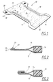
- a diaper is shown generally designated by reference numeral 10.
- the diaper 10 generally comprises a liquid impermeable backsheet 12, a liquid permeable topsheet 14 and an absorbent core 16 therebetween.
- the diaper may also incorporate leg elastic 18 disposed along side margins of the diaper.
- the materials of the constituents of the diaper may be any which are commonly used in this field.
- the backsheet 12 may be a polyethylene film, whilst the topsheet may be manufactured from a wide range of materials, such as natural fibres, synthetic fibres or a combination thereof.
- the material of the topsheet displays fibres which may be engaged by hooks of a hook and loop fastener system.
- a material which is well suited for this purpose is spunbond polypropylene nonwoven fabric, though the actual choice of material will be dependent on the type and configuration of the hook members 20 employed in the hook and loop fastener system.
- a first embodiment of a typical hook and loop fastener system which may be used in the method according to the present invention includes a pair of polymeric fastening members, generally denoted by reference numeral 20, having a first surface or portion 22 attached to a first waist portion 24 of the diaper 10.
- each member 20 has a second surface or portion 26 from which a plurality of hook members 30 project.
- the hook members 30 are adapted to engage with a loop fastener portion 32 positioned on the outer surface of the backsheet 12 in a second waist portion 34 of the diaper.
- the second waist portion 34 of the diaper rests against the abdomen of the wearer, whilst the first waist portion 24 extends over the wearer's back.
- the outer surface of the backsheet be such that it permits the hook members 30 to engage therewith with sufficient retention force, then there is no need to provide the diaper with additional loop fastener portions 32.
- the hook members 30 can be of any suitable material and have any size, shape and distribution density which will allow secure fastening of the fastening tabs to the loop fastener portions 32.
- the hook members can be made of nylon material in hook- or mushroom-shaped form.
- a suitable hook fastener is that sold by 3MTM under the identification code CS200.
- the first portion 22 of the fastening member 20 is permanently attached to the topsheet 14 of the diaper, for example by a suitable adhesive or weld.
- Fig. 3 the fastening member 20 is shown in a storage position, i.e. that position which is desired to be adopted when the diaper 10 passes along the production line and which the fastening member retains when the diaper is packaged.
- a region of the topsheet 14 containing the fastener member 20 is folded over on itself so that the hook members 30 projecting from the second portion 26 of the fastening member contact the outer surface of the topsheet 14.
- the hook members of the fastening member once the hook members of the fastening member have come into contact with the outer surface of the topsheet 14, the hook members of the second portion and the surface of the topsheet are caused to effect a relative displacement in a direction substantially parallel to the surface of the topsheet. It has surprisingly been found that by subjecting these parts to a relative displacement, a significantly increased retention force between the hook members 30 and the outer surface of the topsheet 14 is obtained compared to the retention force obtained when no relative displacement takes place.
- the expression "retention force” includes peel resistance and the shear stress resistance.
- a desirable value of the retention force is one which is capable of maintaining the fastening member 20 in its storage position during passage of the article along the production line and during packaging of the article, though which is not necessarily as high as the retention force between the hook and loop components of a conventional hook and loop fastener.
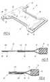
- the hook and loop fastener system of the second embodiment which may be used in the method according to the present invention includes a pair of fastening members, generally denoted by reference numeral 20, in the form of flexible elongate rectangular polymeric fastening tabs made for example from a nonwoven material.
- Each tab has a first portion in the form of a first end portion 122 attached to a first waist portion 24 of the diaper 10.
- each tab 20 has a second portion in the form of a distal end portion 126 which, when the diaper is in a ready position, i.e. a position immediately prior to being attached to a wearer, extends beyond the edge of the diaper.
- the distal end portion 126 of the tab carries a backing 28 from which a plurality of hook members 30 project.
- the hook members 30 are adapted to engage with a loop fastener portion 32 positioned on the outer surface of the backsheet 12 in a second waist portion 34 of the diaper.
- the outer surface of the backsheet be such that it permits the hook members 30 to engage therewith with sufficient retention force, then there is no need to provide the diaper with additional loop fastener portions 32.
- the first end portion 122 of the tab 20 may be branched into a pair of flaps 36, with one flap being adhered to the outer surface of the backsheet 12 and the other flap being adhered to the outer surface of the topsheet 14.
- the first end portion of the tab may be unitary and extend between the topsheet and the backsheet.
- the fastening tab 20 is shown in a storage position, i.e. that position which is desired to be adopted when the diaper 10 passes along the production line and which the fastening tab retains when the diaper is packaged.
- the distal end portion 126 of the tab is folded over the first end portion 122 so that the hook members 30 projecting from the backing 28 contact the outer surface of the topsheet 14.
- the distal end portion 126 and the surface of the topsheet are caused to effect a relative displacement in a direction substantially parallel to the surface of the topsheet.
- the invention may be practised on an openable-and-reclosable pant diaper.
- Such articles generally have a shape corresponding to that of the diaper illustrated in Figs. 1 and 4, though with the exception that the loop fastener portion 32 forms a part of the topsheet in the second waist portion of the diaper.
- the loop fastener portion may be in the form of patches attached to corner regions of the second waist portion or the topsheet itself may serve as such loop fastener portions.
- the storage position for such a pant diaper is adopted when the fastener members on the first waist portion engage the loop fastener portion or portions in the second waist portion. This storage position then corresponds to the position of use of the pant diaper until the pant diaper is unfastened by separating the first waist portion from the second waist portion.
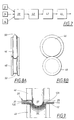
- Fig. 7 schematically illustrates a production line for the production of diapers.
- Boxes 12, 14 and 16 represent the backsheet, topsheet and absorbent core, respectively, with these constituents being fed to a first station represented by box 38 at which the topsheet and backsheet are adhered together with the absorbent core located therebetween.
- the partially finished article proceeds to a second station 40 at which the fastening members are applied.
- the fastening members With the fastening members in their storage position as shown in Figs. 3 and 6, the partially finished article proceeds immediately to a third station 42 at which relative displacement of the second portions of the fastening members and the topsheet of the partially finished diaper is performed.
- the diaper passes through a fourth station 44 at which subsequent finishing operations are performed. From the fourth station 44 a completed and packaged diaper emerges.
- steps 40 and 42 will take place before the article passes to the station 38 at which lamination takes place.
- the third station 42 (Fig. 7) may be provided with a pair of interengaging rollers, one male roller 46 and one female roller 48, for each side of the article to which fastening tabs 20 are affixed.
- the production line will be equipped with two pairs of rollers.
- the male roller 46 has a circumferentially extending protrusion 50 which extends with clearance into a circumferential groove 52 on the female roller 48.
- the clearance between the protrusion 50 and the groove 52 is sufficient to allow the distal end portion 126 of the tab 20 and the laminated topsheet 14 and backsheet 12 of the diaper shown in Fig. 4 to pass therethrough.
- Relative displacement of the distal end portion 126 of the fastening tab 20 and the outer surface of the topsheet 14 is attained due to the hook members 30 being forced to alter their position relative the loop material of the topsheet as the distal end portion 126 of the fastening tab 20 passes through the pair of rollers.
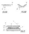
- the occurrence of relative displacement will be clearly apparent from a comparison between Figs. 10A and 10B.
- the second portion 26 of a fastening member is shown in a condition before it is subjected to the method according to the invention in which relative displacement is created.
- the second portion 26 is generally planar and remote tips of a pair of adjacent hook members 30 provided on the second portion are separated by a certain distance y.
- the distance between the tips of the same adjacent hook members 30 increases to a value z.
- Fig. 11 shows a fastening member 20 in its storage position in which the hook members 30 engage fibres and/or loops of a region of the outer surface of the topsheet 14. Due to the fact that the second portion 26 of the fastening member 20 has previously been subjected to bending to create a radius r in the third station 42, once the second portion leaves the third station and the diaper becomes substantially flat, the hook members 30 of the fastening member will exert compressive forces denoted by the letter F on the region of the surface of the topsheet 14 in directions substantially parallel to the surface. These compressive forces aid in increasing the retention force of the fastening member in the storage position.
- the actual size and shape of the interengaging rollers is seemingly not critical. As such, various possible shapes of the interengaging surfaces 50 and 52 are shown by way of example only in Figs. 12A to 12J. It will be noted that in several of the shown embodiment, rubber 54 or similar resilient material may be placed in the groove 52 or along the protrusion 50.
- the male and female rollers may have a diameter of between 20 and 200 mm, advantageously about 100 mm.
- the protrusion 50 on the male roller 46 may advantageously have a radial extension of about 6 mm.
- a section of one embodiment of the diaper production line at the third station 42 is schematically illustrated in Figs. 13 to 16 and comprises a pair of interengaging rollers 46, 48 positioned in a mid portion of a guide groove 56 in a table 58 of the production line.
- the guide groove 56 commences at the upstream side of the pair of rollers 46, 48 and becomes gradually wider and deeper until it reaches the vicinity of the pair of rollers, at which point the table 58 is provided with a through opening 60 within which the pair of rollers interengage.
- the shape of the guide groove 56 is a mirror image of the upstream shape.
- the guide groove 56 serves to guide the second portion of the fastening tab and the portion of the laminate of material in contact with the hook members in a properly aligned manner towards and through the pair of rollers 46, 48.
- the gradual tapering of the downstream portion of the guide groove 56 serves to ensure that the fastening member remains in its storage position once it has passed through the pair of rollers 46, 48.
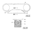
- FIG. 17 and 18 A further embodiment of apparatus suitable for effecting the relative displacement of the second portion of the fastening member and the material which it contacts is illustrated in Figs. 17 and 18 and generally comprises a continuous belt 60 which passes through an upwardly open channel 62 in a folding block 64 mounted on the production line table.
- the belt 60 serves the same function as the male roller 46 in the previously described embodiment, whilst the channel 62 mimics the function of the female roller 48.
- the folding block 64 has a sloping upstream surface 66 along which the second portion of the fastening member and associated portion of the laminate material run before being drawn into the channel 62 by the belt 60.
- the second portion of the fastening member and the laminate material are caused to effect relative displacement to thereby cause the hook members of the fastening tab to enter and engage the surface material of the topsheet.
- An outline of the fastening member and laminate material within the channel 62 is denoted by reference numeral 68 in Fig. 18.
- the folding block 64 is provided with a sloping downstream surface 70 to ensure a smooth exit of the fastening member and material from the channel 62.
- the above-described embodiment is particularly suitable for practising the method according to the invention on fastening members which are relatively wide. This is because the second portion of the fastening member is caused to adopt a configuration within the folding block 64 in which it covers almost the entire periphery of the belt 60. This can be compared to the male rollers illustrated in Fig. 12 in which the second portion of the fastening member covers only a semi-circle.
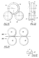
- FIGs. 19 to 22 Alternative apparatus for achieving satisfactory relative displacement of the second portion of a relatively wide fastening member and the surface of the article using rollers is illustrated in Figs. 19 to 22.
- a pair of male rollers 46 are arranged adjacent each other on a common axis 72.
- a first one of these rollers cooperates with a first female roller 48 upstream of the male rollers, whilst the second of the pair of male rollers cooperates with a second female roller 48 downstream of the male rollers.
- this arrangement ensures that relative displacement between the second portion of a fastening member and the surface of the article which it contacts can be achieved even if the width of the second portion exceeds that of the groove 52 of one of the female rollers 48.
- two pairs of cooperating male and female rollers 46, 48 are employed, with one pair being placed upstream relative the other.
- the pairs of rollers are axially offset relative each other so that a width w is created within which relative displacement of the fastening member and the surface of the article is achievable, this width w being greater than the width of the groove 52 of each female roller 48.
- the pair of rollers 46, 48 need not necessarily be arranged along the longitudinal axis of the diaper. It is further conceivable that two female rollers cooperate with one male roller.
- the shape of the protrusion 50 need not match that of the groove 52.
- the protrusion 50 may be rounded whilst the groove 52 has a rectangular cross section.
- the male roller or rollers may be positioned under the female roller or rollers.
Landscapes
- Health & Medical Sciences (AREA)
- Engineering & Computer Science (AREA)
- Animal Behavior & Ethology (AREA)
- Veterinary Medicine (AREA)
- Biomedical Technology (AREA)
- Heart & Thoracic Surgery (AREA)
- Vascular Medicine (AREA)
- Life Sciences & Earth Sciences (AREA)
- Mechanical Engineering (AREA)
- General Health & Medical Sciences (AREA)
- Public Health (AREA)
- Epidemiology (AREA)
- Absorbent Articles And Supports Therefor (AREA)
- Container Filling Or Packaging Operations (AREA)
- Supports Or Holders For Household Use (AREA)
- Auxiliary Devices For And Details Of Packaging Control (AREA)
- Slide Fasteners, Snap Fasteners, And Hook Fasteners (AREA)
- Hooks, Suction Cups, And Attachment By Adhesive Means (AREA)
- Orthopedics, Nursing, And Contraception (AREA)
Claims (18)
- Verfahren zum Halten eines Befestigungselements (20) eines Befestigungssystems mit Haken und Schlaufen in einer Lagerposition an einem Artikel, wie z.B. einer Wegwerfwindel (10), wobei das Befestigungselement einen ersten Abschnitt (22; 122) für eine dauerhafte Anbringung an den Artikel (10) und einen zweiten Abschnitt (26; 126) aufweist, der mit vorstehenden Hakenelementen (30) versehen ist, wobei die Hakenelemente (30) des zweiten Abschnitts (26; 126) in der Lagerposition eine Oberfläche des Artikels berühren, wobei das Verfahren folgende Schritte aufweistgekennzeichnet durchAnbringen des ersten Abschnitts (22; 122) des Befestigungselements (20) an den Artikel (10), undBringen der Hakenelemente (30) des zweiten Abschnitts (26; 126) des Befestigungselements in Berührung mit der Oberfläche des Artikels, um dadurch eine Haltekraft zwischen dem zweiten Abschnitt und der Oberfläche herzustellen;
nachfolgendes Unterwerfen der Hakenelemente (30) des zweiten Abschnitts (26; 126) und der Oberfläche des Artikels einer relativen Versetzung in einer Richtung im Wesentlichen parallel zu der Oberfläche des Artikels, um dadurch die Haltekraft zu erhöhen. - Verfahren nach Anspruch 1, gekennzeichnet, durch Veranlassen des zweiten Abschnitts (26; 126) des Befestigungselements (20) und der Oberfläche des Artikels, an einem Vorsprung (50) vorbeizutreten, um dadurch die relative Versetzung zu bewirken.
- Verfahren nach Anspruch 2, dadurch gekennzeichnet, dass der Vorsprung (50) an einer vorstehenden Rolle (46) ausgebildet ist.
- Verfahren nach einem der Ansprüche 1 bis 3, gekennzeichnet durch Führen des zweiten Abschnitts (26; 126) des Befestigungselements (20) und der Oberfläche des Artikels (10) durch ein Paar von miteinander in Eingriff befindlichen Rollen (46, 48).
- Verfahren nach Anspruch 4, dadurch gekennzeichnet, dass die beiden Rollen eine vorstehende Rolle (46) mit einem sich in Umfangsrichtung erstreckenden Vorsprung (50) und eine ausgenommene Rolle (48) mit einer sich in Umfangsrichtung erstreckenden Nut (52) aufweisen.
- Verfahren nach Anspruch 5, dadurch gekennzeichnet, dass entweder der Vorsprung (50) oder die Nut (52) mit einem nachgiebigen Material (54), wie z.B. Gummi, ausgekleidet ist.
- Verfahren nach einem der Ansprüche 4 bis 6, dadurch gekennzeichnet, dass der zweite Abschnitt (26; 126) des Befestigungselements (20) und die Oberfläche des Artikels entlang einer Führungsnut (56) stromauf- und stromabwärts des Paares von Rollen (46, 48) geführt werden.
- Verfahren nach Anspruch 1, gekennzeichnet, durch Führen des zweiten Abschnitts (26; 126) des Befestigungselements (20) und der Oberfläche des Artikels (10) durch einen nach oben offenen Kanal (62) in einem Faltblock (64).
- Verfahren nach Anspruch 8, gekennzeichnet, durch Führen eines fortlaufenden Gurtes (60) entlang des Kanals (62) derart, dass der zweite Abschnitt (26; 126) des Befestigungselements und die Oberfläche des Artikels zwischen dem Gurt (60) und Wänden des Kanals (62) hindurchtreten.
- Verfahren nach einem der vorangehenden Ansprüche, dadurch gekennzeichnet, dass der Artikel aus der Gruppe gewählt ist, die aus Windeln, Hygienebinden, Erwachsenen-Inkontinenzkleidungsstücken und öffenbaren und wiederverschließbaren Höschenwindeln besteht.
- Verfahren nach einem der Ansprüche 1 bis 10, dadurch gekennzeichnet, dass das Befestigungselement (20) eine Befestigungslasche ist, dass der erste Abschnitt des Elements ein erster Endabschnitt (122) der Lasche für eine dauerhafte Anbringung an den Artikel (10) ist, dadurch, dass der zweite Abschnitt ein distaler Endabschnitt (126) der Lasche ist, der mit vorstehenden Hakenelementen (30) versehen ist, dadurch, dass der distale Endabschnitt (126) in einer fertigen Position der Befestigungslasche von dem Artikel und dem distalen Endabschnitt freisteht, und in einer Lagerposition eine Oberfläche des Artikels kontaktiert, wobei das Verfahren folgende Schritte aufweist:Anbringen des ersten Endabschnitts (122) der Befestigungslasche (20) an den Artikel (10),Falten des distalen Endabschnitts (126) der Befestigungslasche über den ersten Endabschnitt (122) der Lasche derart, dass die Hakenelemente (30) die Oberfläche des Artikels berühren, undnachfolgendes Unterwerfen des distalen Endabschnitts (126) und der Oberfläche des Artikels einer relativen Versetzung in einer Richtung im Wesentlichen parallel zu der Oberfläche des Artikels.
- Vorrichtung zum Durchführen des Verfahrens nach Anspruch 1, wobei die Vorrichtung eine zweite Station (40) aufweist, an der die Befestigungselemente (20) an einen Artikel (10) derart angebracht werden, dass Hakenelemente (30) an einem zweiten Abschnitt (26; 126) des Befestigungselements eine Oberfläche des Artikels berühren, dadurch gekennzeichnet, dass die Vorrichtung ferner eine dritte Station (42) aufweist, an der die Hakenelemente (30) des zweiten Abschnitts (26; 126) des Befestigungselements und die Oberfläche des Artikels veranlasst werden, eine relative Versetzung in einer Richtung im Wesentlichen parallel zu der Oberfläche des Artikels zu bewirken.
- Vorrichtung nach Anspruch 12, dadurch gekennzeichnet, dass die dritte Station (42) wenigstens einen Vorsprung (50) aufweist, der die relative Versetzung bewirkt.
- Vorrichtung nach Anspruch 12, dadurch gekennzeichnet, dass die dritte Station (42 )ein Paar von miteinander in Eingriff befindlichen Rollen aufweist, wobei das Paar von Rollen eine vorstehende Rolle (46) mit einem sich in Umfangsrichtung erstreckenden Vorsprung (50) und eine ausgenommene Rolle (48) mit einer Umfangsnut (52) aufweist.
- Vorrichtung nach Anspruch 14, dadurch gekennzeichnet, dass entweder der Vorsprung (50) oder die Nut (52) mit einem nachgiebigen Material (54), wie z.B. Gummi, ausgekleidet ist.
- Vorrichtung nach einem der Ansprüche 13 bis 15, dadurch gekennzeichnet, dass die dritte Station (42) ferner eine Führungsnut (56) stromauf- und stromabwärts des Vorsprungs (50) aufweist.
- Vorrichtung nach Anspruch 12, dadurch gekennzeichnet, dass die Station (42) einen Faltblock (64) mit einem nach oben offenen Kanal (62) aufweist, entlang dessen ein fortlaufender Gurt (60) derart tritt, dass der zweite Abschnitt (26; 126) des Befestigungselements und die Oberfläche des Artikels zwischen dem Gurt (60) und Wänden des Kanals (62) hindurchtreten.
- Windel (10) mit einer flüssigkeitsundurchlässigen Rücklage (12), einer flüssigkeitsdurchlässigen Oberlage (14) und einem Absorptionskern (16) dazwischen, wobei die Windel ferner ein Haken- und Schlaufen-Befestigungssystem mit einem Paar von Befestigungselementen (20) aufweist, wobei jedes Befestigungselement einen ersten Abschnitt (22; 122), der an einen ersten Hüftabschnitt (24) der Windel (10) angebracht ist, und einen zweiten Abschnitt (26; 126) aufweist, von dem mehrere Hakenelemente (30) vorstehen, dadurch gekennzeichnet, dass in einer Lagerposition, in der die Hakenelemente (30) einen Bereich einer Oberfläche der Oberlage (14) berühren, die Hakenelemente eine Druckkraft auf den Bereich der Oberlage in einer Richtung im Wesentlichen parallel zu der Oberfläche aufbringen.
Applications Claiming Priority (3)
| Application Number | Priority Date | Filing Date | Title |
|---|---|---|---|
| SE9603639A SE507941C2 (sv) | 1996-10-07 | 1996-10-07 | Metod, apparat och produkt avsedda för kardborrefastsättningssystem för engångsblöjor |
| SE9603639 | 1996-10-07 | ||
| PCT/SE1997/001622 WO1998015248A1 (en) | 1996-10-07 | 1997-09-26 | Method, apparatus and article relating to a hook and loop fastening system |
Publications (2)
| Publication Number | Publication Date |
|---|---|
| EP0942701A1 EP0942701A1 (de) | 1999-09-22 |
| EP0942701B1 true EP0942701B1 (de) | 2002-06-19 |
Family
ID=20404137
Family Applications (1)
| Application Number | Title | Priority Date | Filing Date |
|---|---|---|---|
| EP97944249A Expired - Lifetime EP0942701B1 (de) | 1996-10-07 | 1997-09-26 | Verfahren, vorrichtung und artikel in zusammenhang mit einem klettverschluszsystem |
Country Status (8)
| Country | Link |
|---|---|
| US (1) | US6458115B1 (de) |
| EP (1) | EP0942701B1 (de) |
| AT (1) | ATE219347T1 (de) |
| DE (1) | DE69713516T2 (de) |
| DK (1) | DK0942701T3 (de) |
| PL (1) | PL188658B1 (de) |
| SE (1) | SE507941C2 (de) |
| WO (1) | WO1998015248A1 (de) |
Families Citing this family (22)
| Publication number | Priority date | Publication date | Assignee | Title |
|---|---|---|---|---|
| JP3492188B2 (ja) * | 1998-03-09 | 2004-02-03 | ユニ・チャーム株式会社 | 使い捨ておむつ |
| US7387148B2 (en) | 2001-05-15 | 2008-06-17 | Kimberly-Clark Worldwide, Inc. | Garment side panel conveyor system and method |
| US6513221B2 (en) * | 2000-05-16 | 2003-02-04 | Kimberly-Clark Worldwide, Inc. | Garment side panel conveyor system and method |
| US6497032B2 (en) | 2000-05-16 | 2002-12-24 | Kimberly-Clark Worldwide, Inc. | Refastenable bonding of garment side panels |
| US6596113B2 (en) | 2000-05-16 | 2003-07-22 | Kimberly-Clark Worldwide, Inc. | Presentation and bonding of garment side panels |
| US6562167B2 (en) | 2000-05-16 | 2003-05-13 | Kimberly-Clark Worldwide, Inc. | Methods for making garments with fastening components |
| US6723034B2 (en) * | 2000-05-16 | 2004-04-20 | Kimberly-Clark Worldwide, Inc. | Presentation of fastening components for making prefastened and refastenable pants |
| US6565691B2 (en) | 2000-05-16 | 2003-05-20 | Kimberly-Clark Worldwide, Inc. | Method and apparatus for forming a lap seam |
| US6846374B2 (en) | 2000-05-16 | 2005-01-25 | Kimberly-Clark Worldwide | Method and apparatus for making prefastened and refastenable pant with desired waist and hip fit |
| US20030125705A1 (en) | 2001-12-31 | 2003-07-03 | Kimberly-Clark Worldwide, Inc. | Absorbent article with improved fastening system and method of fastening thereof |
| US7156939B2 (en) | 2002-05-30 | 2007-01-02 | Kimberly-Clark Worldwide, Inc. | Apparatus and method for securing engagement between fastening components of pre-fastened garments |
| US7039997B2 (en) * | 2002-05-30 | 2006-05-09 | Kimberly-Clark Worldwide, Inc. | Apparatus and method for securing engagement between fastening components of pre-fastened garments |
| US7241255B2 (en) * | 2005-07-22 | 2007-07-10 | Kyoto Seisakusho Co., Ltd. | Method and apparatus for attaching a hook-and-loop fastener to a carton with a lid |
| US8241263B2 (en) | 2005-08-26 | 2012-08-14 | Medline Industries, Inc. | Absorbent article |
| USD564847S1 (en) * | 2006-11-27 | 2008-03-25 | Forrest Wayne Hurlburt | Tungsten rod holder |
| US10117792B2 (en) | 2010-10-19 | 2018-11-06 | Medline Industries, Inc. | Absorbent articles and methods of manufacturing the same |
| WO2012054591A1 (en) | 2010-10-19 | 2012-04-26 | Love Daniel B | Absorbent articles and methods of manufacturing the same |
| USD716938S1 (en) | 2011-10-19 | 2014-11-04 | Medline Industries, Inc. | Absorbent core |
| US9486368B2 (en) | 2013-12-05 | 2016-11-08 | Medline Industries, Inc. | Disposable hygienic article with means for diagnostic testing |
| US9375367B2 (en) | 2014-02-28 | 2016-06-28 | Medline Industries, Inc. | Fastener for an absorbent article |
| US9622922B2 (en) | 2014-04-21 | 2017-04-18 | Medline Industries, Inc. | Stretch breathable protective absorbent article using bilaminate |
| US10226388B2 (en) | 2014-04-21 | 2019-03-12 | Medline Industries, Inc. | Stretch breathable protective absorbent article using tri-laminate |
Family Cites Families (17)
| Publication number | Priority date | Publication date | Assignee | Title |
|---|---|---|---|---|
| US3261069A (en) * | 1963-06-04 | 1966-07-19 | Robert V Mathison | Fasteners and articles employing same |
| US3370818A (en) * | 1966-06-28 | 1968-02-27 | Herbert M. Perr | Fabric type fastening means |
| US3917254A (en) * | 1971-12-01 | 1975-11-04 | Procter & Gamble | Apparatus for folding of a web |
| US4633565A (en) * | 1983-11-18 | 1987-01-06 | Barnhart Industries, Inc. | Fasteners for apparel and methods of manufacturing them |
| US4519596A (en) * | 1984-07-13 | 1985-05-28 | Paper Converting Machine Company | Method and apparatus for folding diapers with selective movement of orbit of tucker balde |
| US4909870A (en) * | 1986-08-08 | 1990-03-20 | Minigrip, Inc. | Method of and apparatus for attaching continuously running fastener strip to web substrate |
| US4973326A (en) | 1987-11-30 | 1990-11-27 | Minnesota Mining And Manufacturing Company | Disposable diaper with improved fastener attachment |
| IL88860A (en) * | 1988-01-11 | 1992-09-06 | Minnesota Mining & Mfg | Disposable garment or diaper |
| US4980003A (en) * | 1988-02-17 | 1990-12-25 | Erblok Associates | Method for producing zigzagged plastic strand and forming into multiple-hook fastener media |
| US4853070A (en) * | 1988-04-20 | 1989-08-01 | Erblok Associates | Apparatus for making multiple hook fastener media |
| US5256231A (en) * | 1988-05-13 | 1993-10-26 | Minnesota Mining And Manufacturing Company | Method for making a sheet of loop material |
| US5176670A (en) | 1988-12-20 | 1993-01-05 | Kimberly-Clark Corporation | Disposable diaper with improved mechanical fastening system |
| US5019073A (en) | 1988-12-20 | 1991-05-28 | Kimberly-Clark Corporation | Disposable diaper with improved mechanical fastening system |
| CA2053110C (en) * | 1990-12-17 | 2002-09-10 | Bruce M. Siebers | Diaper or absorbent article with tensioning attachment |
| US5681302A (en) * | 1994-06-14 | 1997-10-28 | Minnesota Mining And Manufacturing Company | Elastic sheet-like composite |
| US5961761A (en) * | 1994-11-07 | 1999-10-05 | Kimberly-Clark Worldwide, Inc. | Process of providing mechanical fasteners on disposable absorbent articles |
| JP3659738B2 (ja) * | 1996-05-24 | 2005-06-15 | ユニ・チャーム株式会社 | 掛止ファスナーおよびこのファスナーを用いたおむつ |
-
1996
- 1996-10-07 SE SE9603639A patent/SE507941C2/sv not_active IP Right Cessation
-
1997
- 1997-09-26 WO PCT/SE1997/001622 patent/WO1998015248A1/en not_active Ceased
- 1997-09-26 US US09/284,061 patent/US6458115B1/en not_active Expired - Fee Related
- 1997-09-26 EP EP97944249A patent/EP0942701B1/de not_active Expired - Lifetime
- 1997-09-26 DK DK97944249T patent/DK0942701T3/da active
- 1997-09-26 DE DE69713516T patent/DE69713516T2/de not_active Expired - Fee Related
- 1997-09-26 PL PL97332623A patent/PL188658B1/pl not_active IP Right Cessation
- 1997-09-26 AT AT97944249T patent/ATE219347T1/de not_active IP Right Cessation
Also Published As
| Publication number | Publication date |
|---|---|
| DE69713516T2 (de) | 2003-02-13 |
| ATE219347T1 (de) | 2002-07-15 |
| EP0942701A1 (de) | 1999-09-22 |
| PL332623A1 (en) | 1999-09-27 |
| US6458115B1 (en) | 2002-10-01 |
| SE507941C2 (sv) | 1998-08-03 |
| SE9603639D0 (sv) | 1996-10-07 |
| WO1998015248A1 (en) | 1998-04-16 |
| DE69713516D1 (de) | 2002-07-25 |
| PL188658B1 (pl) | 2005-03-31 |
| SE9603639L (sv) | 1998-04-08 |
| DK0942701T3 (da) | 2002-10-14 |
Similar Documents
| Publication | Publication Date | Title |
|---|---|---|
| EP0942701B1 (de) | Verfahren, vorrichtung und artikel in zusammenhang mit einem klettverschluszsystem | |
| EP1049438B1 (de) | Verfahren und vorrichtung zur herstellung von kleidungsstücken mit gürteln | |
| US10322041B2 (en) | Disposable absorbent article having a frangible bonding agent | |
| EP0755237B1 (de) | Verfahren zur herstellung von hosenähnlicher windel oder hygienische windel | |
| EP1089690B1 (de) | Verfahren zum herstellen eines absorbierenden gegenstandes mit vorbefestigten seitenflügeln | |
| RU2408240C2 (ru) | Застежки с относительной жесткостью | |
| US5636414A (en) | Two mechanism mechanical fastener | |
| EP3027160B1 (de) | Saugfähiger artikel mit einem befestigungssystem | |
| AU2014298082B2 (en) | Absorbent article having a fastening system with low stiffness | |
| JP2003532432A (ja) | 吸収体留め具装置 | |
| CN1124121C (zh) | 用在一次性吸湿用品上的整块带状接头的制造方法 | |
| US9480611B2 (en) | Absorbent article having a fastening system | |
| EP4311530A1 (de) | Saugfähiger artikel mit befestigungselement zur entsorgung | |
| EP0875227A1 (de) | Klebestofffreies weibliches Element eines Flächenreissverschlusses | |
| MXPA00002239A (es) | Dispositivo de sujecion de articulo absorbente | |
| MXPA00002265A (en) | Sanitary napkin with improved fastening device |
Legal Events
| Date | Code | Title | Description |
|---|---|---|---|
| PUAI | Public reference made under article 153(3) epc to a published international application that has entered the european phase |
Free format text: ORIGINAL CODE: 0009012 |
|
| 17P | Request for examination filed |
Effective date: 19990330 |
|
| AK | Designated contracting states |
Kind code of ref document: A1 Designated state(s): AT BE CH DE DK ES FI FR GB GR IE IT LI NL PT SE |
|
| GRAG | Despatch of communication of intention to grant |
Free format text: ORIGINAL CODE: EPIDOS AGRA |
|
| 17Q | First examination report despatched |
Effective date: 20010816 |
|
| GRAG | Despatch of communication of intention to grant |
Free format text: ORIGINAL CODE: EPIDOS AGRA |
|
| GRAH | Despatch of communication of intention to grant a patent |
Free format text: ORIGINAL CODE: EPIDOS IGRA |
|
| GRAH | Despatch of communication of intention to grant a patent |
Free format text: ORIGINAL CODE: EPIDOS IGRA |
|
| GRAA | (expected) grant |
Free format text: ORIGINAL CODE: 0009210 |
|
| AK | Designated contracting states |
Kind code of ref document: B1 Designated state(s): AT BE CH DE DK ES FI FR GB GR IE IT LI NL PT SE |
|
| PG25 | Lapsed in a contracting state [announced via postgrant information from national office to epo] |
Ref country code: GR Free format text: LAPSE BECAUSE OF FAILURE TO SUBMIT A TRANSLATION OF THE DESCRIPTION OR TO PAY THE FEE WITHIN THE PRESCRIBED TIME-LIMIT Effective date: 20020619 Ref country code: FI Free format text: LAPSE BECAUSE OF FAILURE TO SUBMIT A TRANSLATION OF THE DESCRIPTION OR TO PAY THE FEE WITHIN THE PRESCRIBED TIME-LIMIT Effective date: 20020619 Ref country code: AT Free format text: LAPSE BECAUSE OF FAILURE TO SUBMIT A TRANSLATION OF THE DESCRIPTION OR TO PAY THE FEE WITHIN THE PRESCRIBED TIME-LIMIT Effective date: 20020619 |
|
| REF | Corresponds to: |
Ref document number: 219347 Country of ref document: AT Date of ref document: 20020715 Kind code of ref document: T |
|
| REG | Reference to a national code |
Ref country code: GB Ref legal event code: FG4D |
|
| REG | Reference to a national code |
Ref country code: CH Ref legal event code: EP |
|
| REG | Reference to a national code |
Ref country code: IE Ref legal event code: FG4D |
|
| REF | Corresponds to: |
Ref document number: 69713516 Country of ref document: DE Date of ref document: 20020725 |
|
| PG25 | Lapsed in a contracting state [announced via postgrant information from national office to epo] |
Ref country code: PT Free format text: LAPSE BECAUSE OF FAILURE TO SUBMIT A TRANSLATION OF THE DESCRIPTION OR TO PAY THE FEE WITHIN THE PRESCRIBED TIME-LIMIT Effective date: 20020923 |
|
| PG25 | Lapsed in a contracting state [announced via postgrant information from national office to epo] |
Ref country code: IE Free format text: LAPSE BECAUSE OF NON-PAYMENT OF DUE FEES Effective date: 20020926 |
|
| REG | Reference to a national code |
Ref country code: CH Ref legal event code: NV Representative=s name: BOVARD AG PATENTANWAELTE |
|
| REG | Reference to a national code |
Ref country code: DK Ref legal event code: T3 |
|
| ET | Fr: translation filed | ||
| PG25 | Lapsed in a contracting state [announced via postgrant information from national office to epo] |
Ref country code: ES Free format text: LAPSE BECAUSE OF FAILURE TO SUBMIT A TRANSLATION OF THE DESCRIPTION OR TO PAY THE FEE WITHIN THE PRESCRIBED TIME-LIMIT Effective date: 20021220 |
|
| PLBE | No opposition filed within time limit |
Free format text: ORIGINAL CODE: 0009261 |
|
| STAA | Information on the status of an ep patent application or granted ep patent |
Free format text: STATUS: NO OPPOSITION FILED WITHIN TIME LIMIT |
|
| 26N | No opposition filed |
Effective date: 20030320 |
|
| REG | Reference to a national code |
Ref country code: IE Ref legal event code: MM4A |
|
| PGFP | Annual fee paid to national office [announced via postgrant information from national office to epo] |
Ref country code: FR Payment date: 20060831 Year of fee payment: 10 |
|
| PGFP | Annual fee paid to national office [announced via postgrant information from national office to epo] |
Ref country code: CH Payment date: 20060914 Year of fee payment: 10 |
|
| PGFP | Annual fee paid to national office [announced via postgrant information from national office to epo] |
Ref country code: NL Payment date: 20060915 Year of fee payment: 10 |
|
| PGFP | Annual fee paid to national office [announced via postgrant information from national office to epo] |
Ref country code: GB Payment date: 20060922 Year of fee payment: 10 Ref country code: BE Payment date: 20060922 Year of fee payment: 10 |
|
| PGFP | Annual fee paid to national office [announced via postgrant information from national office to epo] |
Ref country code: DK Payment date: 20060927 Year of fee payment: 10 Ref country code: DE Payment date: 20060927 Year of fee payment: 10 |
|
| PGFP | Annual fee paid to national office [announced via postgrant information from national office to epo] |
Ref country code: IT Payment date: 20060930 Year of fee payment: 10 |
|
| PGFP | Annual fee paid to national office [announced via postgrant information from national office to epo] |
Ref country code: SE Payment date: 20060907 Year of fee payment: 10 |
|
| BERE | Be: lapsed |
Owner name: *SCA HYGIENE PRODUCTS A.B. Effective date: 20070930 |
|
| PG25 | Lapsed in a contracting state [announced via postgrant information from national office to epo] |
Ref country code: SE Free format text: LAPSE BECAUSE OF NON-PAYMENT OF DUE FEES Effective date: 20070927 |
|
| REG | Reference to a national code |
Ref country code: DK Ref legal event code: EBP |
|
| REG | Reference to a national code |
Ref country code: CH Ref legal event code: PL |
|
| EUG | Se: european patent has lapsed | ||
| GBPC | Gb: european patent ceased through non-payment of renewal fee |
Effective date: 20070926 |
|
| PG25 | Lapsed in a contracting state [announced via postgrant information from national office to epo] |
Ref country code: NL Free format text: LAPSE BECAUSE OF NON-PAYMENT OF DUE FEES Effective date: 20080401 |
|
| NLV4 | Nl: lapsed or anulled due to non-payment of the annual fee |
Effective date: 20080401 |
|
| PG25 | Lapsed in a contracting state [announced via postgrant information from national office to epo] |
Ref country code: LI Free format text: LAPSE BECAUSE OF NON-PAYMENT OF DUE FEES Effective date: 20070930 Ref country code: DE Free format text: LAPSE BECAUSE OF NON-PAYMENT OF DUE FEES Effective date: 20080401 Ref country code: CH Free format text: LAPSE BECAUSE OF NON-PAYMENT OF DUE FEES Effective date: 20070930 |
|
| PG25 | Lapsed in a contracting state [announced via postgrant information from national office to epo] |
Ref country code: BE Free format text: LAPSE BECAUSE OF NON-PAYMENT OF DUE FEES Effective date: 20070930 |
|
| REG | Reference to a national code |
Ref country code: FR Ref legal event code: ST Effective date: 20080531 |
|
| PG25 | Lapsed in a contracting state [announced via postgrant information from national office to epo] |
Ref country code: FR Free format text: LAPSE BECAUSE OF NON-PAYMENT OF DUE FEES Effective date: 20071001 Ref country code: DK Free format text: LAPSE BECAUSE OF NON-PAYMENT OF DUE FEES Effective date: 20071001 |
|
| PG25 | Lapsed in a contracting state [announced via postgrant information from national office to epo] |
Ref country code: GB Free format text: LAPSE BECAUSE OF NON-PAYMENT OF DUE FEES Effective date: 20070926 |
|
| PG25 | Lapsed in a contracting state [announced via postgrant information from national office to epo] |
Ref country code: IT Free format text: LAPSE BECAUSE OF NON-PAYMENT OF DUE FEES Effective date: 20070926 |