EP0942244A1 - Jet breaker for cryogenic compartment of isothermal container - Google Patents
Jet breaker for cryogenic compartment of isothermal container Download PDFInfo
- Publication number
- EP0942244A1 EP0942244A1 EP99420062A EP99420062A EP0942244A1 EP 0942244 A1 EP0942244 A1 EP 0942244A1 EP 99420062 A EP99420062 A EP 99420062A EP 99420062 A EP99420062 A EP 99420062A EP 0942244 A1 EP0942244 A1 EP 0942244A1
- Authority
- EP
- European Patent Office
- Prior art keywords
- snow
- drawer
- gas
- tubular
- tank
- Prior art date
- Legal status (The legal status is an assumption and is not a legal conclusion. Google has not performed a legal analysis and makes no representation as to the accuracy of the status listed.)
- Granted
Links
- CURLTUGMZLYLDI-UHFFFAOYSA-N Carbon dioxide Chemical compound O=C=O CURLTUGMZLYLDI-UHFFFAOYSA-N 0.000 claims abstract description 36
- 229910002092 carbon dioxide Inorganic materials 0.000 claims abstract description 15
- 239000001569 carbon dioxide Substances 0.000 claims abstract description 15
- 238000002347 injection Methods 0.000 claims description 15
- 239000007924 injection Substances 0.000 claims description 15
- 239000007791 liquid phase Substances 0.000 claims description 9
- 239000007921 spray Substances 0.000 claims description 4
- 239000000463 material Substances 0.000 claims description 3
- 235000011089 carbon dioxide Nutrition 0.000 abstract description 6
- 239000007788 liquid Substances 0.000 abstract description 3
- 229960004424 carbon dioxide Drugs 0.000 abstract 3
- 230000000694 effects Effects 0.000 description 5
- 239000002184 metal Substances 0.000 description 5
- 239000004744 fabric Substances 0.000 description 4
- OKTJSMMVPCPJKN-UHFFFAOYSA-N Carbon Chemical compound [C] OKTJSMMVPCPJKN-UHFFFAOYSA-N 0.000 description 3
- 238000009825 accumulation Methods 0.000 description 3
- 230000015572 biosynthetic process Effects 0.000 description 3
- 229910052799 carbon Inorganic materials 0.000 description 3
- 239000012071 phase Substances 0.000 description 3
- 238000005299 abrasion Methods 0.000 description 2
- 230000014759 maintenance of location Effects 0.000 description 2
- -1 polyethylene Polymers 0.000 description 2
- 208000031968 Cadaver Diseases 0.000 description 1
- 239000004698 Polyethylene Substances 0.000 description 1
- 239000004743 Polypropylene Substances 0.000 description 1
- 229920005830 Polyurethane Foam Polymers 0.000 description 1
- 238000004140 cleaning Methods 0.000 description 1
- 239000000835 fiber Substances 0.000 description 1
- 239000011810 insulating material Substances 0.000 description 1
- 229920000573 polyethylene Polymers 0.000 description 1
- 229920001155 polypropylene Polymers 0.000 description 1
- 239000011496 polyurethane foam Substances 0.000 description 1
- 230000005855 radiation Effects 0.000 description 1
- 238000001175 rotational moulding Methods 0.000 description 1
- 229910000679 solder Inorganic materials 0.000 description 1
- 239000000243 solution Substances 0.000 description 1
- 238000000859 sublimation Methods 0.000 description 1
- 230000008022 sublimation Effects 0.000 description 1
- 229920002994 synthetic fiber Polymers 0.000 description 1
Images
Classifications
-
- F—MECHANICAL ENGINEERING; LIGHTING; HEATING; WEAPONS; BLASTING
- F25—REFRIGERATION OR COOLING; COMBINED HEATING AND REFRIGERATION SYSTEMS; HEAT PUMP SYSTEMS; MANUFACTURE OR STORAGE OF ICE; LIQUEFACTION SOLIDIFICATION OF GASES
- F25D—REFRIGERATORS; COLD ROOMS; ICE-BOXES; COOLING OR FREEZING APPARATUS NOT OTHERWISE PROVIDED FOR
- F25D3/00—Devices using other cold materials; Devices using cold-storage bodies
- F25D3/12—Devices using other cold materials; Devices using cold-storage bodies using solidified gases, e.g. carbon-dioxide snow
- F25D3/125—Movable containers
-
- F—MECHANICAL ENGINEERING; LIGHTING; HEATING; WEAPONS; BLASTING
- F25—REFRIGERATION OR COOLING; COMBINED HEATING AND REFRIGERATION SYSTEMS; HEAT PUMP SYSTEMS; MANUFACTURE OR STORAGE OF ICE; LIQUEFACTION SOLIDIFICATION OF GASES
- F25D—REFRIGERATORS; COLD ROOMS; ICE-BOXES; COOLING OR FREEZING APPARATUS NOT OTHERWISE PROVIDED FOR
- F25D29/00—Arrangement or mounting of control or safety devices
- F25D29/001—Arrangement or mounting of control or safety devices for cryogenic fluid systems
Definitions
- the invention relates to the field of isothermal containers comprising, above a storage compartment, a cryogenic compartment for the storage of dry ice ensuring the conservation of fresh or frozen products.
- It relates more particularly to the compartments cryogenic whose front face is equipped with at least one opening connectable to the injector of a dioxide injection device carbon in liquid phase, and at least one opening which can be connected to a suction source to recover carbon dioxide, during snow formation.
- this consists of a removable tray or a drawer, this tray or drawer being slidably mounted in slides arranged in the inner wall of the container.
- the object of the present invention is to remedy this disadvantage by providing a spray breaker for a tray or drawer cryogenic compartment supplied by an external nozzle, reducing the effects of pressure on the tank and abrasion on the retention wall snow, but also improving snow filling.
- the jet breaker is consisting of a tubular mesh of pressure-resistant material which, arranged in the snow storage chamber, is an extension of the opening for the injector of an injection device, is linked to the wall front of this drawer by one of its ends, is closed at its other end and comprises, at least in part of its wall, meshes, forming a regular lacunar network letting pass the gas but also the snow forming inside the trellis.
- the ratio S1 / S2 between the perforated surface S1 and the surface S2 of the part allowing the snow to pass through the tubular trellis is between 0.45 and 0.8.
- the tubular trellis is provided with mesh over its entire periphery and has, on its upper part and on its entire length, a semi-cylindrical mesh cover corresponding.
- This hood opposes the exit of the snow upwards, in direction of the porous sheet of gas and therefore opposes its clogging by snow, which guarantees the evacuation of gas. It also promotes snow distribution over the entire bottom of the cryogenic compartment.
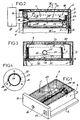
- the reference numeral 2 denotes, so general, an isothermal container 2 with a front door 3 and whose cavity internal is provided with slides, respectively lateral 4 and posterior 5, in which the edges, respectively lateral and posterior, from the bottom 6 of a drawer 7.
- This drawer divides the internal cavity of the container in an upper cryogenic compartment A and a compartment lower B for storage of fresh or frozen products.
- the drawer 7 has a front wall 8, capable of being fitted into an appropriate rebate of the container, and its bottom 6 is integral with a parallelepipedic tank 9 in form of box open upwards and whose upper opening is closed by a sheet 10, porous to gas but not to dry ice.
- the drawer is, for example, made by rotational molding of polyethylene and its hollow walls are filled with an insulating material, such than polyurethane foam 12.
- Room C communicates with the exterior by an opening 14, visible in FIG. 1, formed in the wall front 8 of the drawer.
- the gas accumulation chamber D it communicates with the outside through an opening 15, formed in the same wall 8.
- the tank 9 is equipped with a jet breaker 20 which is consisting of a tubular mesh 21 of pressure-resistant material, extending longitudinally inside the tank. Its anterior end is fixed on the internal face of the front wall 8, in the extension of the opening 14, for example by a flange 22. The other end of the jet breaker is closed and shaped as lug 23. This is fixed by a screw transverse not shown, on a step 24 projecting from the bottom of the tank and disposed near the rear wall 6a of this tank.
- Leg 23 is advantageously formed by flattening the tubular mesh in one of its diametrical plans.
- This tubular mesh is crossed by meshes 25.
- it may consist of metallic fabric, metallic fabric, metal deployed or by a perforated sheet.
- the perforations 25 are distributed in the part of the tubular mesh 21 which forms opposite the bottom 6 of the tank, that is to say substantially on its half lower, which implies that its upper part has no perforations.
- the trellis tubular 21 is constituted by a metallic fabric, bent to form a sleeve whose longitudinal edges are connected by a few points of solder 26.
- the upper part of the body, thus obtained, is covered by a semi-cylindrical cover 27, formed by a metal sheet which, after putting in shape, is fixed to the canvas by welds 28.
- the metal canvas is also welded to the flange 22, so as to form an assembly monolithic with this flange.
- the S1 / S2 ratio between, respectively, the total area perforated S1 of the meshes 25 used and the surface S2 of the cylindrical part tubular mesh allowing snow to pass, is between 0.45 and 0.8, and that whatever the dimension of the meshes which is defined according mechanical strength of the jet breaker.
- the pressurized jet emitted by the injector 18 remaining outside the jetbreaker is distributed longitudinally inside the body tubular of the breakwater 20 where it immediately turns into snow and gas. Due to its rigid structure, the jet breaker absorbs without deformation the forces resulting from this projection, and already reduced by the relaxation immediate. Furthermore, the non-perforated part, constituted by the cover 27, opposes any upward projection, in the direction of the sheet 10, and therefore prevents it, which is more fragile, from being subjected to accelerating forces its wear by abrasion.
- the gas escapes from the tank through the sheet 10, as shown in arrow 33, and from there goes to room D where it is sucked by means connected to the opening 15 formed in the wall frontal.
- the jet breaker is inexpensive and its low cost is more than offset by longer service life of the drawer, since, during repeated injections, its resistance is not affected and therefore can be used safely for many fills.
- the jet breaker is porous to snow throughout its periphery.
- it can be juxtaposed with another jet breaker, arranged in the same bin or in a neighboring bin.
Landscapes
- Engineering & Computer Science (AREA)
- Chemical & Material Sciences (AREA)
- Chemical Kinetics & Catalysis (AREA)
- Combustion & Propulsion (AREA)
- Physics & Mathematics (AREA)
- Mechanical Engineering (AREA)
- Thermal Sciences (AREA)
- General Engineering & Computer Science (AREA)
- Carbon And Carbon Compounds (AREA)
- Filling Or Discharging Of Gas Storage Vessels (AREA)
- Buffer Packaging (AREA)
- Accommodation For Nursing Or Treatment Tables (AREA)
Abstract
Description
L'invention concerne le domaine des conteneurs isothermiques comprenant, au-dessus d'un compartiment de conservation, un compartiment cryogénique pour le stockage de neige carbonique assurant la conservation des produits frais ou surgelés.The invention relates to the field of isothermal containers comprising, above a storage compartment, a cryogenic compartment for the storage of dry ice ensuring the conservation of fresh or frozen products.
Elle concerne plus particulièrement les compartiments cryogéniques dont la face avant est équipée d'au moins une ouverture pouvant être raccordée à l'injecteur d'un appareil d'injection de dioxyde de carbone en phase liquide, et d'au moins une ouverture pouvant être raccordée à une source d'aspiration pour récupérer le gaz carbonique, pendant la formation de la neige.It relates more particularly to the compartments cryogenic whose front face is equipped with at least one opening connectable to the injector of a dioxide injection device carbon in liquid phase, and at least one opening which can be connected to a suction source to recover carbon dioxide, during snow formation.
En général, pour permettre le nettoyage du compartiment cryogénique, celui-ci est constitué par un bac amovible ou par un tiroir, ce bac ou tiroir étant monté coulissant dans des glissières ménagées dans la paroi interne du conteneur.In general, to allow cleaning of the compartment cryogenic, this consists of a removable tray or a drawer, this tray or drawer being slidably mounted in slides arranged in the inner wall of the container.
Lors du chargement du compartiment cryogénique, la pression d'injection du dioxyde de carbone en phase liquide est de l'ordre de 15 à 25 bars. Pour éviter que cette pression endommage le compartiment, il est connu, par exemple par la demande de brevet français 2 706 920, de réaliser le bac en métal et de disposer dans celui-ci une ou plusieurs parois déflectrices qui réduisent la violence des jets de dioxyde de carbone en phase liquide sortant de buses d'injection disposées dans le compartiment. Une telle solution est onéreuse et n'est pas applicable aux bacs isothermiques en matière synthétique, plus adaptés à la conservation des produits frais, car ne nécessitant pas d'écran isolant supplémentaire pour limiter le rayonnement froid généré par le fond d'un bac métallique.When loading the cryogenic compartment, the pressure carbon dioxide injection in the liquid phase is around 15 to 25 bars. To prevent this pressure from damaging the compartment, it is known, for example from French patent application 2,706,920, from make the metal tray and have one or more walls in it deflectors that reduce the violence of carbon dioxide jets by liquid phase leaving injection nozzles arranged in the compartment. Such a solution is expensive and is not applicable to tanks isothermal synthetic material, more suitable for the conservation of fresh products because they do not require an additional insulating screen for limit the cold radiation generated by the bottom of a metal container.
Les demandes de brevets français 2 751 623 et 2 752 049, au nom de la déposante, décrivent de tels bacs ou tiroirs équipés d'une nappe de rétention de la neige carbonique. Cette nappe, qui est poreuse au gaz et non à la neige carbonique, est renforcée par un grillage métallique. L'injection est réalisée au moyen d'un équipement extérieur dont l'unique injecteur est disposé dans l'ouverture frontale du compartiment. Lors de l'injection du dioxyde de carbone en phase liquide, et indépendamment des efforts communiqués aux parois et à la nappe, dont l'usure est assez rapide, le jet perturbe la formation de la neige carbonique qui s'amasse localement et ne se répartit pas sur tout le fond du bac. Cela réduit la surface d'échange avec le compartiment de conservation et modifie donc les conditions de conservation.French patent applications 2,751,623 and 2,752,049, to name of the applicant, describe such bins or drawers fitted with a tablecloth dry ice retention. This tablecloth, which is porous with gas and No to dry ice, is reinforced by a metallic mesh. The injection is carried out using external equipment, the only one injector is arranged in the front opening of the compartment. During injection of carbon dioxide in the liquid phase, and independently of forces communicated to the walls and the sheet, the wear of which is fairly fast, the jet disturbs the formation of carbon dioxide snow which collects locally and does not spread over the entire bottom of the tank. This reduces the exchange surface with the storage compartment and therefore modifies storage conditions.
La présente invention a pour objet de remédier à cet inconvénient en fournissant un dispositif brise-jet pour bac ou tiroir de compartiment cryogénique alimentable par une buse extérieure, réduisant les effets de la pression sur le bac et de l'abrasion sur la paroi de rétention de la neige, mais aussi améliorant le remplissage en neige.The object of the present invention is to remedy this disadvantage by providing a spray breaker for a tray or drawer cryogenic compartment supplied by an external nozzle, reducing the effects of pressure on the tank and abrasion on the retention wall snow, but also improving snow filling.
A cet effet, dans le tiroir selon l'invention, le brise-jet est constitué par un treillis tubulaire en matériau résistant à la pression qui, disposé dans la chambre de stockage de la neige, est dans le prolongement de l'ouverture pour l'injecteur d'un appareil d'injection, est lié à la paroi frontale de ce tiroir par l'une de ses extrémités, est fermé à son autre extrémité et comporte, au moins dans une partie de sa paroi, des mailles, formant un réseau lacunaire régulier laissant passer le gaz mais aussi la neige se formant à l'intérieur du treillis.To this end, in the drawer according to the invention, the jet breaker is consisting of a tubular mesh of pressure-resistant material which, arranged in the snow storage chamber, is an extension of the opening for the injector of an injection device, is linked to the wall front of this drawer by one of its ends, is closed at its other end and comprises, at least in part of its wall, meshes, forming a regular lacunar network letting pass the gas but also the snow forming inside the trellis.
Ainsi, lors de l'injection du dioxyde de carbone en phase liquide dans le compartiment cryogénique, la pression du jet est absorbée par le treillis tubulaire, de sorte que les efforts perçus par les parois sont considérablement réduits. Sous l'effet de la détente, le dioxyde de carbone liquide se transforme, à l'intérieur du brise-jet, en neige carbonique qui, sous l'effet de la pression résiduelle, passe à travers les passages libres du treillis tubulaire et se répartit uniformément sur le fond du compartiment.So when injecting carbon dioxide in the liquid phase in the cryogenic compartment, the jet pressure is absorbed by the tubular mesh, so that the forces perceived by the walls are considerably reduced. Under the effect of expansion, carbon dioxide liquid is transformed, inside the jet breaker, into carbon dioxide snow which, under the effect of the residual pressure, passes through the free passages of the tubular mesh and is distributed evenly over the bottom of the compartment.
Avantageusement, le rapport S1/S2 entre la surface perforée S1 et la surface S2 de la partie laissant passer la neige du treillis tubulaire est compris entre 0,45 et 0,8.Advantageously, the ratio S1 / S2 between the perforated surface S1 and the surface S2 of the part allowing the snow to pass through the tubular trellis is between 0.45 and 0.8.
En effet, il s'est révélé qu'un rapport surface de vide S1/surface pleine S2 inférieur à 0,45 entraínait des pertes de rendement dans la formation de la neige carbonique.Indeed, it turned out that a vacuum area S1 / area ratio full S2 less than 0.45 resulted in yield losses in the carbon dioxide snow formation.
Dans une forme d'exécution, le treillis tubulaire est muni de mailles sur toute sa périphérie et comporte, sur sa partie supérieure et sur toute sa longueur, un capot semi cylindrique d'obturation des mailles correspondantes.In one embodiment, the tubular trellis is provided with mesh over its entire periphery and has, on its upper part and on its entire length, a semi-cylindrical mesh cover corresponding.
Ce capot s'oppose à la sortie de la neige vers le haut, en direction de la nappe poreuse au gaz et s'oppose donc à son colmatage par la neige, ce qui garantit l'évacuation du gaz. Il favorise également la distribution de la neige sur tout le fond du compartiment cryogénique.This hood opposes the exit of the snow upwards, in direction of the porous sheet of gas and therefore opposes its clogging by snow, which guarantees the evacuation of gas. It also promotes snow distribution over the entire bottom of the cryogenic compartment.
D'autres caractéristiques et avantages ressortiront de la
description qui suit en référence au dessin schématique annexé
représentant une forme d'exécution du dispositif brise-jet dans le cas de
son application à un conteneur équipé d'un bac tiroir.
Dans ce dessin, la référence numérique 2 désigne, de manière
générale, un conteneur isothermique 2 à porte frontale 3 et dont la cavité
interne est munie de glissières, respectivement latérales 4 et postérieure 5,
dans lesquelles peuvent s'engager les bords, respectivement latéraux et
postérieur, du fond 6 d'un tiroir 7. Ce tiroir divise la cavité interne du
conteneur en un compartiment cryogénique supérieur A et un compartiment
inférieur B de conservation de produits frais ou surgelés.In this drawing, the reference numeral 2 denotes, so
general, an isothermal container 2 with a
Dans la forme d'exécution représentée, le tiroir 7 comporte une
paroi frontale 8, apte à venir s'encastrer dans une feuillure appropriée du
conteneur, et son fond 6 est solidaire d'un bac parallélépipédique 9 en
forme de boíte ouverte vers le haut et dont l'ouverture supérieure est
obturée par une nappe 10, poreuse au gaz mais non à la neige carbonique.In the embodiment shown, the
Le tiroir est, par exemple, réalisé par roto moulage de
polyéthylène et ses parois creuses sont remplies par un matériau isolant, tel
que de la mousse de polyuréthanne 12.The drawer is, for example, made by rotational molding of
polyethylene and its hollow walls are filled with an insulating material, such
than
Le bac 9, dont la cavité interne constitue la chambre C de
stockage de la neige carbonique, est moins haut et moins large que le
compartiment A dans lequel il est disposé, de manière à ménager dans ce
compartiment une chambre D d'accumulation du gaz pendant la phase
d'injection du dioxyde de carbone, mais aussi lors de la sublimation de la
neige carbonique pendant la conservation. La chambre C communique avec
l'extérieur par une ouverture 14, visible figure 1, ménagée dans la paroi
frontale 8 du tiroir. Quant à la chambre D d'accumulation du gaz, elle
communique avec l'extérieur par une ouverture 15, ménagée dans la même
paroi 8.The
Ces deux ouvertures sont obturables, soit par un bouchon, soit
simplement par des joints 16 portés par la porte frontale 3 et venant en
appui sur la paroi 8, lors de la fermeture de la porte.These two openings can be closed either with a plug or
simply by
Selon l'invention, le bac 9 est équipé d'un brise-jet 20 qui est
constitué par un treillis tubulaire 21 en matériau résistant à la pression,
s'étendant longitudinalement à l'intérieur du bac. Son extrémité antérieure
est fixée sur la face interne de la paroi frontale 8, dans le prolongement de
l'ouverture 14, par exemple par une bride 22. L'autre extrémité du brise-jet
est fermée et conformée en patte 23. Celle-ci est fixée, par une vis
transversale non représentée, sur un redan 24 saillant du fond du bac et
disposé à proximité de la paroi arrière 6a de ce bac. La patte 23 est
avantageusement formée par aplatissement du treillis tubulaire dans l'un de
ses plans diamétraux.According to the invention, the
Ce treillis tubulaire est traversé par des mailles 25. Selon les
formes d'exécution, et en fonction des pressions d'injection utilisées, il
peut être constitué par un tissu métallique, une toile métallique, du métal
déployé ou par une tôle perforée.This tubular mesh is crossed by
Suivant une caractéristique essentielle de l'invention, les
perforations 25 sont réparties dans la partie du treillis tubulaire 21 qui fait
vis à vis au fond 6 du bac, c'est-à-dire sur sensiblement sa moitié
inférieure, ce qui implique que sa partie supérieure ne comporte pas de
perforations.According to an essential characteristic of the invention, the
Dans la forme d'exécution représentée figure 4, le treillis
tubulaire 21 est constitué par une toile métallique, cintrée pour former un
manchon dont les bords longitudinaux sont reliés par quelques points de
soudure 26. La partie supérieure du corps, ainsi obtenu, est recouverte par
un capot semi cylindrique 27, formé par une tôle métallique qui, après mise
en forme, est fixée sur la toile par des soudures 28. La toile métallique est
également soudée sur la bride 22, de manière à former un ensemble
monolithique avec cette bride.In the embodiment shown in Figure 4, the trellis
tubular 21 is constituted by a metallic fabric, bent to form a
sleeve whose longitudinal edges are connected by a few points of
Le rapport S1/S2 entre, respectivement la surface totale
perforée S1 des mailles 25 utilisées et la surface S2 de la partie cylindrique
du treillis tubulaire laissant passer la neige, est compris entre 0,45 et 0,8,
et cela quelle que soit la dimension des mailles qui est définie en fonction
de la résistance mécanique du brise-jet.The S1 / S2 ratio between, respectively, the total area
perforated S1 of the
Lorsqu'il est procédé au remplissage du bac au moyen d'un
appareil 17, distribuant par un injecteur 18, une quantité dosée de dioxyde
de carbone en phase liquide, le jet sous pression émis par l'injecteur 18
restant hors du brise jet se répartit longitudinalement à l'intérieur du corps
tubulaire du brise-jet 20 où il se transforme immédiatement en neige et en
gaz. En raison de sa structure rigide, le brise jet absorbe sans déformation
les efforts résultant de cette projection, et déjà réduits par la détente
immédiate. Par ailleurs, la partie non perforée, constituée par le capot 27,
s'oppose à toute projection vers le haut, en direction de la nappe 10, et
évite donc que celle-ci, plus fragile, soit soumise à des efforts accélérant
son usure par abrasion.When the tank is filled with a
Sous l'effet de la pression, la neige traverse les mailles 25 du
brise jet et se répartit uniformément sur le fond du bac, comme montré en
31 à la figure 3. Seule, une zone 32, disposée immédiatement sous le
brise-jet ne comporte pas de neige, puisqu'elle est chassée par le souffle de
la neige et du gaz passant à travers le brise-jet, mais la surface ainsi
délaissée est peu importante par rapport à la surface totale du bac dans
laquelle la neige se répartit uniformément. Par effet d'accumulation la neige
se répartit au-dessus du brise-jet.Under the effect of the pressure, the snow crosses the
Pendant l'injection, le gaz s'échappe du bac par la nappe 10,
comme le montre la flèche 33, et de là va dans la chambre D où il est
aspiré par des moyens raccordés à l'ouverture 15 ménagés dans la paroi
frontale.During the injection, the gas escapes from the tank through the
A titre d'exemple de réalisation il est décrit les conditions de remplissage d'un tiroir comportant un bac parallélépipédique ayant pour dimensions intérieures 407 x 533 x 90 mm et une capacité de 19,5 dm3 et dans lequel le brise-jet, ayant un diamètre de 35 mm et une longueur de 530 mm, était réalisé dans une toile métallique ayant des mailles carrées de 1,5 mm formées par des fils dont l'épaisseur était de 0,5 mm. La nappe 10 disposée en dessus de l'ouverture du bac était constituée par un média filtrant en fibres de polypropylène liées thermiquement et résistant à l'humidité. Les caractéristiques de cette nappe étaient les suivantes :
- Poids 200g / m2
Epaisseur 15 mm- Classification G3
- Rendement gravimétrique 85%
- Rendement opacimétrie moins de 20 %
- Capacité de colmatage 600 g / m2
- Weight 200g / m 2
-
Thickness 15 mm - G3 classification
- Gravimetric efficiency 85%
- Opacimetry yield less than 20%
- Clogging capacity 600 g / m 2
L'injection de dioxyde de carbone en phase liquide sous une pression de 21 Bars, avec un débit de 19,2 Kg / mn pendant 30 secondes permet d'obtenir 4,3 Kilogrammes de neige, soit un rendement de 44,79 %.The injection of carbon dioxide in liquid phase under a pressure of 21 Bars, with a flow rate of 19.2 Kg / min for 30 seconds produces 4.3 Kilograms of snow, giving a yield of 44.79%.
Divers essais ont permis de constater que ce rendement variait
entre 42 et 46 % selon le débit et la pression d'injection du dioxyde de
carbone en phase liquide, des caractéristiques de la nappe 10 et des
conditions de température de la ligne de remplissage et du bac.Various tests have shown that this yield varied
between 42 and 46% depending on the flow rate and the injection pressure of the dioxide
carbon in the liquid phase, characteristics of the
En raison de sa simplicité, le brise-jet est peu onéreux et son
faible coût est largement compensé par une plus grande durée d'utilisation
du tiroir, puisque, lors des injections répétées, sa résistance n'est pas
affectée et qu'il peut donc être utilisé sans risque pour de très nombreux
remplissages. Dans certaines applications, et par exemple lorsqu'il est très
éloigné de la nappe 10, le brise-jet est poreux à la neige sur toute sa
périphérie. Par ailleurs, il peut être juxtaposé à un autre brise-jet, disposé
dans le même bac ou dans un bac voisin.Because of its simplicity, the jet breaker is inexpensive and its
low cost is more than offset by longer service life
of the drawer, since, during repeated injections, its resistance is not
affected and therefore can be used safely for many
fills. In some applications, for example when it is very
away from the
Claims (5)
Applications Claiming Priority (2)
| Application Number | Priority Date | Filing Date | Title |
|---|---|---|---|
| FR9803221 | 1998-03-10 | ||
| FR9803221A FR2776056B1 (en) | 1998-03-10 | 1998-03-10 | JET BREAKER FOR CRYOGENIC COMPARTMENT OF ISOTHERMIC CONTAINER |
Publications (2)
| Publication Number | Publication Date |
|---|---|
| EP0942244A1 true EP0942244A1 (en) | 1999-09-15 |
| EP0942244B1 EP0942244B1 (en) | 2003-04-16 |
Family
ID=9524114
Family Applications (1)
| Application Number | Title | Priority Date | Filing Date |
|---|---|---|---|
| EP19990420062 Expired - Lifetime EP0942244B1 (en) | 1998-03-10 | 1999-03-09 | Isothermal container |
Country Status (5)
| Country | Link |
|---|---|
| EP (1) | EP0942244B1 (en) |
| DE (1) | DE69906854T2 (en) |
| ES (1) | ES2194429T3 (en) |
| FR (1) | FR2776056B1 (en) |
| PT (1) | PT942244E (en) |
Cited By (11)
| Publication number | Priority date | Publication date | Assignee | Title |
|---|---|---|---|---|
| EP1724538A1 (en) * | 2005-05-20 | 2006-11-22 | Olivo | Logistic system for the transportation of fresh or frozen products |
| FR2891354A1 (en) * | 2005-09-28 | 2007-03-30 | Air Liquide | Cryogenic reservoir for isothermal container, has carbon dioxide snow receptacle comprising perforated zone at upper surface for evacuating gas generated inside receptacle, and lid integrated to upper surface of receptacle |
| EP2336684A1 (en) | 2009-12-21 | 2011-06-22 | Messer France S.A.S. | Filling device for filling a coolant container compartment attached to a coolant container with a cryogenic coolant |
| WO2012107518A3 (en) * | 2011-02-09 | 2012-11-01 | Acp Belgium N.V. | System for cooling medium introduction into a container |
| DE102014008902A1 (en) | 2014-06-14 | 2015-12-17 | Gebhardt Transport- Und Lagersysteme Gmbh | Thermosperre for cooling tank |
| DE102015009647B3 (en) * | 2015-07-24 | 2016-10-06 | Messer France S.A.S | Filling device for filling a cooling tank associated with a refrigerant receiving compartment with a cryogenic refrigerant |
| DE102015009645A1 (en) | 2015-07-24 | 2017-01-26 | Messer France S.A.S | Filling device for filling a cooling tank associated with a refrigerant receiving compartment with a cryogenic refrigerant |
| EP3246642A1 (en) | 2016-05-19 | 2017-11-22 | Olivo | Cryogenic tank for cooling compartment of isothermal container |
| WO2020120433A1 (en) | 2018-12-12 | 2020-06-18 | Messer Group Gmbh | Device for charging a refrigerant-receiving compartment of a cooling container with dry ice |
| WO2020186337A1 (en) * | 2019-03-20 | 2020-09-24 | Cryologistics Refrigeration Technologies Ltd. | Passive refrigeration system using carbon dioxide snow |
| DE102019005745A1 (en) * | 2019-08-16 | 2021-02-18 | Messer Group Gmbh | Device and method for metering carbon dioxide snow |
Families Citing this family (2)
| Publication number | Priority date | Publication date | Assignee | Title |
|---|---|---|---|---|
| FR2836543B1 (en) * | 2002-02-25 | 2004-04-16 | Olivo | REINFORCED TANK FOR CRYOGENIC COMPARTMENT OF INSULATED CONTAINER |
| FR2839774B1 (en) | 2002-05-17 | 2004-07-02 | Olivo | ADAPTABLE DIFFUSION CRYOGENIC TANK FOR INSULATED CONTAINER |
Citations (5)
| Publication number | Priority date | Publication date | Assignee | Title |
|---|---|---|---|---|
| US4376511A (en) * | 1981-04-01 | 1983-03-15 | Franklin Jr Paul R | CO2 Snow forming copper line |
| FR2706990A1 (en) * | 1993-06-23 | 1994-12-30 | Carboxyque Francaise | |
| EP0721801A1 (en) * | 1994-12-15 | 1996-07-17 | Hughes Aircraft Company | C02 jet spray nozzle with multiple orifices |
| EP0823600A2 (en) * | 1996-07-30 | 1998-02-11 | Olivo | Isothermal container with cold storage |
| FR2752456A1 (en) * | 1996-08-13 | 1998-02-20 | Grandi Rene Vincent | Thermally regulated transfer arrangement for refrigerated products from vat to storage chamber |
Family Cites Families (2)
| Publication number | Priority date | Publication date | Assignee | Title |
|---|---|---|---|---|
| FR2706920A1 (en) | 1993-06-24 | 1994-12-30 | Bricaud Motor | Clamp for gripping, handling and positioning constructional elements such as kerbstones |
| FR2751623B1 (en) | 1996-07-23 | 1998-09-04 | Olivo | INSULATED CONTAINER WITH REFRIGERANT CONTAINER |
-
1998
- 1998-03-10 FR FR9803221A patent/FR2776056B1/en not_active Expired - Fee Related
-
1999
- 1999-03-09 ES ES99420062T patent/ES2194429T3/en not_active Expired - Lifetime
- 1999-03-09 PT PT99420062T patent/PT942244E/en unknown
- 1999-03-09 DE DE1999606854 patent/DE69906854T2/en not_active Expired - Lifetime
- 1999-03-09 EP EP19990420062 patent/EP0942244B1/en not_active Expired - Lifetime
Patent Citations (5)
| Publication number | Priority date | Publication date | Assignee | Title |
|---|---|---|---|---|
| US4376511A (en) * | 1981-04-01 | 1983-03-15 | Franklin Jr Paul R | CO2 Snow forming copper line |
| FR2706990A1 (en) * | 1993-06-23 | 1994-12-30 | Carboxyque Francaise | |
| EP0721801A1 (en) * | 1994-12-15 | 1996-07-17 | Hughes Aircraft Company | C02 jet spray nozzle with multiple orifices |
| EP0823600A2 (en) * | 1996-07-30 | 1998-02-11 | Olivo | Isothermal container with cold storage |
| FR2752456A1 (en) * | 1996-08-13 | 1998-02-20 | Grandi Rene Vincent | Thermally regulated transfer arrangement for refrigerated products from vat to storage chamber |
Cited By (21)
| Publication number | Priority date | Publication date | Assignee | Title |
|---|---|---|---|---|
| EP1724538A1 (en) * | 2005-05-20 | 2006-11-22 | Olivo | Logistic system for the transportation of fresh or frozen products |
| FR2886002A1 (en) * | 2005-05-20 | 2006-11-24 | Olivo Sa | ISOTHERMAL CONTAINER AND DEVICE FOR INJECTING A REFRIGERANT IN THIS CONTAINER |
| FR2891354A1 (en) * | 2005-09-28 | 2007-03-30 | Air Liquide | Cryogenic reservoir for isothermal container, has carbon dioxide snow receptacle comprising perforated zone at upper surface for evacuating gas generated inside receptacle, and lid integrated to upper surface of receptacle |
| WO2007036656A1 (en) * | 2005-09-28 | 2007-04-05 | L'air Liquide Societe Anonyme Pour L'etude Et L'exploitation Des Procedes Georges Claude | Dual-compartment carbon dioxide snow receptacle for isothermal containers |
| EP1934537B1 (en) | 2005-09-28 | 2016-03-09 | L'AIR LIQUIDE, Société Anonyme pour l'Etude et l'Exploitation des Procédés Georges Claude | Dual-compartment carbon dioxide snow receptacle for isothermal containers |
| EP2336684A1 (en) | 2009-12-21 | 2011-06-22 | Messer France S.A.S. | Filling device for filling a coolant container compartment attached to a coolant container with a cryogenic coolant |
| WO2011076701A1 (en) | 2009-12-21 | 2011-06-30 | Messer France S.A.S. | Filling device for filling a coolant receptacle associated with a cooling tank having a cryogenic coolant |
| WO2012107518A3 (en) * | 2011-02-09 | 2012-11-01 | Acp Belgium N.V. | System for cooling medium introduction into a container |
| BE1020015A5 (en) * | 2011-02-09 | 2013-03-05 | Acp Belgium N V | SYSTEM FOR INSERTING COOLANT TO A CONTAINER. |
| DE102014008902A1 (en) | 2014-06-14 | 2015-12-17 | Gebhardt Transport- Und Lagersysteme Gmbh | Thermosperre for cooling tank |
| DE102015009647B3 (en) * | 2015-07-24 | 2016-10-06 | Messer France S.A.S | Filling device for filling a cooling tank associated with a refrigerant receiving compartment with a cryogenic refrigerant |
| DE102015009645A1 (en) | 2015-07-24 | 2017-01-26 | Messer France S.A.S | Filling device for filling a cooling tank associated with a refrigerant receiving compartment with a cryogenic refrigerant |
| WO2017017030A1 (en) | 2015-07-24 | 2017-02-02 | Messer France S.A.S. | Filling device for filling a coolant-receiving compartment associated with a cooling tank with a cryogenic coolant |
| DE102015009645B4 (en) | 2015-07-24 | 2020-01-16 | Messer France S.A.S | Filling device for filling a refrigerant receptacle assigned to a cooling container with a cryogenic refrigerant |
| EP3246642A1 (en) | 2016-05-19 | 2017-11-22 | Olivo | Cryogenic tank for cooling compartment of isothermal container |
| WO2020120433A1 (en) | 2018-12-12 | 2020-06-18 | Messer Group Gmbh | Device for charging a refrigerant-receiving compartment of a cooling container with dry ice |
| DE102018009755A1 (en) | 2018-12-12 | 2020-06-18 | Messer Group Gmbh | Device for loading a refrigerant storage compartment of a cooling container with dry ice |
| WO2020186337A1 (en) * | 2019-03-20 | 2020-09-24 | Cryologistics Refrigeration Technologies Ltd. | Passive refrigeration system using carbon dioxide snow |
| EP3942236A4 (en) * | 2019-03-20 | 2022-11-30 | Cryologistics Refrigeration Technologies Ltd. | Passive refrigeration system using carbon dioxide snow |
| DE102019005745A1 (en) * | 2019-08-16 | 2021-02-18 | Messer Group Gmbh | Device and method for metering carbon dioxide snow |
| WO2021032377A1 (en) | 2019-08-16 | 2021-02-25 | Messer Group Gmbh | Device for metering carbon dioxide snow |
Also Published As
| Publication number | Publication date |
|---|---|
| ES2194429T3 (en) | 2003-11-16 |
| EP0942244B1 (en) | 2003-04-16 |
| FR2776056B1 (en) | 2000-05-26 |
| PT942244E (en) | 2003-06-30 |
| DE69906854D1 (en) | 2003-05-22 |
| DE69906854T2 (en) | 2003-11-20 |
| FR2776056A1 (en) | 1999-09-17 |
Similar Documents
| Publication | Publication Date | Title |
|---|---|---|
| EP0942244B1 (en) | Isothermal container | |
| EP2845944B1 (en) | Ironing electrical appliance comprising a filter for retaining scale particles carried by the steam | |
| EP0735837B1 (en) | Automatic machine for the preparation of hot beverage infusions | |
| EP3064639B1 (en) | Ironing electrical appliance comprising a filter for retaining scale particles carried by the steam | |
| FR2535986A1 (en) | SIMPLIFIED WORK PIECE WASHER, AND CONTAINER AND FLUID CIRCULATION DEVICE FOR SAID WASHER | |
| EP3580385B1 (en) | Iron including a device for retaining scale particles transported by the steam | |
| EP0823600B1 (en) | Isothermal container with cold storage | |
| FR2920425A1 (en) | FILTER ASSEMBLY FOR A DOMESTIC WATER FILTRATION APPARATUS AND METHOD FOR FILTERING WATER USING THE APPARATUS | |
| EP0081417A1 (en) | Lockable container with one or several vertical compartments | |
| FR2497629A1 (en) | ||
| EP2032010B1 (en) | Vacuum cleaner | |
| CA2579194C (en) | Filtering element for liquids and filtering installation comprising same | |
| EP0777537B1 (en) | Facility for grinding and decontaminating waste, particularly hospital waste | |
| EP0740518A1 (en) | Cooking apparatus, such as deep fryer, comprising a cooking vapour condenser device | |
| EP3757279B1 (en) | Iron comprising a device for retaining scale particles carried by steam | |
| EP3040294B1 (en) | System for storing waste and percolating water | |
| FR2751623A1 (en) | Isothermic container with refrigerated chamber | |
| FR3031171A1 (en) | CRYOGENIC TANK FOR REFRIGERANT COMPARTMENT OF ISOTHERMAL CONTAINER | |
| FR2836543A1 (en) | Reinforced reservoir for a cryogenic compartment of an isothermal container | |
| FR2766383A1 (en) | Filter cartridge for fluid circulating in engine block | |
| EP0453339B1 (en) | Apparatus for the evacuation of gas from a container | |
| FR3004382A1 (en) | DISCONTINUOUS FRUIT PRESSURIZATION DEVICE | |
| WO2019138198A1 (en) | Water filtration module incorporating hollow-fibre filtration elements | |
| WO2014060694A1 (en) | Container for a liquid, comprising a pouch | |
| EP2584202A2 (en) | Filtering device for supply pipe of a swimming-pool pump |
Legal Events
| Date | Code | Title | Description |
|---|---|---|---|
| PUAI | Public reference made under article 153(3) epc to a published international application that has entered the european phase |
Free format text: ORIGINAL CODE: 0009012 |
|
| AK | Designated contracting states |
Kind code of ref document: A1 Designated state(s): BE DE ES FR GB IT PT |
|
| AX | Request for extension of the european patent |
Free format text: AL;LT;LV;MK;RO;SI |
|
| 17P | Request for examination filed |
Effective date: 20000313 |
|
| AKX | Designation fees paid |
Free format text: BE DE ES FR GB IT PT |
|
| GRAH | Despatch of communication of intention to grant a patent |
Free format text: ORIGINAL CODE: EPIDOS IGRA |
|
| RTI1 | Title (correction) |
Free format text: ISOTHERMAL CONTAINER |
|
| GRAH | Despatch of communication of intention to grant a patent |
Free format text: ORIGINAL CODE: EPIDOS IGRA |
|
| GRAA | (expected) grant |
Free format text: ORIGINAL CODE: 0009210 |
|
| AK | Designated contracting states |
Designated state(s): BE DE ES FR GB IT PT |
|
| REG | Reference to a national code |
Ref country code: GB Ref legal event code: FG4D Free format text: NOT ENGLISH |
|
| GBT | Gb: translation of ep patent filed (gb section 77(6)(a)/1977) |
Effective date: 20030416 |
|
| REF | Corresponds to: |
Ref document number: 69906854 Country of ref document: DE Date of ref document: 20030522 Kind code of ref document: P |
|
| REG | Reference to a national code |
Ref country code: PT Ref legal event code: SC4A Free format text: AVAILABILITY OF NATIONAL TRANSLATION Effective date: 20030509 |
|
| REG | Reference to a national code |
Ref country code: ES Ref legal event code: FG2A Ref document number: 2194429 Country of ref document: ES Kind code of ref document: T3 |
|
| PLBE | No opposition filed within time limit |
Free format text: ORIGINAL CODE: 0009261 |
|
| STAA | Information on the status of an ep patent application or granted ep patent |
Free format text: STATUS: NO OPPOSITION FILED WITHIN TIME LIMIT |
|
| 26N | No opposition filed |
Effective date: 20040119 |
|
| REG | Reference to a national code |
Ref country code: FR Ref legal event code: PLFP Year of fee payment: 18 |
|
| REG | Reference to a national code |
Ref country code: FR Ref legal event code: PLFP Year of fee payment: 19 |
|
| REG | Reference to a national code |
Ref country code: FR Ref legal event code: PLFP Year of fee payment: 20 |
|
| PGFP | Annual fee paid to national office [announced via postgrant information from national office to epo] |
Ref country code: GB Payment date: 20180316 Year of fee payment: 20 Ref country code: DE Payment date: 20180309 Year of fee payment: 20 |
|
| PGFP | Annual fee paid to national office [announced via postgrant information from national office to epo] |
Ref country code: PT Payment date: 20180216 Year of fee payment: 20 Ref country code: BE Payment date: 20180327 Year of fee payment: 20 Ref country code: FR Payment date: 20180329 Year of fee payment: 20 Ref country code: IT Payment date: 20180309 Year of fee payment: 20 |
|
| PGFP | Annual fee paid to national office [announced via postgrant information from national office to epo] |
Ref country code: ES Payment date: 20180427 Year of fee payment: 20 |
|
| REG | Reference to a national code |
Ref country code: DE Ref legal event code: R071 Ref document number: 69906854 Country of ref document: DE |
|
| REG | Reference to a national code |
Ref country code: GB Ref legal event code: PE20 Expiry date: 20190308 |
|
| PG25 | Lapsed in a contracting state [announced via postgrant information from national office to epo] |
Ref country code: GB Free format text: LAPSE BECAUSE OF EXPIRATION OF PROTECTION Effective date: 20190308 |
|
| REG | Reference to a national code |
Ref country code: BE Ref legal event code: MK Effective date: 20190309 |
|
| PG25 | Lapsed in a contracting state [announced via postgrant information from national office to epo] |
Ref country code: PT Free format text: LAPSE BECAUSE OF EXPIRATION OF PROTECTION Effective date: 20190410 |
|
| REG | Reference to a national code |
Ref country code: ES Ref legal event code: FD2A Effective date: 20200904 |
|
| PG25 | Lapsed in a contracting state [announced via postgrant information from national office to epo] |
Ref country code: ES Free format text: LAPSE BECAUSE OF EXPIRATION OF PROTECTION Effective date: 20190310 |