EP0941647A2 - Liaison de montage à quatre bras pour tondeuse - Google Patents
Liaison de montage à quatre bras pour tondeuse Download PDFInfo
- Publication number
- EP0941647A2 EP0941647A2 EP99102852A EP99102852A EP0941647A2 EP 0941647 A2 EP0941647 A2 EP 0941647A2 EP 99102852 A EP99102852 A EP 99102852A EP 99102852 A EP99102852 A EP 99102852A EP 0941647 A2 EP0941647 A2 EP 0941647A2
- Authority
- EP
- European Patent Office
- Prior art keywords
- mower
- link
- links
- housing
- prime mover
- Prior art date
- Legal status (The legal status is an assumption and is not a legal conclusion. Google has not performed a legal analysis and makes no representation as to the accuracy of the status listed.)
- Granted
Links
- 230000008878 coupling Effects 0.000 claims 7
- 238000010168 coupling process Methods 0.000 claims 7
- 238000005859 coupling reaction Methods 0.000 claims 7
- 239000012530 fluid Substances 0.000 description 2
- 239000011295 pitch Substances 0.000 description 2
- 230000006835 compression Effects 0.000 description 1
- 238000007906 compression Methods 0.000 description 1
- 230000002787 reinforcement Effects 0.000 description 1
- 230000000717 retained effect Effects 0.000 description 1
- 238000005096 rolling process Methods 0.000 description 1
Images


Classifications
-
- A—HUMAN NECESSITIES
- A01—AGRICULTURE; FORESTRY; ANIMAL HUSBANDRY; HUNTING; TRAPPING; FISHING
- A01D—HARVESTING; MOWING
- A01D34/00—Mowers; Mowing apparatus of harvesters
- A01D34/01—Mowers; Mowing apparatus of harvesters characterised by features relating to the type of cutting apparatus
- A01D34/412—Mowers; Mowing apparatus of harvesters characterised by features relating to the type of cutting apparatus having rotating cutters
- A01D34/63—Mowers; Mowing apparatus of harvesters characterised by features relating to the type of cutting apparatus having rotating cutters having cutters rotating about a vertical axis
- A01D34/64—Mowers; Mowing apparatus of harvesters characterised by features relating to the type of cutting apparatus having rotating cutters having cutters rotating about a vertical axis mounted on a vehicle, e.g. a tractor, or drawn by an animal or a vehicle
-
- A—HUMAN NECESSITIES
- A01—AGRICULTURE; FORESTRY; ANIMAL HUSBANDRY; HUNTING; TRAPPING; FISHING
- A01D—HARVESTING; MOWING
- A01D2101/00—Lawn-mowers
-
- Y—GENERAL TAGGING OF NEW TECHNOLOGICAL DEVELOPMENTS; GENERAL TAGGING OF CROSS-SECTIONAL TECHNOLOGIES SPANNING OVER SEVERAL SECTIONS OF THE IPC; TECHNICAL SUBJECTS COVERED BY FORMER USPC CROSS-REFERENCE ART COLLECTIONS [XRACs] AND DIGESTS
- Y10—TECHNICAL SUBJECTS COVERED BY FORMER USPC
- Y10S—TECHNICAL SUBJECTS COVERED BY FORMER USPC CROSS-REFERENCE ART COLLECTIONS [XRACs] AND DIGESTS
- Y10S56/00—Harvesters
- Y10S56/22—Underslung yieldable rotary mower
Definitions
- the present invention relates to a four bar mounting linkage for mounting a mower housing to a prime mover, such as a skid steer loader.
- the linkage controls pivoting of the mower housing about horizontal axes, and transfers weight to the prime mover as the mower housing pivots, as well as providing for automatic shut off of a motor driving mower cutter blades when the front of the housing tilts up a certain number of degrees or is raised a selected distance.
- U.S. Patent No. 5,435,117 shows a rotary mower mounted onto a skid steer loader with an automatic engine cutoff.
- the mounting linkage is connected to the mower housing about a single horizontal pivot axis.
- the present invention relates to a four bar linkage for mounting a mower of the type shown in patent 5,435,117, to include the feature of the automatic shut off when the mower is raised a predetermined distance, and also provides for a mounting that results in weight transfer and limits the amount of rearward tilting of the mower.
- the present invention relates to a rotary mower that has a housing with a power unit on the housing.
- the mower is adapted to be mounted onto a skid steer loader, through a four bar linkage that provides for controlled up and down and side to side (roll) movement of the mower, preferably, in one aspect of the invention, with weight transfer to the prime mover or skid steer loader as the mower housing is lifted by the links, or when the front tilts down.
- the linkage also permits some floating of the mower to accommodate ground irregularities by providing for limited telescoping of the upper links of the four bar linkage assembly.
- the four bar linkage controls the pivoting of the housing about a horizontal axis a selected amount, so that the mower can tilt when going over a mound or when starting up a hill.
- the linkage also permit the mower to move over irregularities in the ground.
- an automatic shut off linkage will shut off the drive power to the mower.
- the four bar linkage comprises illustratively, a pair of bottom links, which, as shown, have first ends pivotally mounted to an attachment bracket that mounts on the prime mover. Opposite ends of the lower links are pivotally mounted to the mower housing. There are lower links on each of the opposite sides of the mower housing. Upper links have a sliding and pivoting connection to the mower housing and the opposite ends pivot to the prime mover attachment bracket. Illustratively, a spring is provided between the forward ends of each upper link and the pivot connection to the mower housing, which permits the front end of the mower to float downwardly on downhill inclines. The upper link stops downwardly pivoting of the front of the mower housing to prevent the front end from rolling under the support linkage.
- the bracket is mounted on an attachment plate provided on the lift arms of the skid steer loader, which is pivotable about a horizontal axis using a hydraulic cylinder.
- the mower can be tilted down by raising the arms of the skid steer loader so that the attachment plate is raised, and then tilting the attachment plate downwardly.
- the power for the mower motor is from the hydraulic system of the skid steer loader on which the mower is mounted.
- the front of the mower has depending chains that are fastened in place in a unique manner and serve as a front deflector shield.
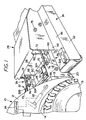
- a skid steer loader shown fragmentarily at 10 is a conventional loader that has lift arms 12 mounted onto a frame 14 at the rear portions of the frame (not shown).
- the lift arms 12 are operable to raise and lower as desired.
- the skid steer loader 10 has a plurality of wheels 16, and is movable over the ground.
- the skid steer loader 10 shown in the drawings has a front attachment plate 18 that is pivotally mounted about an axis 20 to the lower ends of the lift arms 12, and can be controlled as to its angle utilizing a hydraulic actuator shown only schematically in dotted lines at 22 from suitable controls represented at 24 which are accessible to an operator in the skid steer loader cab.
- the controls 24 receive hydraulic power from a pump driven from the engine of the skid steer loader, and are used to provide hydraulic power to a front mounted rotary mower indicated at 26.
- the rotary mower 26 has a mounting bracket 28 that attaches to the attachment plate 18 of the skid steer loader in a conventional manner.
- the mounting bracket 28, as shown, has a pair of spaced apart linkage mounting brackets 32, 32, each of which is comprised of two spaced plates 32A and 32B that are used for mounting a four bar linkage 36 on each side of the housing.
- a mower housing 38 is mounted on the four bar linkage 36.
- the housing 38 has a top plate 48 that supports depending walls forming a skirt 52 on the sides of the housing 38.
- a rotary mower blade 42 is mounted below top plate 48 and within skirt 52.
- the blade 42 is driven from a vertical shaft 44 of a gear box 43 that is mounted onto top plate 48 of the mower housing.
- the gear box 43 in turn is driven by a hydraulic motor 50 that is controlled through a suitable valve assembly 51.
- the valve 51 is connected to the hydraulic system of the prime mover or skid steer loader 10 through controls 24.
- the valve 51 is automatically shut off by a linkage actuated when the mower tilts relative to mounting bracket or is raised a selected amount.
- the valve control linkage will shut off the hydraulic motor 50 and discontinue driving of the rotary blade assembly 42 as will be explained.
- the housing 38 supports a roller 54 on the side walls at the rear edge of the mower for controlling spacing relative to the ground.
- a linkage support frame 53 is mounted on top plate 48 and comprises a housing that has a pair of sturdy outer side plates 56, 56 that are spaced apart and are joined by a rear wall 58 adjacent the mounting bracket 28.
- a separate inner support wall 59 (see Figure 3) is mounted adjacent to and spaced from each outer side wall 56 to provide a support for linkages 36 on both sides of the mower housing.
- the rear wall 58 has slots 60 defined on opposite sides thereof to permit the linkages 36 to extend to the linkage support frame 53, where the link of each linkage members are pivotally attached between the side walls 56 and the respective inner support wall 59.
- a cover 62 is mounted with hinges 64 to the top plate 48 of the housing 38.
- the cover 62 can be opened for servicing the four-bar linkage, or the hydraulic and drive components, including motor 50.
- the cover can be suitably latched in place.
- Each four bar linkage 36 comprises a lower mounting link 66, one on each of the opposite sides of the mower housing 38, and having first ends mounted between the side plates 32A and 32B through a suitable pivot pin 68 on each of the brackets 32.
- the forward ends of the lower links 66 are pivotally mounted as at 70 with suitable pivot pins between the side plates 56 and the respective adjacent inner plate 59.
- the pivot pins used can be mounted in hubs welded to the plates 56 and 59. Suitable reinforcements can be made as desired.
- Each of the linkages 36 further includes an upper link 72, on each of the opposite sides of the housing above the respective lower link 66.
- First ends of the upper links 72 are supported in the brackets 32 on suitable pivot pins 74.
- the links 72 have hub ends 75 that fit between the side plates 32A and 32B of each of the mounting brackets 32.
- the pivot pin 74 extend through the side plates of the respective brackets 32 in a suitable manner.
- a pivot bushing 76 has a support opening 78 and wiper seals 77 that slidably receive the cylindrical or circular cross section upper links or rods 72.
- the bushing 76 of each link is pivotally mounted in an outer support sleeve 78 that is welded to the respective plates 56 and 59.
- the bushing 76 can pivot about a horizontal axis.
- the bushing 76 is held in the sleeve 78 with washers 79 and removable capscrews 79A.
- the washers 79 are larger than the bushing 76 and engage recessed end surfaces of the sleeve 78 to axially position the bushing 76.
- the end portion of the links or rods 72 that protrude from the bushings 76 have collars 80 at the outer side of bushings 76 that support springs 82 between the collar 80 and a washer 84 that is secured to the end of each of the links 72 with a separate nut 85.
- Each spring 82 will permit some compression, when the respective link slides rearwardly through its bushings 76 so the washer 80 engages the housing 78. The spring 82 will compress when the front of the mower housing 40 tends to tilt downwardly.
- the lower links 66 carry stop plates 86 on the top of the links, which are aligned with the housings 78 for the bushings 76. When in the position shown in Figure 4, the stop plates 86 will engage the housings 78 and prevent further upward movement of the lower links 66 relative to the side plates 56, causing the mower to be lifted if the lower links are raised farther, or if the front of the mower housing tilts farther upwardly.
- At least one of the lower links 66 carries a stop plate 90 which is positioned to engage a pivoting lever 92 for shutting off the valve 51.
- the valve 51 as shown in Figure 5, is carried on the inside of wall 58.
- the lever 92 is pivotally mounted on a pin 93 and is loaded with a spring 94 that is strong enough to move the lever 92 to its dotted position in Figure 5 when the links 66 are in normal working position and the main power source is turned off with a valve in the operator's compartment, which provides hydraulic fluid under pressure to valve 51.
- This is the "on" position of the valve 51, which in turn controls flow of hydraulic fluid under pressure to drive motor 50 when the operator's valve is on. The operator can turn the mower motor off even when valve 51 is on.
- FIG. 2 A normal position for operating the mower is shown in Figure 2, the lower and upper links substantially horizontal and generally parallel.
- the spring 82 is in position so that the mower front edge can move down as the spring 82 compresses.
- the mower can also tilt upwardly slightly as the links 72 slide through bushing 76. This lets the mower move across ground contours without affecting operating.
- the links 66 and 72 are not links that remain at the same spacing when the mower raises, in that the upper links 72 are shorter between its pivot points than the lower links 66, and the arrangement of the pivot points is such that the differential movement will cause the links to move together and the stop member engaging the housing 78 will cause lifting of the mower. Further, the telescoping of the links 72 in the sleeves 76 permits some fore and aft tilting (changes in pitch) of the mower during operation as described, for following contours of the ground. The mower can pivot about a fore and aft axis (roll) so one side can raise relative to the other to follow contours in the ground.
- the links 66 will engage the top plate 48 and movement of the front end of the mower downwardly will be stopped and load transferred to the lift arms of the loader.
- the attachment bracket on the loader will also tilt about axis 20.
- the top of the bracket can be tilted forwardly along with raising the lift arms 12 to the position where the links are as shown in Figure 4 with bottom edge of the mower skirt parallel to the ground. As can be seen in such position the valve will be shut off.
- mounting bracket 28 The amount of tilt of mounting bracket 28 is limited by hub end 75 contacting the top of link 66. This also limits how far the front of the mower can rotate upward.
- a channel member 100 has a horizontal lower wall 101 with a plurality of spaced, cross slots 102 formed along the length of the channel (see Figures 7 and 8). Slots 102 are of sufficient length and width to receive a link 104 of a multi-link depending chain 106. The chains 106 will hang down below the channel member 100.
- Each of the links 104 for each chain 106 is moved up from the bottom of the channel 100 through one of the openings 102, and a rod 108, is passed through the upper enclosed loop portion of each link 104 so that each link 104 is retained in the channel 100 and cannot be pulled down through the slot 102.
- Each of the chains 106 is of sufficient length so that when upper end link 104 is in place in the channel 100, the lower end of the chain will be the proper length for use.
- the rods 108 are held in place with a suitable lock tab 110, which is welded to the end of rod 108, and extends laterally.
- the lock tabs are secured to tabs 112 welded at the end of the channel 100 with capscrews 114.
- the rod 108 can be held in place in any suitable way so that it does not move longitudinally to release the chains 106.
- the chains 106 are very short lengths as shown.
- a three bar linkage, with a single link on either the top or bottom will work if desired.
Landscapes
- Life Sciences & Earth Sciences (AREA)
- Environmental Sciences (AREA)
- Harvester Elements (AREA)
Applications Claiming Priority (2)
| Application Number | Priority Date | Filing Date | Title |
|---|---|---|---|
| US09/033,382 US6116007A (en) | 1998-03-02 | 1998-03-02 | Four bar linkage mounting for mowers |
| US33382 | 1998-03-02 |
Publications (3)
| Publication Number | Publication Date |
|---|---|
| EP0941647A2 true EP0941647A2 (fr) | 1999-09-15 |
| EP0941647A3 EP0941647A3 (fr) | 2002-10-23 |
| EP0941647B1 EP0941647B1 (fr) | 2009-06-17 |
Family
ID=21870104
Family Applications (1)
| Application Number | Title | Priority Date | Filing Date |
|---|---|---|---|
| EP99102852A Expired - Lifetime EP0941647B1 (fr) | 1998-03-02 | 1999-03-02 | Liaison de montage à quatre bras pour tondeuse |
Country Status (6)
| Country | Link |
|---|---|
| US (1) | US6116007A (fr) |
| EP (1) | EP0941647B1 (fr) |
| AU (1) | AU749669B2 (fr) |
| CA (1) | CA2263024C (fr) |
| DE (1) | DE69940988D1 (fr) |
| ES (1) | ES2327474T3 (fr) |
Families Citing this family (12)
| Publication number | Priority date | Publication date | Assignee | Title |
|---|---|---|---|---|
| DE19818960B4 (de) * | 1998-04-28 | 2008-12-04 | Deere & Company, Moline | Aufhängung eines Vorsatzes |
| US6438931B1 (en) * | 1999-10-05 | 2002-08-27 | Wright Manufacturing, Inc. | Power lawn mower including shortened control arms for use in deck lift system |
| US20050193702A1 (en) * | 2001-09-19 | 2005-09-08 | Anderson Steve K. | Brush cutter emergency stop system |
| US6832466B2 (en) * | 2001-09-19 | 2004-12-21 | Cross Tech Manufacturing, Inc. | Brush cutter emergency stop system |
| US20060053761A1 (en) * | 2004-09-10 | 2006-03-16 | Clark Equipment Company | Floating attachment linkage |
| US8393136B1 (en) * | 2008-10-21 | 2013-03-12 | Kink Kutter, Inc. | Concave deck flexible hitch cutter |
| US8272197B2 (en) * | 2010-06-15 | 2012-09-25 | Man-Young Jung | Handheld lawn mower |
| US9439356B1 (en) * | 2011-08-08 | 2016-09-13 | Richard G. Mackowiak | Anti-jackknife gang mower hitch |
| FR2992143B1 (fr) * | 2012-06-25 | 2014-06-13 | Kuhn Sa | Dispositif d'accouplement perfectionne et machine agricole comportant un tel dispositif |
| US9554514B2 (en) | 2013-03-14 | 2017-01-31 | Clark Equipment Company | Rotary cutter implement with ball joint connection to a power machine |
| US10334780B2 (en) | 2014-08-19 | 2019-07-02 | Excel Industries, Inc. | Mower with folding frame |
| US11206759B2 (en) | 2017-11-21 | 2021-12-28 | The Toro Company | Mower quick height of cut adjustment |
Citations (8)
| Publication number | Priority date | Publication date | Assignee | Title |
|---|---|---|---|---|
| US3577871A (en) * | 1968-12-16 | 1971-05-11 | Douglass Ind Inc | Chain curtain |
| US3669194A (en) * | 1970-01-22 | 1972-06-13 | Int Harvester Co | Side shifting implement apparatus |
| NL7401487A (fr) * | 1974-02-04 | 1974-04-25 | ||
| US3857225A (en) * | 1972-03-09 | 1974-12-31 | G Knudson | Bean thinning and cutting device |
| US3995411A (en) * | 1975-05-16 | 1976-12-07 | Owatonna Manufacturing Company, Inc. | Oscillating mounting support for agricultural instrument |
| US4315396A (en) * | 1980-07-23 | 1982-02-16 | Deere & Company | Shield and deflector means for orchard implement |
| DE3617815A1 (de) * | 1986-05-27 | 1987-12-03 | Artur Pieroth | Anbaueinheit fuer einen frontmulcher an einem ackerschlepper |
| US5435117A (en) * | 1994-09-22 | 1995-07-25 | Eggena; Dean A. | Rotary mower with automatic engine cut off |
Family Cites Families (13)
| Publication number | Priority date | Publication date | Assignee | Title |
|---|---|---|---|---|
| US2505879A (en) * | 1947-01-27 | 1950-05-02 | Moto Mower Company | Power lawn mower |
| US4175765A (en) * | 1978-05-15 | 1979-11-27 | Dura Corporation | Parallel hitch for a belly mounted tractor appliance |
| US4313295A (en) * | 1980-02-11 | 1982-02-02 | Outboard Marine Corporation | Blade housing mount for riding mowers |
| US4563019A (en) * | 1983-12-22 | 1986-01-07 | Deere & Company | Latch assembly for holding a front mounted implement in raised position |
| US4697404A (en) * | 1985-10-01 | 1987-10-06 | Brockmeier Sod Farms | Tractor mower system |
| US4779406A (en) * | 1987-10-19 | 1988-10-25 | Schroeder Walter J | Mower with tilting mower deck |
| US5079907A (en) * | 1989-09-26 | 1992-01-14 | Kubota Corporation | Lawn mower having a tiltable blade housing |
| US4993216A (en) * | 1989-12-04 | 1991-02-19 | J. I. Case Company | Cotton harvester mounting and supporting system with high lift capacity |
| US5280695A (en) * | 1992-02-07 | 1994-01-25 | Nunes Manufacturing, Inc. | Wide area lawnmower |
| US5433066A (en) * | 1994-06-10 | 1995-07-18 | Ferris Industries, Inc. | Vehicle frame and cutter assembly lifting mechanism for riding lawn mower |
| US5666794A (en) * | 1995-11-21 | 1997-09-16 | Palm Sales, Inc. | Flail mower attachment for a skid steer vehicle |
| US5706638A (en) * | 1996-01-22 | 1998-01-13 | Alitec Corporation | Mower with automatic power cut-off |
| US5761894A (en) * | 1996-09-25 | 1998-06-09 | Magic Circle Corporation | Grass striping attachment for lawn mowers |
-
1998
- 1998-03-02 US US09/033,382 patent/US6116007A/en not_active Expired - Lifetime
-
1999
- 1999-02-25 CA CA002263024A patent/CA2263024C/fr not_active Expired - Lifetime
- 1999-02-26 AU AU18426/99A patent/AU749669B2/en not_active Ceased
- 1999-03-02 ES ES99102852T patent/ES2327474T3/es not_active Expired - Lifetime
- 1999-03-02 EP EP99102852A patent/EP0941647B1/fr not_active Expired - Lifetime
- 1999-03-02 DE DE69940988T patent/DE69940988D1/de not_active Expired - Lifetime
Patent Citations (8)
| Publication number | Priority date | Publication date | Assignee | Title |
|---|---|---|---|---|
| US3577871A (en) * | 1968-12-16 | 1971-05-11 | Douglass Ind Inc | Chain curtain |
| US3669194A (en) * | 1970-01-22 | 1972-06-13 | Int Harvester Co | Side shifting implement apparatus |
| US3857225A (en) * | 1972-03-09 | 1974-12-31 | G Knudson | Bean thinning and cutting device |
| NL7401487A (fr) * | 1974-02-04 | 1974-04-25 | ||
| US3995411A (en) * | 1975-05-16 | 1976-12-07 | Owatonna Manufacturing Company, Inc. | Oscillating mounting support for agricultural instrument |
| US4315396A (en) * | 1980-07-23 | 1982-02-16 | Deere & Company | Shield and deflector means for orchard implement |
| DE3617815A1 (de) * | 1986-05-27 | 1987-12-03 | Artur Pieroth | Anbaueinheit fuer einen frontmulcher an einem ackerschlepper |
| US5435117A (en) * | 1994-09-22 | 1995-07-25 | Eggena; Dean A. | Rotary mower with automatic engine cut off |
Also Published As
| Publication number | Publication date |
|---|---|
| AU749669B2 (en) | 2002-07-04 |
| CA2263024A1 (fr) | 1999-09-02 |
| EP0941647A3 (fr) | 2002-10-23 |
| ES2327474T3 (es) | 2009-10-29 |
| DE69940988D1 (de) | 2009-07-30 |
| CA2263024C (fr) | 2004-11-30 |
| EP0941647B1 (fr) | 2009-06-17 |
| US6116007A (en) | 2000-09-12 |
| AU1842699A (en) | 1999-09-16 |
Similar Documents
| Publication | Publication Date | Title |
|---|---|---|
| US5251429A (en) | Lawn mower | |
| JP3672458B2 (ja) | 芝刈機 | |
| US5528886A (en) | Hitching arrangement for a mower deck | |
| US3824772A (en) | Turf maintenance machine | |
| US6116007A (en) | Four bar linkage mounting for mowers | |
| CA1298814C (fr) | Accessoire de manutention du materiel, destine a etre monte sur un tracteur muni d'un attelage multi-points | |
| US7770370B2 (en) | Device for limiting lowering of implement on working vehicle | |
| US6931827B2 (en) | Grass collecting apparatus and a lawn mower having such a grass collecting apparatus | |
| US6866466B2 (en) | Folding lift arm assembly for skid steer loader | |
| US4753568A (en) | Material handling attachment for a tractor having a multiple-point hitch assembly | |
| US4266617A (en) | Tractor with full-floating tool bar | |
| US5305588A (en) | Lawn mower with safety means | |
| JPH0690605A (ja) | 乗用芝刈装置 | |
| JP4551333B2 (ja) | 草刈機 | |
| US7340877B2 (en) | Cutter unit support roller | |
| JP3374050B2 (ja) | 乗用型芝刈機 | |
| JP3735961B2 (ja) | トラクタのオフセットモーア支持構造 | |
| JP3160753B2 (ja) | 草刈り作業車両 | |
| JP3383553B2 (ja) | リールモーア | |
| KR100255979B1 (ko) | 크레인의 유압시스템용 엔진가속조절장치 | |
| US20050193702A1 (en) | Brush cutter emergency stop system | |
| JP3822089B2 (ja) | 草刈機の刈取装置 | |
| JP2020078270A (ja) | 草刈機 | |
| JPH05328823A (ja) | 乗用芝刈機の安全装置 | |
| JP2001095344A (ja) | 芝刈機 |
Legal Events
| Date | Code | Title | Description |
|---|---|---|---|
| PUAI | Public reference made under article 153(3) epc to a published international application that has entered the european phase |
Free format text: ORIGINAL CODE: 0009012 |
|
| AK | Designated contracting states |
Kind code of ref document: A2 Designated state(s): AT BE CH CY DE DK ES FI FR GB GR IE IT LI LU MC NL PT SE |
|
| AX | Request for extension of the european patent |
Free format text: AL;LT;LV;MK;RO;SI |
|
| PUAL | Search report despatched |
Free format text: ORIGINAL CODE: 0009013 |
|
| AK | Designated contracting states |
Kind code of ref document: A3 Designated state(s): AT BE CH CY DE DK ES FI FR GB GR IE IT LI LU MC NL PT SE |
|
| AX | Request for extension of the european patent |
Free format text: AL;LT;LV;MK;RO;SI |
|
| 17P | Request for examination filed |
Effective date: 20030226 |
|
| AKX | Designation fees paid |
Designated state(s): BE DE ES FR GB IT |
|
| GRAP | Despatch of communication of intention to grant a patent |
Free format text: ORIGINAL CODE: EPIDOSNIGR1 |
|
| GRAS | Grant fee paid |
Free format text: ORIGINAL CODE: EPIDOSNIGR3 |
|
| GRAA | (expected) grant |
Free format text: ORIGINAL CODE: 0009210 |
|
| AK | Designated contracting states |
Kind code of ref document: B1 Designated state(s): BE DE ES FR GB IT |
|
| REG | Reference to a national code |
Ref country code: GB Ref legal event code: FG4D |
|
| REF | Corresponds to: |
Ref document number: 69940988 Country of ref document: DE Date of ref document: 20090730 Kind code of ref document: P |
|
| REG | Reference to a national code |
Ref country code: ES Ref legal event code: FG2A Ref document number: 2327474 Country of ref document: ES Kind code of ref document: T3 |
|
| PG25 | Lapsed in a contracting state [announced via postgrant information from national office to epo] |
Ref country code: BE Free format text: LAPSE BECAUSE OF FAILURE TO SUBMIT A TRANSLATION OF THE DESCRIPTION OR TO PAY THE FEE WITHIN THE PRESCRIBED TIME-LIMIT Effective date: 20090617 |
|
| PLBE | No opposition filed within time limit |
Free format text: ORIGINAL CODE: 0009261 |
|
| STAA | Information on the status of an ep patent application or granted ep patent |
Free format text: STATUS: NO OPPOSITION FILED WITHIN TIME LIMIT |
|
| PGFP | Annual fee paid to national office [announced via postgrant information from national office to epo] |
Ref country code: ES Payment date: 20100326 Year of fee payment: 12 |
|
| 26N | No opposition filed |
Effective date: 20100318 |
|
| PGFP | Annual fee paid to national office [announced via postgrant information from national office to epo] |
Ref country code: IT Payment date: 20100326 Year of fee payment: 12 Ref country code: FR Payment date: 20100406 Year of fee payment: 12 |
|
| PGFP | Annual fee paid to national office [announced via postgrant information from national office to epo] |
Ref country code: GB Payment date: 20100326 Year of fee payment: 12 |
|
| PGFP | Annual fee paid to national office [announced via postgrant information from national office to epo] |
Ref country code: DE Payment date: 20100329 Year of fee payment: 12 |
|
| GBPC | Gb: european patent ceased through non-payment of renewal fee |
Effective date: 20110302 |
|
| REG | Reference to a national code |
Ref country code: FR Ref legal event code: ST Effective date: 20111130 |
|
| PG25 | Lapsed in a contracting state [announced via postgrant information from national office to epo] |
Ref country code: DE Free format text: LAPSE BECAUSE OF NON-PAYMENT OF DUE FEES Effective date: 20111001 Ref country code: FR Free format text: LAPSE BECAUSE OF NON-PAYMENT OF DUE FEES Effective date: 20110331 |
|
| REG | Reference to a national code |
Ref country code: DE Ref legal event code: R119 Ref document number: 69940988 Country of ref document: DE Effective date: 20111001 |
|
| PG25 | Lapsed in a contracting state [announced via postgrant information from national office to epo] |
Ref country code: IT Free format text: LAPSE BECAUSE OF NON-PAYMENT OF DUE FEES Effective date: 20110302 Ref country code: GB Free format text: LAPSE BECAUSE OF NON-PAYMENT OF DUE FEES Effective date: 20110302 |
|
| REG | Reference to a national code |
Ref country code: ES Ref legal event code: FD2A Effective date: 20120424 |
|
| PG25 | Lapsed in a contracting state [announced via postgrant information from national office to epo] |
Ref country code: ES Free format text: LAPSE BECAUSE OF NON-PAYMENT OF DUE FEES Effective date: 20110303 |