EP0941015A2 - System zur RF-Interferenzreduzierung in einem Hörhilfegerät - Google Patents
System zur RF-Interferenzreduzierung in einem Hörhilfegerät Download PDFInfo
- Publication number
- EP0941015A2 EP0941015A2 EP99301500A EP99301500A EP0941015A2 EP 0941015 A2 EP0941015 A2 EP 0941015A2 EP 99301500 A EP99301500 A EP 99301500A EP 99301500 A EP99301500 A EP 99301500A EP 0941015 A2 EP0941015 A2 EP 0941015A2
- Authority
- EP
- European Patent Office
- Prior art keywords
- amplifier
- hearing aid
- signal
- pulse
- microphone
- Prior art date
- Legal status (The legal status is an assumption and is not a legal conclusion. Google has not performed a legal analysis and makes no representation as to the accuracy of the status listed.)
- Withdrawn
Links
Images




Classifications
-
- H—ELECTRICITY
- H04—ELECTRIC COMMUNICATION TECHNIQUE
- H04R—LOUDSPEAKERS, MICROPHONES, GRAMOPHONE PICK-UPS OR LIKE ACOUSTIC ELECTROMECHANICAL TRANSDUCERS; ELECTRIC HEARING AIDS; PUBLIC ADDRESS SYSTEMS
- H04R25/00—Electric hearing aids
- H04R25/50—Customised settings for obtaining desired overall acoustical characteristics
-
- H—ELECTRICITY
- H04—ELECTRIC COMMUNICATION TECHNIQUE
- H04R—LOUDSPEAKERS, MICROPHONES, GRAMOPHONE PICK-UPS OR LIKE ACOUSTIC ELECTROMECHANICAL TRANSDUCERS; ELECTRIC HEARING AIDS; PUBLIC ADDRESS SYSTEMS
- H04R2499/00—Aspects covered by H04R or H04S not otherwise provided for in their subgroups
- H04R2499/10—General applications
- H04R2499/11—Transducers incorporated or for use in hand-held devices, e.g. mobile phones, PDA's, camera's
Definitions
- the present invention relates to hearings aids and, more particularly, to a system for mitigating the effect of RF interference on a hearing aid.
- the improved transmission system tumed the transmitter on and off at a rate that produced disruptions at a frequency that was quite audible to users of hearing aids.
- the rate of these disruptions for practical reasons was in the lower audible range.
- Such systems need to operate at pulse rates between tens of pulses per second to a few hundred pulses per second. There are at this time, systems pulsing at 50 times per second and at 217 times per second.
- the radio transmitter in the telephone handset must necessarily be in close proximity to the hearing aid, therefore, there is an intense radio frequency signal intercepting the hearing aid. This produces disturbances in the electronics of conventional hearing aids, which make their use impossible.
- the problem in the hearing aid was the result of the radio frequency signals interacting with the semiconductor components in the hearing aid that are necessary for its operation. There are many avenues that this disruptive RF signal can enter the hearing aid circuitry.
- the conventional prior art methods ameliorating this problem are to prevent the entry of the radio signal to the sensitive portions of the hearing aid circuitry. Common approaches include shielding, reducing the sensitivity to radio frequency pick up by arranging the wiring and attenuating the propagation of the radio frequency as it approaches demodulating components in the hearing aid. These helped the hearing aid's performance, but frequently left an annoying residual buzz.
- a hearing aid typically consists of a series of functions that describe its workings. First, a microphone receives the acoustic signal. This produces a weak electrical signal transmitted to an amplifier usually containing signal-crossing functions, which increase the magnitude ofthe signal. This is followed by a third function where this signal is routed to a receiver, which converts the signal into an amplified acoustic signal in the user's ear. It is at this point, if any remaining disruptive signal could be removed the quality of the signal could be improved.
- a filter is provided to suppress these harmonic frequencies, and the effective quality of the desired signal transmission is improved.
- the filter that will suppress such an array is known as a "comb" filter, because the plot of transmission characteristics produces a series of low transmission frequencies at regular intervals, creating the visual impression of a comb. See Fig. 2.
- the object is to make these attenuated transmission frequencies coincide with the frequencies of the disruptive signals, while letting the desired signal pass relatively unimpeded.
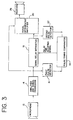
- Fig. 3 is a block diagram ofone arrangement that produces the desired result. Sound enters the microphone 12, and is converted to an electrical signal. The electrical signal is passed on to the amplifier and signal processor 14 to perform the normal functions of the hearing aid. If there is an offending digital cellular telephone handset in operation near this hearing aid, or some other similarly offending device, the RF bursts from the telephone will be rectified in the semiconductors, if the defensive measures in the hearing aid mentioned earlier are not completely effective. The RF burst will then create reoccurring pulses in the signal string being fed to a first pulse detector 16, a signal delay apparatus 18 and a signal differencing amplifier 20. After the pulse traverses the signal delay apparatus 18, it will be again be recognized by a second pulse detector 22.
- a pulse timing comparator 24 applies a correction to the signal delay apparatus 18 to make the delay for the next pair of pulses coincident.
- the two consecutive pulses arrive simultaneously at the signal differencing amplifier 20, being equal or very nearly equal, they cancel the first pulse as a component of the signal to the receiver.
- the signal unless it is repeating at the same rate as the pulses, will be different and is not canceled. Some information is lost, but enough is retained to leave an improved signal at the output 26 of the hearing aid.
- the filter would be located within the hearing aid, potentially within the receiver itself.
- the filter is shown in block diagram form in Figure 3, those skilled in the art will readily realize that the present invention can be implemented as a program for controlling the operation of a digital signal processor within a hearing aid.
- the device 110 includes two delay lines to increase bandwidth and provide a mid-point tap.
- the input of the first delay line 112 is operably coupled to a microphone 114 and the inverting inputs of a first amplifier 116 and a second amplifier 118 having preferred gains ofabout 1 and .8125, respectively.
- the output of the first delay line 112 is operably coupled to the input of the second delay line 120 and the non-inverting input of the first amplifier 116.
- the output of the second delay line 120 is operably coupled to the non-inverting input of the second amplifier 118 and a pull-down resistor 122 tied to ground with a resistance of about 100 ohms. Coupled between the outputs of the amplifiers 116,118 are a pair of serially connected resistors 124,126 having individual resistance values of about 1000 ohms each. As shown in Figure 5, the frequency response of the various outputs of the device 110 are depicted wherein the RF interference is substantially mitigated at the output 128 between the serially connected resistors 124,126.
- FIG. 6 a simplified schematic diagram is depicted of another embodiment of a filter device 210 for mitigating RF interference that uses only one delay line 220.
- a pair of serially connected resistors 224,226 are coupled between a microphone 214 and the output of a second amplifier 218.
- the resistors 224 and 226 preferably have resistance values of about 1000 and 1500 ohms, respectively.
- the output of the first amplifier 216 is attached to the input of the delay line 220 and the inverting input of the second amplifier 218.
- the output of the delay line 220 is coupled to the non-inverting input ofthe second amplifier 218 and a pull down resistor 222 tied to ground.
- the second amplifier 218 has a gain of about 10 and the resistor 222 has a resistance value of about 100 ohms.
- the first amplifier 216 drives the filter wherein the output 228 of the filter is summed with the input signal from the microphone 214 by an amount determined by the resistance values of resistors 224 and 226. Accordingly, the signal arriving from the output 228 and through resistor 226 is similar to a negative feedback amplifier for producing flat responses. Thus, device 210 flattens the response by increasing the transmission near the comb frequencies, but the notch frequencies cannot reach the output terminal 228.
- Figures 7 and 8 The result of the filtering by device 210 is depicted in Figures 7 and 8 wherein, for convenience, the device is set to 200 Hz rather than the desired frequency of 217Hz.
- Figure 7 depicts the frequency response of the device 210 at output 228.
- Figure 8 provides a phase plot ofthe device 210.
Landscapes
- Health & Medical Sciences (AREA)
- General Health & Medical Sciences (AREA)
- Neurosurgery (AREA)
- Otolaryngology (AREA)
- Physics & Mathematics (AREA)
- Engineering & Computer Science (AREA)
- Acoustics & Sound (AREA)
- Signal Processing (AREA)
- Noise Elimination (AREA)
- Networks Using Active Elements (AREA)
Applications Claiming Priority (4)
| Application Number | Priority Date | Filing Date | Title |
|---|---|---|---|
| US7657198P | 1998-03-02 | 1998-03-02 | |
| US76571P | 1998-03-02 | ||
| US09/258,628 US6307944B1 (en) | 1998-03-02 | 1999-02-26 | System for mitigating RF interference in a hearing aid |
| US258628 | 1999-02-26 |
Publications (2)
| Publication Number | Publication Date |
|---|---|
| EP0941015A2 true EP0941015A2 (de) | 1999-09-08 |
| EP0941015A3 EP0941015A3 (de) | 2001-01-03 |
Family
ID=26758247
Family Applications (1)
| Application Number | Title | Priority Date | Filing Date |
|---|---|---|---|
| EP99301500A Withdrawn EP0941015A3 (de) | 1998-03-02 | 1999-03-01 | System zur RF-Interferenzreduzierung in einem Hörhilfegerät |
Country Status (2)
| Country | Link |
|---|---|
| US (1) | US6307944B1 (de) |
| EP (1) | EP0941015A3 (de) |
Cited By (2)
| Publication number | Priority date | Publication date | Assignee | Title |
|---|---|---|---|---|
| EP1501200A3 (de) * | 2004-11-12 | 2005-03-16 | Phonak Ag | Störsignalfilter in Hörgeräten |
| US7529378B2 (en) | 2004-11-12 | 2009-05-05 | Phonak Ag | Filter for interfering signals in hearing devices |
Families Citing this family (16)
| Publication number | Priority date | Publication date | Assignee | Title |
|---|---|---|---|---|
| US7072482B2 (en) | 2002-09-06 | 2006-07-04 | Sonion Nederland B.V. | Microphone with improved sound inlet port |
| US7363063B2 (en) * | 2004-08-31 | 2008-04-22 | Research In Motion Limited | Mobile wireless communications device with reduced interference from the keyboard into the radio receiver |
| US7398072B2 (en) | 2004-08-31 | 2008-07-08 | Research In Motion Limited | Mobile wireless communications device with reduced microphone noise from radio frequency communications circuitry |
| US7243851B2 (en) * | 2004-08-31 | 2007-07-17 | Research In Motion Limited | Mobile wireless communications device with reduced interfering energy from the keyboard |
| US7328047B2 (en) | 2004-08-31 | 2008-02-05 | Research In Motion Limited | Mobile wireless communications device with reduced interfering energy from the display and related methods |
| US7444174B2 (en) | 2004-08-31 | 2008-10-28 | Research In Motion Limited | Mobile wireless communications device with reduced interfering energy into audio circuit and related methods |
| US7353041B2 (en) * | 2005-04-04 | 2008-04-01 | Reseach In Motion Limited | Mobile wireless communications device having improved RF immunity of audio transducers to electromagnetic interference (EMI) |
| US7616973B2 (en) | 2006-01-30 | 2009-11-10 | Research In Motion Limited | Portable audio device having reduced sensitivity to RF interference and related methods |
| US8099064B2 (en) * | 2008-05-08 | 2012-01-17 | Research In Motion Limited | Mobile wireless communications device with reduced harmonics resulting from metal shield coupling |
| US9590571B2 (en) | 2012-10-02 | 2017-03-07 | Knowles Electronics, Llc | Single stage buffer with filter |
| US9402131B2 (en) | 2013-10-30 | 2016-07-26 | Knowles Electronics, Llc | Push-pull microphone buffer |
| US9485594B2 (en) | 2014-08-06 | 2016-11-01 | Knowles Electronics, Llc | Connector arrangement in hearing instruments |
| US9859879B2 (en) | 2015-09-11 | 2018-01-02 | Knowles Electronics, Llc | Method and apparatus to clip incoming signals in opposing directions when in an off state |
| US10542354B2 (en) * | 2017-06-23 | 2020-01-21 | Gn Hearing A/S | Hearing device with suppression of comb filtering effect |
| US11115744B2 (en) | 2018-04-02 | 2021-09-07 | Knowles Electronics, Llc | Audio device with conduit connector |
| CN213818100U (zh) | 2019-12-30 | 2021-07-27 | 楼氏电子(苏州)有限公司 | 麦克风组件 |
Family Cites Families (5)
| Publication number | Priority date | Publication date | Assignee | Title |
|---|---|---|---|---|
| US3794766A (en) * | 1973-02-08 | 1974-02-26 | Bell Telephone Labor Inc | Delay equalizing circuit for an audio system using multiple microphones |
| DE19545760C1 (de) | 1995-12-07 | 1997-02-20 | Siemens Audiologische Technik | Digitales Hörgerät |
| DE19547195A1 (de) | 1995-12-16 | 1997-06-19 | Hoermann Audifon Gmbh | Miniaturisiertes, im oder am Ohr zu tragendes Hörgerät |
| US5768397A (en) | 1996-08-22 | 1998-06-16 | Siemens Hearing Instruments, Inc. | Hearing aid and system for use with cellular telephones |
| US6097823A (en) * | 1996-12-17 | 2000-08-01 | Texas Instruments Incorporated | Digital hearing aid and method for feedback path modeling |
-
1999
- 1999-02-26 US US09/258,628 patent/US6307944B1/en not_active Expired - Fee Related
- 1999-03-01 EP EP99301500A patent/EP0941015A3/de not_active Withdrawn
Cited By (2)
| Publication number | Priority date | Publication date | Assignee | Title |
|---|---|---|---|---|
| EP1501200A3 (de) * | 2004-11-12 | 2005-03-16 | Phonak Ag | Störsignalfilter in Hörgeräten |
| US7529378B2 (en) | 2004-11-12 | 2009-05-05 | Phonak Ag | Filter for interfering signals in hearing devices |
Also Published As
| Publication number | Publication date |
|---|---|
| EP0941015A3 (de) | 2001-01-03 |
| US6307944B1 (en) | 2001-10-23 |
Similar Documents
| Publication | Publication Date | Title |
|---|---|---|
| US6307944B1 (en) | System for mitigating RF interference in a hearing aid | |
| US3586781A (en) | Telecommunication apparatus | |
| EP0578604B1 (de) | Signalkomprimiersystem für Audiofrequenzen | |
| JP4446125B2 (ja) | 1個のトランスデューサを有する双方向通信装置及びその方法 | |
| US5563952A (en) | Automatic dynamic VOX circuit | |
| US4560840A (en) | Digital handsfree telephone | |
| US4433435A (en) | Arrangement for reducing the noise in a speech signal mixed with noise | |
| EP1111960B1 (de) | Digitales Hörhilfegerät und Verfahren | |
| DE3887786T2 (de) | Elektronisches Fernmeldegerät mit Rauschunterdrückungsfunktion. | |
| EP0692903A1 (de) | Freisprechanlage mit Echokompensator | |
| US11468873B2 (en) | Gradual reset of filter coefficients in an adaptive noise cancellation system | |
| US7003096B2 (en) | Full duplex telephone set using echo cancellation and side tone management for high gain stability | |
| CA2100015A1 (en) | Auditory prosthesis with user-controlled feedback cancellation | |
| US5533119A (en) | Method and apparatus for sidetone optimization | |
| US20140257799A1 (en) | Shout mitigating communication device | |
| EP0185815A1 (de) | Pegelregelung für ein Fernsprechsystem mit Infrarot-Fernübertragung | |
| JP3342642B2 (ja) | 電話送受器インタフェース装置 | |
| GB2301731A (en) | Speakerphone | |
| US6360203B1 (en) | System and method for dynamic voice-discriminating noise filtering in aircraft | |
| MXPA97000906A (en) | Microtelphon interface with reality control | |
| EP0843427A1 (de) | Vorrichtung zur Unterdrückung von harmonischen Störungen bei Signalübertragungen | |
| US11875769B2 (en) | Baby monitor system with noise filtering and method thereof | |
| US4453039A (en) | Arrangement for avoiding annoying sustained oscillations in a closed-loop system and loud-speaking telephone set employing this arrangement | |
| KR100272130B1 (ko) | 전화기에서의 하울링 제거 장치 및 방법 | |
| DE3426815A1 (de) | Pegelregulierung fuer eine fernsprechstation mit freisprechen |
Legal Events
| Date | Code | Title | Description |
|---|---|---|---|
| PUAI | Public reference made under article 153(3) epc to a published international application that has entered the european phase |
Free format text: ORIGINAL CODE: 0009012 |
|
| AK | Designated contracting states |
Kind code of ref document: A2 Designated state(s): DE DK GB NL |
|
| AX | Request for extension of the european patent |
Free format text: AL;LT;LV;MK;RO;SI |
|
| RAP1 | Party data changed (applicant data changed or rights of an application transferred) |
Owner name: KNOWLES ELECTRONICS, LLC |
|
| PUAL | Search report despatched |
Free format text: ORIGINAL CODE: 0009013 |
|
| AK | Designated contracting states |
Kind code of ref document: A3 Designated state(s): AT BE CH CY DE DK ES FI FR GB GR IE IT LI LU MC NL PT SE |
|
| AX | Request for extension of the european patent |
Free format text: AL;LT;LV;MK;RO;SI |
|
| RIC1 | Information provided on ipc code assigned before grant |
Free format text: 7H 04R 25/00 A, 7H 04B 15/00 B |
|
| 17P | Request for examination filed |
Effective date: 20010425 |
|
| AKX | Designation fees paid |
Free format text: DE DK GB NL |
|
| 17Q | First examination report despatched |
Effective date: 20031212 |
|
| STAA | Information on the status of an ep patent application or granted ep patent |
Free format text: STATUS: THE APPLICATION IS DEEMED TO BE WITHDRAWN |
|
| 18D | Application deemed to be withdrawn |
Effective date: 20040423 |