EP0940991A2 - Verfahren und Vorrichtung zur Erzeugung vorbestimmter Teilbilder aus einem grösseren Bild mit unabhängigen Makroblöcken - Google Patents
Verfahren und Vorrichtung zur Erzeugung vorbestimmter Teilbilder aus einem grösseren Bild mit unabhängigen Makroblöcken Download PDFInfo
- Publication number
- EP0940991A2 EP0940991A2 EP99301283A EP99301283A EP0940991A2 EP 0940991 A2 EP0940991 A2 EP 0940991A2 EP 99301283 A EP99301283 A EP 99301283A EP 99301283 A EP99301283 A EP 99301283A EP 0940991 A2 EP0940991 A2 EP 0940991A2
- Authority
- EP
- European Patent Office
- Prior art keywords
- image
- selected image
- view
- image view
- larger compressed
- Prior art date
- Legal status (The legal status is an assumption and is not a legal conclusion. Google has not performed a legal analysis and makes no representation as to the accuracy of the status listed.)
- Withdrawn
Links
- 238000000034 method Methods 0.000 title claims description 53
- 238000013500 data storage Methods 0.000 claims description 7
- 238000012545 processing Methods 0.000 abstract description 5
- 230000003068 static effect Effects 0.000 abstract description 5
- 238000001514 detection method Methods 0.000 description 24
- 230000008569 process Effects 0.000 description 24
- 238000007906 compression Methods 0.000 description 6
- 230000006835 compression Effects 0.000 description 6
- 238000012360 testing method Methods 0.000 description 6
- 239000002131 composite material Substances 0.000 description 4
- 230000005540 biological transmission Effects 0.000 description 2
- 238000010586 diagram Methods 0.000 description 2
- 238000012544 monitoring process Methods 0.000 description 2
- 238000013139 quantization Methods 0.000 description 2
- 230000009467 reduction Effects 0.000 description 2
- 230000008901 benefit Effects 0.000 description 1
- 238000007796 conventional method Methods 0.000 description 1
- 238000013144 data compression Methods 0.000 description 1
- 230000006837 decompression Effects 0.000 description 1
- 238000012986 modification Methods 0.000 description 1
- 230000004048 modification Effects 0.000 description 1
- 238000004091 panning Methods 0.000 description 1
- 230000035945 sensitivity Effects 0.000 description 1
- 230000009466 transformation Effects 0.000 description 1
Images


Classifications
-
- H—ELECTRICITY
- H04—ELECTRIC COMMUNICATION TECHNIQUE
- H04N—PICTORIAL COMMUNICATION, e.g. TELEVISION
- H04N19/00—Methods or arrangements for coding, decoding, compressing or decompressing digital video signals
-
- H—ELECTRICITY
- H04—ELECTRIC COMMUNICATION TECHNIQUE
- H04N—PICTORIAL COMMUNICATION, e.g. TELEVISION
- H04N19/00—Methods or arrangements for coding, decoding, compressing or decompressing digital video signals
- H04N19/20—Methods or arrangements for coding, decoding, compressing or decompressing digital video signals using video object coding
- H04N19/23—Methods or arrangements for coding, decoding, compressing or decompressing digital video signals using video object coding with coding of regions that are present throughout a whole video segment, e.g. sprites, background or mosaic
-
- H—ELECTRICITY
- H04—ELECTRIC COMMUNICATION TECHNIQUE
- H04N—PICTORIAL COMMUNICATION, e.g. TELEVISION
- H04N19/00—Methods or arrangements for coding, decoding, compressing or decompressing digital video signals
- H04N19/60—Methods or arrangements for coding, decoding, compressing or decompressing digital video signals using transform coding
Definitions
- the present invention relates to image encoding and decoding techniques, and more particularly, to a method and apparatus for generating a partial image from a larger compressed image (or a plurality of individual images).
- Remote cameras such as those used for security applications, traffic monitoring or daycare monitoring, are typically panned by physically moving the camera.
- the utility of such remote cameras is limited in that only one user can control the camera at a time.
- a number of software techniques have been developed for permitting a number of users to view selected portions of a larger image (or a composite image generated from a plurality of individual images).
- Permitting multiple selected views of a larger image becomes more difficult if the larger image is compressed. Specifically, since image data following image compression is of variable length, pixel boundaries are not readily detectable in a compressed image. In addition, since many encoding techniques exhibit intra-frame pixel dependencies, such as encoding the difference values for adjacent DC coefficients under the JPEG standard, the pixel values must be modified when generating a selected portion of a larger image, to reflect the reordering of the subset of pixels in the selected image view.
- the larger image when generating a selected portion of a larger compressed image, the larger image must be decompressed into the pixel domain, before the pixel values are reordered and assembled to create each of the selected image views. Thereafter, each of the selected image views is compressed to form the final images transmitted to each user.
- the more popular image compression techniques such as JPEG and MPEG, typically perform three steps to generate a compressed image, namely, (i) transformation, such as a discrete cosine transform (DCT); (ii) quantization; and (iii) run-length encoding (RLE).
- the inverse of the compression steps are performed by the receiver on the compressed image, namely, (i) run-length decode; (ii) dequantization; and (iii) inverse discrete cosine transform (IDCT).
- a selected image view generator for generating a selected portion of a larger compressed image.
- the larger compressed image includes a plurality of macroblocks of image data, encoded using an intraframe encoding technique.
- the macroblocks do not need to be encoded independently.
- a portion of the DC coefficient values are recomputed when generating the selected image view from the overall image, to reflect the reordering of the pixels in the selected image view (that results in a portion of the pixels being adjacent to different pixels than they were in a subimage).
- a selected image view is generated from a larger compressed image having a plurality of macroblocks of image data
- Each of the macroblocks contains one or more blocks of data, with each block having a DC coefficient value.
- the blocks from the larger compressed image that are included in the selected image view are identified, and then the DC coefficient values are recomputed for each block in the selected image view that is encoded relative to a different block than it was encoded relative to in the larger compressed image. Finally, the identified blocks are assembled to form the selected image view.
- multiple users can simultaneously control a selected view received from an image source.
- Remote cameras can be panned electronically, rather than physically.
- the overall image may include one or more static or real-time images.
- the selected image from a larger overall image may be used, for example, with a 360° panning camera, to permit each user to select a desired real-time or static view. For example, for a tennis match, different users can watch different players from the same video feed.
- FIG. 1A shows an illustrative network environment 100 for transferring multimedia information, such as image, video, voice or data information, or a combination of the foregoing, between one or more sources and destinations, such as end users 110-113 and an image source 130.
- each end user 110-113 such as end user 110
- the compressed image 160 is generated by one or more image sources, such as image source 130, and may include one or more subimages, such as subimages 160a-160d. It is noted that each subimage 160a-160d may be a full independent image.
- the image source 130 may be embodied, for example, as a 360° camera that produces panoramic images, or one or more cameras generating images that may be combined into a composite image.
- a 360° camera that produces panoramic images, or one or more cameras generating images that may be combined into a composite image.
- United States Patent Application Serial Number 08/433,356 entitled “Panoramic Viewing Apparatus,” assigned to the assignee of the present invention and incorporated by reference herein.
- a selected image view generator 200 generates the selected portion(s) 150 of the image 160, shown in FIG 1B
- each user receives the overall image 160, as well as the currently selected image view 150.
- the transmitted overall image 160 provides the user 110 with an orientation and permits the user 110 to select the desired view 150.
- the overall image 160 can be transmitted at a rate below the standard frame rate, and the currently selected image view 150 can be transmitted at the highest rate permitted by the available bandwidth.
- the user selects a viewpoint, and whatever passes in the selected viewpoint over time is presented to the user.
- the smaller selected image view 150 can be presented with a higher resolution than the overall image 160 and/or mapped to a larger portion of the display screen.
- the selected image view generator 200 may utilize a variety of image inputs, for example, received from a file server, a video-on-demand system or a real-time camera.
- the network environment 100 may be embodied, for example, as the Public Switched Telephone Network ("PSTN"), the Internet, or other broadband networks, as would be apparent to a person of ordinary skill.
- PSTN Public Switched Telephone Network
- the end users 110-113 can utilize work stations (not shown), or other general-purpose computing devices.
- a selected image view 150 from an overall image 160 is generated with significantly reduced computation and reduced latency (for video processing), permitting viewing of live events without noticeable delay.
- the present invention permits selected image views 150 to be formed from static images or from a video stream or from a combination of the foregoing.
- multiple users can simultaneously control a selected view received from the image source 130. In this manner, a user 110 obtains personalized access to the image source 130.
- each image 160 is encoded using a suitable intra-frame macroblock-based image encoder, such as a JPEG image encoder or an MPEG intra-frame image encoder
- a suitable intra-frame macroblock-based image encoder such as a JPEG image encoder or an MPEG intra-frame image encoder
- each image 160 consists of macroblocks of pixels.
- Macroblocks are typically a 16 x 8 or a 16 x 16 pixel array.
- macroblocks are transmitted sequentially from left to right, top to bottom.
- 2400 16 ⁇ 8 macroblocks would constitute an entire 640 x 480 pixel frame.
- the macroblocks constitute one or more independent color components, which may be at different resolution levels.
- each illustrative 16 x 8 macroblock is represented by 2 luminance (Y) blocks and 2 chrominance (C b ,C r ) blocks, with each block containing 1 DC coefficient value, and 63 AC coefficient values.
- many intra-frame encoding techniques including JPEG and MPEG, encode the difference values for adjacent DC coefficients, as opposed to the absolute DC value.
- a portion of the DC coefficient values are recomputed when generating the selected image view 150 from the overall image 160, to reflect the reordering of the pixels in the selected image view resulting in a portion of the pixels being adjacent to different pixels (than they were in the respective subimage 160a-160d).
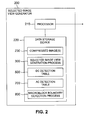
- FIG. 2 is a block diagram showing the architecture of an illustrative selected image view generator 200.
- the selected image view generator 200 preferably includes a processor 210 and related memory, such as a data storage device 220.
- the processor 210 may be embodied as a single processor, or a number of processors operating in parallel.
- the data storage device 220 or another memory is operable to store one or more instructions, which the processor 210 is operable to retrieve, interpret and execute.
- the data storage device 220 preferably includes an area of memory 230 for storing the compressed image(s) 160.
- the selected image view generator 200 may receive the compressed image(s) 160 from the image source 130 for processing in real-time or static compressed images may be retrieved from a database of images, such as a video server, as would be apparent to a person of ordinary skill.
- the data storage device 220 preferably includes a selected image view generation process 300.
- the selected image view generation process 300 retrieves the encoded input image data; (ii) retrieves an indication of the image view selected by the user; and (iii) generates and transmits the selected image view 150 to the user.
- the data storage device 220 may also include a DC detection table 500 and an AC detection table 700.
- the DC detection table 500 and AC detection table 700 preferably store detection information for each codeword.
- the data storage device 220 preferably includes a macroblock boundary detection process 800.
- the macroblock boundary detection process 800 evaluates the input image data and decodes the data only enough to identify where each macroblock ends.
- the selected image view generation process 300 initially retrieves the overall image 160 during step 310.
- the selected image view generation process 300 identifies the macroblock at the left edge of the first row of the selected image view 150 during step 320.
- a new restart interval (JPEG) or slice (MPEG) is inserted at the beginning of each row in the selected image view 150.
- JPEG JPEG
- MPEG slice
- a restart header is preferably inserted at the left edge of the current row of the first subimage 160a-160d in the selected image view 150 during step 325.
- the restart/slice header includes the vertical and horizontal position (or address) of the first macroblock in the slice.
- the selected image view generation process 300 goes to the closest previous DC coefficient that has been decoded, or to the beginning of the current slice for MPEG images or restart interval for JPEG images, which could be external to the selected image view 150, whichever is closer. In other words, the selected image view generation process 300 returns to the preceding closest macroblock during step 330 having a known absolute DC value. For the first pass through the selected image view generation process 300, however, when the first row of the selected image view 150 is being processed, no DC coefficients have been decoded and stored by the selected image view generation process 300. Thus, the selected image view generation process 300 will go to the beginning of the slice/restart interval containing the first macroblock in the selected image view 150.
- the DC coefficients up to the left edge of the current row of the current subimage 160a-d in the selected image view 150 are then decoded during step 340.
- the absolute DC coefficient values are stored as they are decoded for each subimage, so that the DC coefficient of the right. most macroblock in one row can be used during step 330 (on the subsequent pass of the selected image view generation process 300) for the subsequent row.
- the selected image view generation process 300 preferably executes a macroblock boundary detection process 800 (FIGS. 8A and 8B) during step 360.
- a macroblock boundary detection process 800 will process the image data in a given row of the selected image view 150 up to the end of the current subimage.
- a test is then performed during step 375 to determine if there is another subimage 160a-160d in the current row. If it is determined during step 375 that there is another subimage 160a-160d in the current row, then a further test is performed during step 380 to determine if the next subimage 160a-160d has a restart interval at the left edge of the current row. It is noted that the test performed during step 380 addresses the requirement in a JPEG implementation that each restart interval includes the same number of macroblocks, by ensuring that the size of each restart interval is equal to the length of each row in the selected image view 150. It may be desirable in an MPEG implementation to include multiple restart/slice intervals in each row, by placing a new restart/slice interval at the beginning of each row of each individual subimage in the selected image view 150.
- step 380 If it is determined during step 380 that the next subimage 160a-160d does not have a restart interval at the left edge of the current row, then program control returns to step 330 (FIG. 3A) and continues processing the image data in the manner described above. If, however, it is determined during step 380 that the next subimage 160a-160d does have a restart interval at the left edge of the current row, then the restart interval is removed during step 382 before program control returns to step 360, in the manner described above.
- step 375 If, however, it is determined during step 375 that there is not another subimage 160a-160d in the current row, then a further test is performed during step 385 to determine if there is another row in the selected image view 150 to be processed. If it is determined during step 385 that there is another row in the selected image view 150 to be processed, then program control returns to step 325 (FIG. 3A) to process the next row, in the manner described above.
- step 385 If, however, it is determined during step 385 that there is not another row in the selected image view 150 to be processed, then the selected image view 150 is transmitted to the user during step 390 with a modified frame header indicating the number of macroblocks in the selected image view 150, before program control terminates during step 395.
- the AC and DC coefficients are coded in a different manner.
- the DC coefficient is a multiple of the average value in the 8 x 8 block. Since the average pixel value in any 8 x 8 block will not differ substantially from the average value in a neighboring block, the DC coefficient values will typically not vary significantly. Thus, in order to achieve further bit rate reductions in the JPEG standard, the differences between adjoining coefficients are typically encoded rather than the coefficients themselves.
- the possible values that the encoded DC difference values can take in the JPEG standard are partitioned into categories, shown in FIG. 4.
- the number of elements within each category grows by a power of two. For example, category 0 has only one member, category 1 has two members and category 2 has four members.
- the category numbers are then Huffman coded.
- the particular element within each category is specified by adding additional bits to the end of the Huffman code for a given category. Since category 1 has two members, it can be differentiated using one additional bit.
- category n has 2 n members and can be differentiated using n additional bits.
- category 3 has eight values ⁇ -7, -6, -5, -4, 4, 5, 6, 7 ⁇ .
- the Huffman code for category 3 is transmitted, as well as three bits to differentiate which of the eight values in category 3 was transmitted.
- a DC decode table 500 shown in FIG. 5, is typically accessed.
- data is read in eight bit chunks, and the DC detection information provided in FIG. 5 indicates the number of additional bits to read to derive the particular element within the identified category. In this manner, the DC difference value is obtained.
- the DC difference values of each block in each individual compressed image are decoded using the decode table 500 before generating the multi-image composite, so that the DC difference values at the border of each individual image may be recalculated to reflect the reordering of the pixels, in the manner described above.
- the JPEG standard achieves significant further bit rate reductions by implementing run-length encoding on the AC coefficients.
- the number of non-zero AC coefficients since the last non-zero coefficient is also encoded. As shown in FIG. 6, the category of the non-zero coefficient to be encoded, and the "run", or the number of zero coefficients preceding the current non-zero coefficient, form a pointer to a specific Huffman code.
- category n has 2 n members and can be differentiated using n additional bits
- the category number indicates the number of additional bits.
- the Huffman code for a coefficient in category n is followed by n additional bits.
- the encoded information is therefore the to consist of a run/length, where the run is the number of coefficients having a zero value preceding the current non-zero coefficient, and the length is the number of additional bits to differentiate the particular member within a given category.
- the AC coefficients are only decoded enough to permit counting of the coefficients until 63 AC coefficients have been processed, or an end-of-block code has been detected.
- the AC coefficients are variable-length decoded and run length decoded.
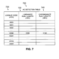
- an AC detection table 700 shown in FIG. 7, is utilized which returns detection information for each codeword.
- the AC detection table 700 preferably maintains separate columns for each.
- the AC detection table 700 is derived from the AC encoding table 600, shown in FIG. 6, and translates each codeword in the input image into the number of coefficients encoded (the current coefficient plus preceding zero coefficients) and the total number of bits (number of bits in the codeword, plus the number of additional bits).
- 16-bit codes are utilized as an index into the AC detection table 700.
- Each row consists of two (2) bytes of luminance detection information and two (2) bytes of chrominance detection information, in a hexadecimal notation.
- the upper byte of each two (2) bytes of detection information indicates the number of coefficients encoded (the current coefficient plus preceding zero coefficients) and the lower byte indicates the total number of bits (number of bits in the codeword, plus the number of additional bits)
- the number of coefficients encoded is utilized to increment a counter, until the total block of 63 AC coefficients has been processed (or an end of block is detected). The total numbers of bit is utilized to shift the bits to the next codeword in the stream.
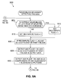
- the composite image generator 200 preferably executes a macroblock boundary detection process 800, shown in FIGS. 8A and 8B, to evaluate the input image data and decode the data only enough to identify where each macroblock ends.
- the macroblock boundary detection process 800 is executed by the selected image view generation process 300 for each subimage in each row of the selected image view 150.
- the macroblock boundary detection process 800 initially performs a test during step 805 to determine if the current macroblock is at the left edge of the selected image view 150 or the left edge of a subimage 160a-160d.
- a restart interval is preferably inserted only at the beginning of each row in the selected image view 150, and any additional restart intervals in a given row are removed by the selected image view generation process 300, discussed above.
- the DC coefficients of the macroblocks at the left edge of the selected image view 150 (following the new restart intervals) will have to be recomputed to provide their absolute value, as opposed to their differential value relative to the previous DC coefficient in the subimage.
- the DC coefficients of the macroblocks at the left edge of additional subimages (other than the first subimage) in the selected image view 150 will have to be recomputed as well.
- the DC coefficients of the macroblocks at the left edge of the respective additional subimage are recomputed to provide their differential value relative to the previous DC coefficient in the previous subimage, as opposed to the absolute value that was provided with the removed restart interval. If a restart interval was not removed from an additional subimage, the DC coefficients of the macroblocks at the left edge of the respective additional subimage are recomputed to provide their new differential value relative to the previous DC coefficient in the previous subimage.
- step 805 If it is determined during step 805 that the current macroblock is at the left edge of the selected image view 150 or the left edge of a subimage 160a-160d, then a recompute flag is set to one during step 810, so that the appropriate DC coefficients in the macroblock can be recomputed. If, however, it is determined during step 805 that the current macroblock is not at the left edge of the selected image view 150 or the left edge of a subimage 160a-160d, then a recompute flag is set to zero during step 815, so that the DC coefficients in the macroblock are not recomputed.
- the DC coefficient in the first Y block is recomputed during step 820, if the recompute flag has a value of one.
- the DC coefficient and 63 AC coefficients associated with the first Y block are then detected and placed in the output data during step 825. It is noted that the recomputed DC values will cause bit shifting in the data, so when the coefficients are placed in the output data the bits must be shifted and it is not a simple copy.
- the DC coefficient in the first Cb block is recomputed during step 840 (FIG. 8B), if the recompute flag has a value of one.
- the DC coefficient and 63 AC coefficients associated with the first Cb block are then detected and placed in the output data during step 845.
- the DC coefficient for subsequent Cb, if any, blocks are not recomputed, and the DC coefficient and 63 AC coefficients of subsequent Cb blocks, if any, are detected and placed in the output data during step 848.
- the DC coefficient in the first Cr block is recomputed during step 850, if the recompute flag has a value of one.
- the DC coefficient and 63 AC coefficients associated with the first Cr block are then detected and placed in the output data during step 852.
- the DC coefficient for subsequent Cr blocks, if any, are not recomputed, and the DC coefficient and 63 AC coefficients of subsequent Cr blocks, if any, are detected and placed in the output data during step 855.
- a test is then performed during step 860 to determine if the end of the current row of the selected image view 150 or the end of the current subimage 160a-160d has been reached. If it is determined during step 860 that the end of the current row of the selected image view 150 or the end of the current subimage 160a-160d has not been reached, then the next macroblock in the selected image view 150 is obtained during step 870 before program control returns to step 805 for processing of the next macroblock in the manner described above.
- step 860 If, however, it is determined during step 860 that the end of the current row of the selected image view 150 or the end of the current subimage 160a-160d has been reached, then program control terminates during step 880.
Landscapes
- Engineering & Computer Science (AREA)
- Multimedia (AREA)
- Signal Processing (AREA)
- Compression Or Coding Systems Of Tv Signals (AREA)
- Closed-Circuit Television Systems (AREA)
- Compression, Expansion, Code Conversion, And Decoders (AREA)
Applications Claiming Priority (2)
| Application Number | Priority Date | Filing Date | Title |
|---|---|---|---|
| US09/036,141 US6246801B1 (en) | 1998-03-06 | 1998-03-06 | Method and apparatus for generating selected image views from a larger image having dependent macroblocks |
| US36141 | 1998-03-06 |
Publications (2)
| Publication Number | Publication Date |
|---|---|
| EP0940991A2 true EP0940991A2 (de) | 1999-09-08 |
| EP0940991A3 EP0940991A3 (de) | 2003-08-13 |
Family
ID=21886889
Family Applications (1)
| Application Number | Title | Priority Date | Filing Date |
|---|---|---|---|
| EP99301283A Withdrawn EP0940991A3 (de) | 1998-03-06 | 1999-02-23 | Verfahren und Vorrichtung zur Erzeugung vorbestimmter Teilbilder aus einem grösseren Bild mit unabhängigen Makroblöcken |
Country Status (3)
| Country | Link |
|---|---|
| US (1) | US6246801B1 (de) |
| EP (1) | EP0940991A3 (de) |
| JP (1) | JP2000032460A (de) |
Families Citing this family (8)
| Publication number | Priority date | Publication date | Assignee | Title |
|---|---|---|---|---|
| US6941019B1 (en) * | 2000-05-10 | 2005-09-06 | International Business Machines Corporation | Reentry into compressed data |
| US7146053B1 (en) | 2000-05-10 | 2006-12-05 | International Business Machines Corporation | Reordering of compressed data |
| JP3924420B2 (ja) | 2000-07-11 | 2007-06-06 | Necエレクトロニクス株式会社 | 画像圧縮装置及びその方法 |
| KR20020032862A (ko) * | 2000-10-27 | 2002-05-04 | 신재섭 | 동영상 부호화를 이용한 객체기반 멀티미디어 서비스시스템 및 서비스 방법 |
| JP4148671B2 (ja) * | 2001-11-06 | 2008-09-10 | ソニー株式会社 | 表示画像制御処理装置、動画像情報送受信システム、および表示画像制御処理方法、動画像情報送受信方法、並びにコンピュータ・プログラム |
| US7136961B2 (en) * | 2002-11-13 | 2006-11-14 | Mosaid Technologies, Inc. | Method and apparatus for wide word deletion in content addressable memories |
| US20060256868A1 (en) * | 2005-05-16 | 2006-11-16 | Ensequence, Inc. | Methods and systems for repositioning mpeg image content without recoding |
| SE0802657A1 (sv) * | 2008-12-23 | 2010-06-24 | Scalado Ab | Extrahering av digital information |
Family Cites Families (13)
| Publication number | Priority date | Publication date | Assignee | Title |
|---|---|---|---|---|
| US5384588A (en) * | 1991-05-13 | 1995-01-24 | Telerobotics International, Inc. | System for omindirectional image viewing at a remote location without the transmission of control signals to select viewing parameters |
| KR0132894B1 (ko) * | 1992-03-13 | 1998-10-01 | 강진구 | 영상압축부호화 및 복호화 방법과 그 장치 |
| US5262855A (en) * | 1992-03-25 | 1993-11-16 | Intel Corporation | Method and apparatus for encoding selected images at lower resolution |
| US5764373A (en) * | 1993-03-16 | 1998-06-09 | Mitsubishi Denki Kabushiki Kaisha | Image data compression-expansion circuit |
| US5442400A (en) * | 1993-04-29 | 1995-08-15 | Rca Thomson Licensing Corporation | Error concealment apparatus for MPEG-like video data |
| DE69528853T2 (de) * | 1994-01-31 | 2003-07-03 | Canon K.K., Tokio/Tokyo | System und Verfahren zum Editieren bewegter Bilder |
| US5481297A (en) * | 1994-02-25 | 1996-01-02 | At&T Corp. | Multipoint digital video communication system |
| GB9421206D0 (en) * | 1994-10-20 | 1994-12-07 | Thomson Consumer Electronics | Digital VCR MPEG- trick play processing |
| KR0144260B1 (ko) * | 1994-11-15 | 1998-07-15 | 구자홍 | 피아이피 기능의 에이치디티브이 |
| GB9510093D0 (en) * | 1995-05-18 | 1995-07-12 | Philips Electronics Uk Ltd | Interactive image manipulation |
| US5878168A (en) * | 1995-06-05 | 1999-03-02 | Sony Corporation | Method and apparatus for picture encoding and decoding |
| US5666487A (en) * | 1995-06-28 | 1997-09-09 | Bell Atlantic Network Services, Inc. | Network providing signals of different formats to a user by multplexing compressed broadband data with data of a different format into MPEG encoded data stream |
| US5623308A (en) * | 1995-07-07 | 1997-04-22 | Lucent Technologies Inc. | Multiple resolution, multi-stream video system using a single standard coder |
-
1998
- 1998-03-06 US US09/036,141 patent/US6246801B1/en not_active Expired - Lifetime
-
1999
- 1999-02-23 EP EP99301283A patent/EP0940991A3/de not_active Withdrawn
- 1999-03-08 JP JP11060039A patent/JP2000032460A/ja active Pending
Also Published As
| Publication number | Publication date |
|---|---|
| US6246801B1 (en) | 2001-06-12 |
| JP2000032460A (ja) | 2000-01-28 |
| EP0940991A3 (de) | 2003-08-13 |
Similar Documents
| Publication | Publication Date | Title |
|---|---|---|
| EP0730385B1 (de) | Gerät zur Dekomprimierung von Video-Daten | |
| CN1029067C (zh) | 视频信号压缩装置 | |
| CN1048135C (zh) | 数字变换压缩的视频数据的低分辨率解压缩设备 | |
| US5212549A (en) | Error concealment apparatus for a compressed video signal processing system | |
| KR101177663B1 (ko) | 입체적 3d-비디오 이미지 디지털 디코딩 시스템 및 방법 | |
| TW245871B (en) | Method and apparatus for efficient addressing of dram in a video decompression processor | |
| CN1039764C (zh) | 用于在数字视频处理系统中隐藏误差的装置 | |
| US6457057B1 (en) | System for displaying a plurality of pictures and apparatuses incorporating the same | |
| JP3990630B2 (ja) | ビデオ処理 | |
| US7894681B2 (en) | Sequential decoding of progressive coded JPEGS | |
| US6246801B1 (en) | Method and apparatus for generating selected image views from a larger image having dependent macroblocks | |
| US6337882B1 (en) | Method and apparatus for generating unlimited selected image views from a larger image | |
| JPH10112862A (ja) | デジタルデータ処理方法 | |
| US20020044599A1 (en) | Method and apparatus for generating selected image views from a larger image | |
| US8068681B2 (en) | Method and system for pipelined processing in an integrated embedded image and video accelerator | |
| CA2360556C (en) | Error concealment apparatus for a compressed video signal processing system | |
| KR100449200B1 (ko) | 컴퓨터 구현 방법, 트릭재생 스트림 생성 시스템 | |
| JP4212127B2 (ja) | 符号化装置、復号装置および再符号化装置ならびに符号化方法、復号方法および再符号化方法 | |
| Reed | Improvement of MPEG-2 compression by position-dependent encoding | |
| WO2020171451A1 (ko) | 센터-투-에지 점진적 영상 부호화/복호화 방법 및 장치 | |
| Ayyagari | A bitplane coding algorithm for still and video image compression | |
| Raymond | t THREE DIMENSIONAL DCT BASED VIDEO COMPRESSION | |
| JP2001103478A (ja) | 複数のディジタル符号化ビデオエレメンタリー番組を1つの単一ディジタル符号化ビデオ番組に変換符号化するための装置および方法 | |
| KR20070011341A (ko) | 입체적 3d-비디오 이미지 디지털 디코딩 시스템 및 방법 | |
| HK1151919A (en) | System and method for decoding 3d stereoscopic video images |
Legal Events
| Date | Code | Title | Description |
|---|---|---|---|
| PUAI | Public reference made under article 153(3) epc to a published international application that has entered the european phase |
Free format text: ORIGINAL CODE: 0009012 |
|
| AK | Designated contracting states |
Kind code of ref document: A2 Designated state(s): AT BE CH CY DE DK ES FI FR GB GR IE IT LI LU MC NL PT SE |
|
| AX | Request for extension of the european patent |
Free format text: AL;LT;LV;MK;RO;SI |
|
| RIC1 | Information provided on ipc code assigned before grant |
Ipc: 7G 06T 9/00 B Ipc: 7H 04N 7/50 B Ipc: 7H 04N 7/30 B Ipc: 7H 04N 7/26 A |
|
| PUAL | Search report despatched |
Free format text: ORIGINAL CODE: 0009013 |
|
| AK | Designated contracting states |
Designated state(s): AT BE CH CY DE DK ES FI FR GB GR IE IT LI LU MC NL PT SE |
|
| AX | Request for extension of the european patent |
Extension state: AL LT LV MK RO SI |
|
| AKX | Designation fees paid | ||
| REG | Reference to a national code |
Ref country code: DE Ref legal event code: 8566 |
|
| STAA | Information on the status of an ep patent application or granted ep patent |
Free format text: STATUS: THE APPLICATION IS DEEMED TO BE WITHDRAWN |
|
| 18D | Application deemed to be withdrawn |
Effective date: 20040214 |