EP0940581B1 - Pressure pulsation muffler for the discharge valve of a compressor - Google Patents
Pressure pulsation muffler for the discharge valve of a compressor Download PDFInfo
- Publication number
- EP0940581B1 EP0940581B1 EP99102894A EP99102894A EP0940581B1 EP 0940581 B1 EP0940581 B1 EP 0940581B1 EP 99102894 A EP99102894 A EP 99102894A EP 99102894 A EP99102894 A EP 99102894A EP 0940581 B1 EP0940581 B1 EP 0940581B1
- Authority
- EP
- European Patent Office
- Prior art keywords
- compressor
- chamber
- discharge
- housing
- cam plate
- Prior art date
- Legal status (The legal status is an assumption and is not a legal conclusion. Google has not performed a legal analysis and makes no representation as to the accuracy of the status listed.)
- Expired - Lifetime
Links
- 230000010349 pulsation Effects 0.000 title description 16
- 238000013016 damping Methods 0.000 claims description 24
- 238000006073 displacement reaction Methods 0.000 claims description 23
- 238000011144 upstream manufacturing Methods 0.000 claims description 15
- 230000006835 compression Effects 0.000 claims description 11
- 238000007906 compression Methods 0.000 claims description 11
- 239000003507 refrigerant Substances 0.000 description 69
- 238000010276 construction Methods 0.000 description 10
- 230000000694 effects Effects 0.000 description 10
- 239000010687 lubricating oil Substances 0.000 description 10
- 230000007423 decrease Effects 0.000 description 8
- 230000002411 adverse Effects 0.000 description 5
- 230000005534 acoustic noise Effects 0.000 description 3
- 238000001816 cooling Methods 0.000 description 3
- 230000035939 shock Effects 0.000 description 3
- 230000002159 abnormal effect Effects 0.000 description 2
- 238000013459 approach Methods 0.000 description 2
- 239000012530 fluid Substances 0.000 description 2
- 238000005461 lubrication Methods 0.000 description 2
- 230000008021 deposition Effects 0.000 description 1
- 230000005284 excitation Effects 0.000 description 1
- 230000005281 excited state Effects 0.000 description 1
- 230000001050 lubricating effect Effects 0.000 description 1
- 238000000034 method Methods 0.000 description 1
- 239000003921 oil Substances 0.000 description 1
- 230000002035 prolonged effect Effects 0.000 description 1
Images


Classifications
-
- F—MECHANICAL ENGINEERING; LIGHTING; HEATING; WEAPONS; BLASTING
- F04—POSITIVE - DISPLACEMENT MACHINES FOR LIQUIDS; PUMPS FOR LIQUIDS OR ELASTIC FLUIDS
- F04B—POSITIVE-DISPLACEMENT MACHINES FOR LIQUIDS; PUMPS
- F04B39/00—Component parts, details, or accessories, of pumps or pumping systems specially adapted for elastic fluids, not otherwise provided for in, or of interest apart from, groups F04B25/00 - F04B37/00
- F04B39/0027—Pulsation and noise damping means
- F04B39/0055—Pulsation and noise damping means with a special shape of fluid passage, e.g. bends, throttles, diameter changes, pipes
-
- F—MECHANICAL ENGINEERING; LIGHTING; HEATING; WEAPONS; BLASTING
- F04—POSITIVE - DISPLACEMENT MACHINES FOR LIQUIDS; PUMPS FOR LIQUIDS OR ELASTIC FLUIDS
- F04B—POSITIVE-DISPLACEMENT MACHINES FOR LIQUIDS; PUMPS
- F04B27/00—Multi-cylinder pumps specially adapted for elastic fluids and characterised by number or arrangement of cylinders
- F04B27/08—Multi-cylinder pumps specially adapted for elastic fluids and characterised by number or arrangement of cylinders having cylinders coaxial with, or parallel or inclined to, main shaft axis
- F04B27/10—Multi-cylinder pumps specially adapted for elastic fluids and characterised by number or arrangement of cylinders having cylinders coaxial with, or parallel or inclined to, main shaft axis having stationary cylinders
- F04B27/1036—Component parts, details, e.g. sealings, lubrication
-
- F—MECHANICAL ENGINEERING; LIGHTING; HEATING; WEAPONS; BLASTING
- F04—POSITIVE - DISPLACEMENT MACHINES FOR LIQUIDS; PUMPS FOR LIQUIDS OR ELASTIC FLUIDS
- F04B—POSITIVE-DISPLACEMENT MACHINES FOR LIQUIDS; PUMPS
- F04B49/00—Control, e.g. of pump delivery, or pump pressure of, or safety measures for, machines, pumps, or pumping installations, not otherwise provided for, or of interest apart from, groups F04B1/00 - F04B47/00
- F04B49/22—Control, e.g. of pump delivery, or pump pressure of, or safety measures for, machines, pumps, or pumping installations, not otherwise provided for, or of interest apart from, groups F04B1/00 - F04B47/00 by means of valves
- F04B49/225—Control, e.g. of pump delivery, or pump pressure of, or safety measures for, machines, pumps, or pumping installations, not otherwise provided for, or of interest apart from, groups F04B1/00 - F04B47/00 by means of valves with throttling valves or valves varying the pump inlet opening or the outlet opening
Definitions
- the present invention relates generally to compressors and, more particularly, relates to compressors provided with a discharge muffler in a discharge passage.
- a compressor comprising a discharge chamber and an attenuator adjusting the restriction to fluid flow through the discharge chamber.
- the attenuator includes a first orifice which may be opened and closed by a movable valve member. Further, the attenuator includes a plurality of passages forming a second orifice and providing a fluid bypass around the valve member. This has the effect of providing an uninterrupted flow passage through the discharge chamber even when the valve member is sealingly engaged over the first orifice.
- the compressor is provided with a discharge passage for the compressed gas discharged from a discharge valve.
- a discharge muffler is arranged in the discharge passage and a check valve is located downstream of the discharge muffler.
- the discharge passage is blocked by the check valve when the compressor is not in operation.
- a conventional compressor employing the aforementioned arrangement would still produce discharge gas pressure pulsation when a valve element of its check valve begins to hunt, and such pressure pulsations are likely to cause the external refrigerant circuit to generate vibrations and acoustic noise. This is mainly because the check valve is provided downstream of the discharge muffler in the discharge passage.
- Another problem of the conventional arrangement in which the check valve is provided downstream of the discharge muffler is that during stopping of the operation of the compressor, the high-pressure discharge gas, an amount of which is as much as the volumetric capacity of the discharge muffler, flows back into a crankcase of the compressor. This results in an excessive increase in the internal pressure of the crankcase and produces an adverse effect on the durability of a lip-type seal mounted on a rotary shaft of the compressor.
- a compressor comprising a discharge passage for the compressed gas discharged from a discharge valve of the compressor, wherein an open/close device is disposed in the discharge passage on a downstream side of said discharge valve for preventing the compressed gas from flowing back into the compressor and wherein a damping chamber is formed in the discharge passage on a downstream side of the open/close device.
- the open/close device is provided upstream of the discharge muffler, and the open/close device opens and closes in accordance with a pressure difference between the upstream side and the downstream side of the open/close device. If pressure pulsations occur, due to hunting of a valve element of the open/close device, during opening/closing operation of the open/close device, then such pressure pulsations are suppressed by the discharge muffler. Further, since the open/close device is provided upstream of the discharge muffler, high-pressure discharge gas in the discharge passage on the downstream side of the open/close device as well as the volumetric capacity of the discharge muffler will not flow back into the compressor when it is not in operation.
- the aforementioned compressor is a variable displacement compressor.
- the variable displacement compressor has a cylinder bore and a crankcase that are formed in a housing.
- a piston is fitted in the cylinder bore, and a cam plate is provided in the crankcase.
- the displacement capacity of the compressor is varied by controlling the angle of inclination of the cam plate in accordance with the difference between the internal pressure of the crankcase and a suction pressure present on both sides of the piston.
- the compressor further comprises a pressure-release channel interconnecting the crankcase and a suction pressure region, a pressure supply channel interconnecting a discharge chamber and the crankcase, and a capacity control valve for opening and closing the pressure supply channel.
- the capacity control valve opens the pressure supply channel when the compressor is stopped.
- the capacity control valve is opened when the compressor has been stopped in this construction, the refrigerant gas in the discharge chamber is supplied to the crankcase through the pressure supply channel, causing an increase in the internal pressure of the crankcase.
- the refrigerant gas in the crankcase is admitted into the suction pressure region through the pressure-release channel.
- the high-pressure discharge gas an amount of which is as much as the volumetric capacity of the discharge muffler, would not be supplied back to the crankcase because the open/close device is provided upstream of the discharge muffler. This makes it possible to limit the amount of the lubricating oil flowing out of the crankcase through the pressure-release channel to minimal level.
- the aforementioned housing is constructed of a front housing block in which the crankcase swingably accommodating the cam plate is formed, a cylinder block which is connected to the front housing block and accommodates a single-ended piston which moves back and forth as a result of a rotary motion of the cam plate, and a rear housing block which is connected to the cylinder block.
- the aforementioned discharge muffler is preferably formed bridging a joint between the cylinder block and the front housing block.
- the aforementioned open/close device is provided in the discharge passage which is formed in the rear housing block.
- the discharge passage formed in the rear housing block includes an accommodating compartment which is formed between and opens to a joint surface of the rear housing block facing the cylinder block.
- the aforementioned open/close device is fitted in the accommodating compartment.
- the open/close device can be easily installed in the accommodating compartment from the joint surface of the rear housing block.
- the aforementioned open/close device is a check valve.
- the aforementioned open/close device is a check valve comprising a valve element which is shifted between a position where it blocks the discharge passage and a position where it opens the discharge passage, and a spring which forces the valve element toward the position where it blocks the discharge passage.
- the discharge passage opens when the pressure on the upstream side of the check valve exceeds the sum of the pressure on the downstream side of the check valve and the elastic side of the spring, whereas the discharge passage is closed when the pressure on the upstream side of the check valve becomes lower than the sum of the pressure on the downstream side of the check valve and the elastic side of the spring.
- a front housing block 12 is joined to a front end of a cylinder block 11, and a rear housing block 13 is firmly joined to the a rear end of the cylinder block 11 with a valve plate 14, valve-forming plates 15, 16 and a retainer-forming plate 17 placed between.
- the front housing block 12, the cylinder block 11, and the rear housing block 13 thus assembled together form a housing of the compressor.
- a rotary shaft (a drive shaft) 18 is rotatably supported between the front housing block 12, in which a crankcase 121 is formed, and the cylinder block 11.
- a front end portion of the rotary shaft 18 protrudes outward from the crankcase 121 and a pulley 19 is firmly mounted on the front end portion of the rotary shaft 18.
- the pulley 19 is connected to a vehicle engine “E” by a belt 20 and is supported by the front housing block 12 by way of an angular bearing 21.
- the front housing block 12 sustains loads exerted on the pulley 19 both in its axial (thrust) and radial directions via the angular bearing 21.
- the lip-type seal 18a serves to prevent pressure leakage from the crankcase 121.
- a rotary support 22 is firmly fitted on the rotary shaft 18.
- the rotary shaft 18 also supports a cam plate 23 allowing the cam plate 23 to slide along the rotary shaft 18 and be inclined in an axial direction of the rotary shaft 18.
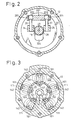
- a pair of connecting parts 24, 25 are affixed to the cam plate 23 and guide pins 26, 27 are firmly fitted in the respective connecting parts 24, 25 as shown in Figs. 2 and 4.
- Guide spheres 261, 271 are formed at extreme ends of the guide pins 26, 27, respectively.
- the rotary support 22 is provided with a projecting supporting arm 221, and a pair of guide holes 222, 223 are formed in the supporting arm 221.
- the guide spheres 261, 271 of the guide pins 26, 27 are slidably fitted in the guide holes 222, 223, respectively.
- the cam plate 23 can be inclined in the axial direction of the rotary shaft 18 and can rotate together with the rotary shaft 18.
- the angle of inclination of the cam plate 23 is varied, it is properly guided as the guide holes 222, 223 and the guide spheres 261, 271 together work as slide guides and the rotary shaft 18 slidably supports the cam plate 23.
- the angle of inclination of the cam plate 23 decreases when a central part of the cam plate 23 moves toward the cylinder block 11.
- An inclination reducing spring 28 is fitted between the rotary support 22 and the cam plate 23.
- the inclination reducing spring 28 forces the cam plate 23 in a direction in which the angle of inclination of the cam plate 23 is reduced.
- an accommodating hole 29 is formed in a central part of the cylinder block 11 in the axial direction of the rotary shaft 18.
- a generally cylinder-shaped cutoff member 30 is slidably fitted in the accommodating hole 29 and a suction passage opening spring 31 is fitted between the cutoff member 30 and an end surface of the accommodating hole 29.
- the intake passage opening spring 31 pushes the cutoff member 30 in the direction of the cam plate 23.
- a rear end portion of the rotary shaft 18 is fitted in a cylindrical cavity of the cutoff member 30.
- a radial bearing 32 is fitted and supported on a cylindrical inner surface of the cutoff member 30. While the radial bearing 32 is slidable along the rotary shaft 18, it is prevented from coming off the cylindrical cavity of the cutoff member 30 by a snap ring 33 fitted on the cylindrical inner surface of the cutoff member 30.
- the rear end portion of the rotary shaft 18 is supported by a cylindrical inner surface of the accommodating hole 29 via the radial bearing 32 and the cutoff member 30.
- a suction passage 34 is formed in a central part of the rear housing block 13.
- the intake passage 34 is located on a line extended from the rotary shaft 18 that defines a moving path of the cutoff member 30.
- the suction passage 34 is connected to the accommodating hole 29 and a positioning surface 35 is formed on the valve-forming plate 15 around an opening of the intake passage 34 facing the accommodating hole 29.
- a forward end surface of the cutoff member 30 can go into contact with the positioning surface 35.
- the cutoff member 30 is prohibited from moving further away from the cam plate 23 when the forward end surface of the cutoff member 30 comes into contact with the positioning surface 35.
- a thrust bearing 36 is slidably fitted on the rotary shaft 18 just between the cam plate 23 and the cutoff member 30.
- the thrust bearing 36 is constantly fastened between the cam plate 23 and the cutoff member 30 due to a pushing force exerted by the suction passage opening spring 31.
- Single-ended pistons 37 are fitted in cylinder bores 111 formed in the cylinder block 11.
- the rotary motion of the cam plate 23 is converted into reciprocating motion of the single-ended pistons 37 via shoes 38, causing the single-ended pistons 37 to move back and forth in the individual cylinder bores 111.
- a suction chamber 131 and a discharge chamber 132 separated from each other are formed in the rear housing block 13.
- Suction ports 141 and discharge ports 142 are formed in the valve plate 14.
- Suction valves 151 are formed on the valve-forming plate 15 while discharge valves 161 are formed on the valve-forming plate 16.
- the refrigerant gas introduced into the cylinder bores 111 is then compressed, pushes out the discharge valves 161, passes through the discharge ports 142 and is expelled into the discharge chamber 132.
- the discharge valves 161 come into contact with their corresponding retainers 171 formed on the retainer-forming plate 17, where the opening of the discharge valves 161 is constrained.
- the thrust bearing 39 sustains a compressive load exerted on the rotary support 22 from the cylinder bores 111 through the single-ended pistons 37, the shoes 38, the cam plate 23, the connecting parts 24, 25 and the guide pins 26, 27.
- the suction chamber 131 is connected to the accommodating hole 29 via a through hole 143.
- the through hole 143 is interrupted from the suction passage 34.
- the suction passage 34, the through hole 143, the accommodating hole 29, and the suction chamber 131 mentioned above together constitute a suction pressure region.
- An internal channel 40 connecting the crankcase 121 to the cylindrical cavity of the cutoff member 30 is formed within the rotary shaft 18.
- a pressure-release hole 301 is formed in a cylindrical wall of the cutoff member 30 as shown in Fig. 1. The pressure-release hole 301 connects the cylindrical cavity of the cutoff member 30 and the accommodating hole 29 to each other.
- the internal channel 40, the cylindrical cavity of the cutoff member 30 and the pressure-release hole 301 mentioned above together constitute a pressure-release channel.
- a damping or muffler chamber 65 in the discharge passage, which serves as a discharge muffler, preferably formed on the curved outer surfaces of the cylinder block 11 and the front housing block 12.
- the damping chamber 65 is preferably of an expansion type and is constructed of two parts, that is, a structural wall 113 formed as an integral part of the cylinder block 11, and a structural wall 122 formed as an integral part of the front housing block 12.
- An output channel 114 of the damping chamber 65 has a circular cross section and includes channel segments 114a and 114b formed in the cylinder block 11 and the rear housing block 13, respectively.
- the output channel 114 connects the damping chamber 65 to the discharge chamber 132.
- the channel segment 114a is formed at right angles to a rear end surface (butt end to be joined to the rear housing block 13) of the cylinder block 11 and has a circular opening in cross section.
- a front part of the channel segment 114b is formed at right angles to a front end surface (butt end to be joined to the cylinder block 11) of the rear housing block 13 and has a circular opening in cross section, while a rear part of the channel segment 114b is formed obliquely from the side of the discharge chamber 132 and opens into a later-described accommodating compartment 132a.
- the channel segment 114b is generally V-shaped in side view, as shown in Fig. 1.
- the channel segments 114a and 114b are arranged face to face with each other and are interconnected through circular openings formed in the valve plate 14 and the valve-forming plates 15, 16. Since the channel segments 114a and 114b each have a circular opening in cross section, the opening area of each channel segment 114a, 114b is minimized in relation to the area of the butt ends of the cylinder block 11 and the rear housing block 13.
- gaskets are placed between the valve-forming plate 15 and the cylinder block 11 and between the valve-forming plate 16 and the rear housing block 13. Since the opening area of each channel segment 114a, 114b is minimized, it is possible to minimize openings to be formed in the gaskets corresponding to the channel segments 114a and 114b.
- the muffler chamber 65 may be connected to the crankcase 121 through an optional throttle channel 123.
- the throttle channel 123 is provided for supplying lubricating oil separated from the refrigerant gas in the muffler chamber 65 back into the crankcase 121 to ensure that the lubricating oil recovered in the muffler chamber 65 is used for lubricating such components in the crankcase 121 that require lubrication.
- the refrigerant gas driven out from the cylinder bores 111 into the discharge chamber 132 is delivered from the output channel 114 to the muffler chamber 65, where discharge gas pressure pulsations are reduced.
- a refrigerant channel 67 in the structural wall 113 there is formed a refrigerant channel 67 in the structural wall 113, the refrigerant channel 67 having a discharge opening 671 connected to an external refrigerant circuit 45.
- the refrigerant channel 67 opens at an end surface of the structural wall 113 to be joined to the structural wall 122 and extends in a horizontal direction.
- the discharge opening 671 opens at an upper surface of the structural wall 113 and extends in a vertical direction.
- a connecting channel 68 in the structural wall 122 for connecting the muffler chamber 65 to the refrigerant channel 67.
- the refrigerant channel 67, the muffler chamber (damping chamber) 65, the output channel 114 and the discharge chamber 132 mentioned above together constitute a discharge passage.
- the aforementioned accommodating compartment 132a has a circular cross section and is formed in the back of the discharge chamber 132.
- An open/close device 69 is fitted in the accommodating compartment 132a.
- the open/close device 69 is disposed in the discharge passage upstream of the damping chamber 65.
- the open/close device 69 comprises a check valve.
- the check valve 69 is constructed as a one-piece unit including a casing 70, a valve element 71, a spring 72 and a stopper 73.
- the casing 70 has a cylindrical shape with its one end readily closed.
- the valve element 71 also having a cylindrical shape with its one end closed is fitted in the casing 70 slidably along a longitudinal axis of the casing 70.
- the spring 72 forces the valve element 71 in the direction of an open end of the casing 70.
- the stopper 73 is securely fitted at the open end of the casing 70 in a manner that the valve element 71 can come in contact with an inner end surface of the stopper 73.
- a raised step 66 on a cylindrical inner surface of the accommodating compartment 132a so that the flange 73a can be seated on the raised step 66.
- a snap ring 74 fitted in the cylindrical inner surface of the accommodating compartment 132a prevents the check valve 69 from coming off the accommodating compartment 132a.
- the aforementioned O-ring 73c hermetically seals a gap between a curved inner surface of the raised step 66 and the flange 73a.
- a valve hole 73b is formed in the stopper 73 in order to connect a more frontward portion of the discharge chamber 132 than the accommodating compartment 132a to the interior space of the casing 70.
- a plurality of through holes 70a are formed in the surrounding wall of the casing 70.
- valve element 71 comes into contact with the inner end surface of the stopper 73 and closes off the valve hole 73b as shown in Figs. 4 and 6.
- valve element 71 comes off the valve hole 73b due to the pressure in the front portion of the discharge chamber 132 and thereby releases the accommodating compartment 132a, as shown in Figs. 1 and 5.
- the intake passage 34 through which the refrigerant gas is introduced into the suction chamber 131 and the discharge opening 671 are connected to each other by the external refrigerant circuit 45 which includes a condenser 46, an expansion valve 47, and an evaporator 48.
- the expansion valve 47 is preferably a temperature-operated automatic expansion valve which controls the flow rate of the refrigerant gas according to variations in gas temperature at an output of the evaporator 48.
- the front portion of the discharge chamber 132 and the crankcase 121 are connected to each other by a pressure supply channel 41, in which a capacity control valve 62 is provided.
- a valve hole 621 is closed by the valve element 64 when a solenoid 63 of the capacity control valve 62 is excited.
- a valve element 64 of the capacity control valve 62 opens the valve hole 621. This means that the capacity control valve 62 opens and closes the pressure supply channel 41 which interconnects the discharge chamber 132 and the crankcase 121.
- a temperature sensor 49 is provided in the vicinity of the evaporator 48.
- the temperature sensor 49 senses the temperature of the evaporator 48 and transmits resultant temperature information to a computer "C".
- the solenoid 63 of the capacity control valve 62 is excited and de-excited under the control of the computer "C", which controls excitation and de-excitation cycles of the solenoid 63 based on the temperature information fed from the temperature sensor 49.
- the computer “C” transmits a command to de-excite the solenoid 63 when the temperature detected by the temperature sensor 49 becomes lower than a set temperature while an air-conditioner on/off switch 50 is set to its on position. Temperatures lower than the set temperature correspond to conditions in which frost could potentially deposit on the evaporator 48.
- the computer “C” also de-excites the solenoid 63 when the conditioner on/off switch 50 is turned off.
- the pressure supply channel 41 is closed when the solenoid 63 is in its excited state.
- a high-pressure refrigerant gas is not supplied from the discharge chamber 132 to the crankcase 121.
- the refrigerant gas in the crankcase 121 simply flows into the suction chamber 131 through the internal channel 40 of the rotary shaft 18 and the pressure-release hole 301 so that the pressure in the crankcase 121 approaches the low pressure, or suction pressure, of the suction chamber 131. Therefore, the cam plate 23 is held in its maximum angle of inclination and the displacement capacity of the compressor is maximized.
- the maximum angle of inclination of the cam plate 23 is defined when the cam plate 23 comes into contact with an inclination setting projection 224 jutting out from the rotary support 22.
- the temperature of the evaporator 48 decreases and approaches a temperature range in which frost could occur.
- the temperature sensor 49 transmits the temperature information of the evaporator 48 to the computer "C” and the computer “C” transmits a command to de-excite the solenoid 63 when the temperature detected by the temperature sensor 49 becomes lower than the set temperature.
- the solenoid 63 is de-excited, the pressure supply channel 41 is opened so that the crankcase 121 communicates with the discharge chamber 132.
- the high-pressure refrigerant gas in the discharge chamber 132 is supplied to the crankcase 121 through the pressure supply channel 41, causing an increase in the pressure in the crankcase 121.
- the pressure increase in the crankcase 121 causes the cam plate 23 to shift toward its minimum angle of inclination.
- the computer "C” also de-excites the solenoid 63 when an OFF signal is fed from the air-conditioner on/off switch 50, causing the cam plate 23 to shift to its minimum angle of inclination.
- the rate at which the refrigerant gas flows from the suction chamber 131 into the cylinder bores (compression space) 111 also decreases gradually, resulting in a gradual decrease in the displacement capacity of the compressor. Since the discharge pressure gradually decreases in this manner, a torque to be produced in the compressor cannot significantly vary in a short period of time. Thus, the rate of change in the torque to be produced in the clutchless compressor from its maximum displacement capacity to minimum displacement capacity is reduced and, as a consequence, shocks caused by variations in the required torque, are alleviated.
- the cross-sectional area of the gas passage connected to the suction passage 34 becomes zero and a flow of the refrigerant gas from the external refrigerant circuit 45 into the suction chamber 131 is prohibited. This means that the circulation of the refrigerant gas through the external refrigerant circuit 45 is completely stopped in this situation.
- the cam plate 23 is set to its minimum angle of inclination when the cutoff member 30 comes into contact with the positioning surface 35.
- the minimum angle of inclination of the cam plate 23 is slightly larger than zero degrees. The state of this minimum angle of inclination is achieved when the cutoff member 30 is located at a passage closing position where the cutoff member 30 causes the suction passage 34 and the accommodating hole 29 to be disconnected from each other. The cutoff member 30 moves between the passage closing position and a passage opening position separated from the passage closing position in accordance with the movement of the cam plate 23.
- the refrigerant gas is discharged from the cylinder bores 111 into the discharge chamber 132 even when the cam plate 23 is in its minimum angle of inclination.
- the refrigerant gas discharged from the cylinder bores 111 into the discharge chamber 132 flows into the crankcase 121 through the pressure supply channel 41.
- the refrigerant gas in the crankcase 121 flows into the suction chamber 131 through the pressure-release channel including the internal channel 40 of the rotary shaft 18 and the pressure-release hole 301 while the refrigerant gas in the intake chamber 131 is sucked into the cylinder bores 111 and forced out into the discharge chamber 132.
- the discharge pressure is low when the cam plate 23 is in its minimum angle of inclination.
- the pushing force of the spring 72 is so determined that the pressure on the upstream side of the check valve 69 is lower than the sum of the pressure on the downstream side of the check valve 69 and the pressure on the downstream side of the check valve spring 72 in this condition. Therefore, the valve element 71 closes the valve hole 73b when the angle of inclination of the cam plate 23 is minimized.
- the cutoff member 30 moves away from the positioning surface 35.
- the cross-sectional area of the gas passage connected to the suction passage 34 gradually increases so that the rate at which the refrigerant gas flows into the suction chamber 131 through the suction passage 34 gradually increases.
- the rate at which the refrigerant gas sucked from the suction chamber 131 into the cylinder bores 111 also increases gradually, resulting in a gradual increase in the displacement capacity of the compressor. Since the discharge pressure gradually increases in this manner, the torque to be produced in the compressor cannot significantly vary in a short period of time.
- the rate of change in the torque to be produced in the clutchless compressor from its minimum displacement capacity to maximum displacement capacity is reduced and, as a consequence, shocks caused by variations in the required torque are alleviated.
- the compressor When the vehicle engine “E” is stopped, the compressor is also stopped so that the cam plate 23 stops rotating and the capacity control valve 62 is de-excited.
- the cam plate 23 is brought to its minimum angle of inclination upon de-excitation of the capacity control valve 62.
- the pressure in the compressor becomes even throughout its internal spaces if the compressor is left in an non-operating condition for a prolonged time period, the cam plate 23 is maintained at a small angle of inclination due to an elastic force of the inclination reducing spring 28. Accordingly, when the compressor is started following a startup of the vehicle engine “E", the cam plate 23 begins to rotate from its minimum angle of inclination at which a minimal startup torque is required so that the compressor produces minimal startup shocks.
- the raised step 66 is formed on a cylindrical inner surface of the accommodating compartment 132a so that the flange 73a can be seated on the raised step 66, and when the check valve 69 is fitted into the accommodating compartment 132a in a manner that the flange 73a is properly seated on the raised step 66, the snap ring 74 fitted in the cylindrical inner surface of the accommodating compartment 132a prevents the check valve 69 from coming off the accommodating compartment 132a.
- the check valve 69 may be press-fitted into the accommodating compartment 132a. This variation makes it possible to eliminate the snap ring 74 and the raised step 66 and thereby achieve simplification of the overall construction.
- the check valve 69 may be fixed by screwing it into the accommodating compartment 132a. This is accomplished by forming external threads around the flange 73a and internal threads on the cylindrical inner surface of the accommodating compartment 132a. In this variation, a slot-like or crossed groove must be formed in an outer end surface of the stopper 73 in the check valve 69 to permit the use of a screwdriver.
- the invention is applicable also to a compressor which is not provided with the throttle channel 123.
- the check valve 69 is closed when the compressor is not run in this variation as well, so that no lubricating oil (dead oil) will be deposited inside the damping or muffler chamber 65.
- a compressor according to the present invention in which an outflow opening of an output channel, through which a refrigerant gas discharged from a compression space passes, opens at a curved outer surface of a rear housing block and a discharge muffler is provided at the outflow opening of the output channel.
- the refrigerant gas discharged through the output channel passes through the discharge muffler before it is delivered to an external refrigerant circuit. Since heat is exchanged through an outer wall of the discharge muffler which produces a sound-deadening effect, it is possible to enhance the cooling efficiency of the compressor.
- the refrigerant gas discharged from the compression space passes through an open/close device first, and then passes through a damping chamber located in the discharge passage downstream of the open/close device.
- the damping chamber reduced pressure pulsations in the discharge gas resulting from the compression space, as well as, from hunting (opening and closing) of the open/close device. Since pressure pulsations are absorbed by the damping chamber, it is possible to reduce the adverse affects of pressure pulsations on the external refrigerant circuit.
- the reliability of the lip seal can be increased by placing the open/close device upstream of the muffler chamber, thereby reducing the volume of hot compressed air that is allowed to flow back into the compressor from the external refrigerant circuit and the muffler chamber when the compressor is stopped.
Description
Claims (10)
- A compressor comprising:characterized in that an open/close device (69) is disposed in the discharge passage (132a, 114, 65, 68, 67) on a downstream side of said discharge valve (161) for preventing the compressed gas from flowing back into the compressor anda discharge passage (132a, 114, 65, 68, 67) for the compressed gas discharged from a discharge valve (161) of said compressor;
a damping chamber (65) is formed in said discharge passage (132a, 114, 65, 68, 67) on a downstream side of said open/close device (69). - The compressor according to claim 1, wherein said compressor is a variable displacement compressor.
- The compressor according to claim 1, wherein said open/close device is a check valve (69).
- The compressor according to claim 1, wherein said damping chamber (65) is a muffler.
- The compressor according to claim 1, wherein said open/close device (69) further comprises a valve element (71) and a closure spring (72), wherein said open/close device (69) is opened by a high pressure gas discharged from a discharge chamber (132) acting on an upstream side of said valve element (71), and said open/close device (69) is closed by a combination of said closure spring (72) and a high pressure gas acting on a downstream side of said valve element (69).
- The compressor according to claim 1 further comprising:wherein said open/close device (69) is disposed in said accommodating compartment (132a).a housing having a front end and a rear end;said housing further comprising:a front housing block (12) disposed proximate said front end of said housing;a cylinder block housing (11) coupled to a rear end of said front housing block (12); anda rear housing block(13) coupled to a rear end of said cylinder block housing (11);an accommodating compartment (132a) formed by a joint surface of said rear housing block (13) and said cylinder block housing (11);
- The compressor according to any one of claims 1 to 6, further comprising:wherein said open/close device (69) is disposed in said discharge passage (132a, 114, 65, 68, 67); anda suction chamber (131);a compression chamber (111) connected to said suction chamber (131), said compression chamber (111) positioned on a downstream side of said suction chamber (131);a discharge chamber (132) connected to said compression chamber (111), said discharge chamber (132) positioned on a downstream side of said compression chamber (111);a discharge passage (132a, 114, 65, 68, 67) connected to said discharge chamber (132), said discharge passage (132a, 114, 65, 68, 67) positioned on a downstream side of said discharge chamber (132);
wherein said damping chamber (65) is disposed in said discharge passage (132a, 114, 65, 68, 67), said damping chamber (65) being positioned in said discharge passage (132a, 114, 65, 68, 67) on a downstream side of said open/close device (69). - The compressor according to claim 7, wherein said suction chamber (131) is formed in said rear housing block (13); and
wherein said compression chamber (111) is formed in said cylinder block (11) and
wherein said discharge chamber (132) is formed in said rear housing block (13); and
wherein said accommodating compartment (132a) is arranged on a downstream side of said discharge chamber. - The compressor according to any one of claims 6 to 8, wherein said damping chamber (65) is formed bridging a joint between said cylinder block (11) and said front housing block (12).
- The compressor according to claim 9, wherein said compressor is a variable displacement type compressor, said variable displacement compressor further comprising:wherein a rotational motion of said cam plate (23) is converted into a reciprocating motion of said piston (37);a cylinder bore (111) formed in said cylinder block (11) of said housing;a crankcase (121) formed in said housing;a drive shaft (18) rotatably supported between said front housing block (12) and said cylinder block (11) of said housing;a piston (37) disposed in said cylinder bore (111);a cam plate (23) positioned in said crankcase (121),said cam plate (23) being slidably supported by said rotary drive shaft (18), said cam plate (23) being capable of sliding along said drive shaft (18) and inclining in an axial direction of said drive shaft (18);a shoe (38) disposed between and slidably connecting said cam plate (23) and said piston (37);
wherein the displacement capacity of said compressor is varied by controlling an angle of inclination of said cam plate (23) in accordance with the difference between an internal pressure of said crankcase (121) and a suction pressure present on both sides of said piston (37).
Applications Claiming Priority (4)
| Application Number | Priority Date | Filing Date | Title |
|---|---|---|---|
| JP5514898 | 1998-03-06 | ||
| JP5514898 | 1998-03-06 | ||
| JP24858498A JP3820766B2 (en) | 1998-03-06 | 1998-09-02 | Compressor |
| JP24858498 | 1998-09-02 |
Publications (3)
| Publication Number | Publication Date |
|---|---|
| EP0940581A2 EP0940581A2 (en) | 1999-09-08 |
| EP0940581A3 EP0940581A3 (en) | 2000-04-26 |
| EP0940581B1 true EP0940581B1 (en) | 2005-06-01 |
Family
ID=26396007
Family Applications (1)
| Application Number | Title | Priority Date | Filing Date |
|---|---|---|---|
| EP99102894A Expired - Lifetime EP0940581B1 (en) | 1998-03-06 | 1999-03-04 | Pressure pulsation muffler for the discharge valve of a compressor |
Country Status (7)
| Country | Link |
|---|---|
| US (1) | US6149397A (en) |
| EP (1) | EP0940581B1 (en) |
| JP (1) | JP3820766B2 (en) |
| KR (1) | KR100309758B1 (en) |
| CN (1) | CN1100943C (en) |
| BR (1) | BR9902004A (en) |
| DE (1) | DE69925526T2 (en) |
Families Citing this family (40)
| Publication number | Priority date | Publication date | Assignee | Title |
|---|---|---|---|---|
| JP2000337255A (en) * | 1999-05-26 | 2000-12-05 | Toyota Autom Loom Works Ltd | Damping device and suction structure of compressor |
| JP2001221157A (en) * | 2000-02-04 | 2001-08-17 | Toyota Autom Loom Works Ltd | Variable displacement compressor |
| JP3644351B2 (en) * | 2000-04-17 | 2005-04-27 | 株式会社デンソー | Variable capacity swash plate compressor |
| KR20020000983A (en) * | 2000-06-23 | 2002-01-09 | 신영주 | Compressor |
| JP3864673B2 (en) * | 2000-06-27 | 2007-01-10 | 株式会社豊田自動織機 | Compressor |
| JP4153160B2 (en) * | 2000-09-04 | 2008-09-17 | カルソニックカンセイ株式会社 | Pulsation reduction structure of swash plate compressor |
| JP2002115659A (en) * | 2000-10-05 | 2002-04-19 | Toyota Industries Corp | Gas flow passage structure of compressor |
| US6575710B2 (en) * | 2001-07-26 | 2003-06-10 | Copeland Corporation | Compressor with blocked suction capacity modulation |
| JP2003184738A (en) * | 2001-12-17 | 2003-07-03 | Sanden Corp | Swash plate type compressor |
| JP4162419B2 (en) | 2002-04-09 | 2008-10-08 | サンデン株式会社 | Variable capacity compressor |
| JP4118587B2 (en) * | 2002-04-09 | 2008-07-16 | サンデン株式会社 | Variable capacity compressor |
| US7014428B2 (en) * | 2002-12-23 | 2006-03-21 | Visteon Global Technologies, Inc. | Controls for variable displacement compressor |
| US7607897B2 (en) * | 2003-03-28 | 2009-10-27 | Valeo Thermal Systems Japan Corporation | Reciprocating compressor |
| JP4211477B2 (en) * | 2003-05-08 | 2009-01-21 | 株式会社豊田自動織機 | Oil separation structure of refrigerant compressor |
| US6935848B2 (en) * | 2003-05-19 | 2005-08-30 | Bristol Compressors, Inc. | Discharge muffler placement in a compressor |
| US20040234386A1 (en) * | 2003-05-19 | 2004-11-25 | Chumley Eugene Karl | Discharge muffler having an internal pressure relief valve |
| JP2005016454A (en) * | 2003-06-27 | 2005-01-20 | Toyota Industries Corp | Pulsation reduction structure in equipment with gas passage |
| JP4734623B2 (en) * | 2003-09-24 | 2011-07-27 | 株式会社ヴァレオジャパン | Variable capacity clutchless compressor |
| JP2006022785A (en) * | 2004-07-09 | 2006-01-26 | Toyota Industries Corp | Variable displacement compressor |
| US7121814B2 (en) * | 2004-09-30 | 2006-10-17 | Carrier Corporation | Compressor sound suppression |
| JP4583908B2 (en) * | 2004-12-20 | 2010-11-17 | カルソニックカンセイ株式会社 | Discharge side structure and check valve used therefor |
| US7181926B2 (en) * | 2005-05-23 | 2007-02-27 | Visteon Global Technologies, Inc. | Oil separator and muffler structure |
| US7494328B2 (en) * | 2005-07-06 | 2009-02-24 | Visteon Global Technologies, Inc. | NVH and gas pulsation reduction in AC compressor |
| JP4330576B2 (en) | 2005-10-28 | 2009-09-16 | サンデン株式会社 | Compressor |
| CN101305185B (en) * | 2005-11-09 | 2010-12-15 | 艾克塞蒂克马克有限公司 | Air-conditioning compressor with a differential-pressure limiting device |
| KR101165947B1 (en) * | 2006-05-01 | 2012-07-18 | 한라공조주식회사 | Variable capacity type swash plate type compressor |
| JP4656044B2 (en) * | 2006-11-10 | 2011-03-23 | 株式会社豊田自動織機 | Compressor suction throttle valve |
| BRPI0705357A2 (en) * | 2007-12-26 | 2009-08-25 | Whirlpool Sa | pulsation attenuation system for gas discharge in a refrigeration compressor |
| EP2088318A1 (en) * | 2008-02-05 | 2009-08-12 | Kabushiki Kaisha Toyota Jidoshokki | Swash plate compressor |
| KR100986943B1 (en) * | 2008-08-13 | 2010-10-12 | 주식회사 두원전자 | Discharge valve for reciprocating compressor |
| KR101212909B1 (en) * | 2010-05-24 | 2012-12-14 | 한라공조주식회사 | Variable displacement swash plate type compressor |
| JP5697022B2 (en) * | 2010-12-14 | 2015-04-08 | サンデン株式会社 | Variable capacity compressor |
| US20150275882A1 (en) * | 2012-09-25 | 2015-10-01 | Jaguar Land Rover Limited | Noise suppressor for vehicle suspension system |
| JP5915576B2 (en) * | 2013-03-27 | 2016-05-11 | 株式会社豊田自動織機 | Piston type swash plate compressor |
| DE102013206343A1 (en) * | 2013-04-10 | 2014-10-16 | Bitzer Kühlmaschinenbau Gmbh | Refrigerant compressor |
| US9488289B2 (en) * | 2014-01-14 | 2016-11-08 | Hanon Systems | Variable suction device for an A/C compressor to improve nvh by varying the suction inlet flow area |
| JP6164135B2 (en) * | 2014-03-27 | 2017-07-19 | 株式会社豊田自動織機 | Compressor |
| US10066618B2 (en) * | 2014-11-05 | 2018-09-04 | Mahle International Gmbh | Variable displacement compressor with an oil check valve |
| JP6747813B2 (en) * | 2016-01-29 | 2020-08-26 | サンデン・オートモーティブコンポーネント株式会社 | Compressor |
| JP6738152B2 (en) * | 2016-01-29 | 2020-08-12 | サンデン・オートモーティブコンポーネント株式会社 | Compressor |
Family Cites Families (17)
| Publication number | Priority date | Publication date | Assignee | Title |
|---|---|---|---|---|
| DE1964443A1 (en) * | 1969-12-23 | 1971-07-01 | Heinrich Kaempgen | Safety socket |
| US5112198A (en) * | 1991-02-08 | 1992-05-12 | General Motors Corporation | Refrigerant compressor having variable restriction pressure pulsation attenuator |
| US5186614A (en) * | 1991-11-04 | 1993-02-16 | General Motors Corporation | Variable discharge flow attenuation for compressor |
| DE4493590T1 (en) * | 1993-05-21 | 1995-06-01 | Toyoda Automatic Loom Works | Compressor with reciprocating pistons |
| US5529461A (en) * | 1993-12-27 | 1996-06-25 | Kabushiki Kaisha Toyoda Jidoshokki Seisakusho | Piston type variable displacement compressor |
| US5681150A (en) * | 1994-05-12 | 1997-10-28 | Kabushiki Kaisha Toyoda Jidoshokki Seisakusho | Piston type variable displacement compressor |
| US5624240A (en) * | 1994-06-27 | 1997-04-29 | Kabushiki Kaisha Toyoda Jidoshokki Seisakusho | Piston type variable displacement compressor |
| JPH08109880A (en) * | 1994-10-11 | 1996-04-30 | Toyota Autom Loom Works Ltd | Operation control system for variable displacement type compressor |
| JPH08270552A (en) * | 1995-03-30 | 1996-10-15 | Toyota Autom Loom Works Ltd | Variable displacement compressor |
| US5807076A (en) * | 1995-04-07 | 1998-09-15 | Kabushiki Kaisha Toyoda Jidoshokki Seisakusho | Lubrication method and lubrication controlling apparatus for clutchless compressor |
| KR100196247B1 (en) * | 1995-06-09 | 1999-06-15 | 이소가이 지세이 | Variable capacity compressor |
| JP3175536B2 (en) * | 1995-06-13 | 2001-06-11 | 株式会社豊田自動織機製作所 | Capacity control structure for clutchless variable displacement compressor |
| JP3282457B2 (en) * | 1995-08-21 | 2002-05-13 | 株式会社豊田自動織機 | Single-head piston type compressor |
| KR100203975B1 (en) * | 1995-10-26 | 1999-06-15 | 이소가이 치세이 | Cam plate type variable capacity compressor |
| TW400919U (en) * | 1996-03-12 | 2000-08-01 | Toyoda Automatic Loom Works | Variable volume capacity typed compressor |
| JPH10281060A (en) * | 1996-12-10 | 1998-10-20 | Toyota Autom Loom Works Ltd | Variable displacement compressor |
| JPH10205466A (en) * | 1997-01-23 | 1998-08-04 | Mitsubishi Heavy Ind Ltd | Scroll type fluid machine |
-
1998
- 1998-09-02 JP JP24858498A patent/JP3820766B2/en not_active Expired - Fee Related
-
1999
- 1999-02-19 US US09/252,631 patent/US6149397A/en not_active Expired - Lifetime
- 1999-03-04 DE DE69925526T patent/DE69925526T2/en not_active Expired - Lifetime
- 1999-03-04 EP EP99102894A patent/EP0940581B1/en not_active Expired - Lifetime
- 1999-03-05 KR KR1019990007246A patent/KR100309758B1/en not_active IP Right Cessation
- 1999-03-05 BR BR9902004-1A patent/BR9902004A/en not_active IP Right Cessation
- 1999-03-06 CN CN99103410A patent/CN1100943C/en not_active Expired - Lifetime
Also Published As
| Publication number | Publication date |
|---|---|
| BR9902004A (en) | 2000-02-22 |
| EP0940581A2 (en) | 1999-09-08 |
| US6149397A (en) | 2000-11-21 |
| JPH11315785A (en) | 1999-11-16 |
| JP3820766B2 (en) | 2006-09-13 |
| DE69925526T2 (en) | 2006-04-27 |
| KR19990077616A (en) | 1999-10-25 |
| CN1100943C (en) | 2003-02-05 |
| KR100309758B1 (en) | 2001-09-26 |
| EP0940581A3 (en) | 2000-04-26 |
| CN1228510A (en) | 1999-09-15 |
| DE69925526D1 (en) | 2005-07-07 |
Similar Documents
| Publication | Publication Date | Title |
|---|---|---|
| EP0940581B1 (en) | Pressure pulsation muffler for the discharge valve of a compressor | |
| KR100203975B1 (en) | Cam plate type variable capacity compressor | |
| US5529461A (en) | Piston type variable displacement compressor | |
| KR0185736B1 (en) | Control apparatus for variable displacement compressor | |
| KR970004811B1 (en) | Clutchless variable capacity single sided piston swash plate type compressor and method of controlling capacity | |
| JP3971802B2 (en) | Compressor shaft seal structure | |
| JPS62674A (en) | Capacity controller for variable angle swing swash type variable capacity compressor | |
| US5842834A (en) | Swash plate type compressor employing single-headed pistons | |
| JPH08189464A (en) | Variable displacement type compressor | |
| US5603610A (en) | Clutchless piston type variable displacement compressor | |
| JPH10325393A (en) | Variable displacement swash plate type clutchless compressor | |
| US5616008A (en) | Variable displacement compressor | |
| KR100212769B1 (en) | Variable volume capacity typed compressor | |
| WO1994011636A1 (en) | Rocking swash plate type variable capacity compressor | |
| JP3254872B2 (en) | Clutchless one-sided piston type variable displacement compressor | |
| US5498140A (en) | Variable displacement compressor | |
| US6203284B1 (en) | Valve arrangement at the discharge chamber of a variable displacement compressor | |
| JP3587012B2 (en) | Clutchless compressor | |
| US8202062B2 (en) | Compressor and method for operating the same | |
| JPH07286581A (en) | Clutchless one-side piston type variable displacement compressor | |
| JPH09228957A (en) | Clutchless variable displacement compressor | |
| EP1983191B1 (en) | Variable displacement-type clutchless compressor | |
| US5890878A (en) | Valve structure in compressor | |
| US20030021697A1 (en) | Restriction structure in variable displacement compressor | |
| WO2019151191A1 (en) | Variable capacity compressor |
Legal Events
| Date | Code | Title | Description |
|---|---|---|---|
| PUAI | Public reference made under article 153(3) epc to a published international application that has entered the european phase |
Free format text: ORIGINAL CODE: 0009012 |
|
| 17P | Request for examination filed |
Effective date: 19990304 |
|
| AK | Designated contracting states |
Kind code of ref document: A2 Designated state(s): DE FR IT |
|
| AX | Request for extension of the european patent |
Free format text: AL;LT;LV;MK;RO;SI |
|
| PUAL | Search report despatched |
Free format text: ORIGINAL CODE: 0009013 |
|
| AK | Designated contracting states |
Kind code of ref document: A3 Designated state(s): AT BE CH CY DE DK ES FI FR GB GR IE IT LI LU MC NL PT SE |
|
| AX | Request for extension of the european patent |
Free format text: AL;LT;LV;MK;RO;SI |
|
| RIC1 | Information provided on ipc code assigned before grant |
Free format text: 7F 04B 39/00 A, 7F 04B 49/22 B, 7F 04B 27/10 B |
|
| AKX | Designation fees paid |
Free format text: DE FR IT |
|
| RAP1 | Party data changed (applicant data changed or rights of an application transferred) |
Owner name: KABUSHIKI KAISHA TOYOTA JIDOSHOKKI |
|
| 17Q | First examination report despatched |
Effective date: 20030709 |
|
| GRAP | Despatch of communication of intention to grant a patent |
Free format text: ORIGINAL CODE: EPIDOSNIGR1 |
|
| GRAS | Grant fee paid |
Free format text: ORIGINAL CODE: EPIDOSNIGR3 |
|
| GRAA | (expected) grant |
Free format text: ORIGINAL CODE: 0009210 |
|
| AK | Designated contracting states |
Kind code of ref document: B1 Designated state(s): DE FR IT |
|
| REF | Corresponds to: |
Ref document number: 69925526 Country of ref document: DE Date of ref document: 20050707 Kind code of ref document: P |
|
| ET | Fr: translation filed | ||
| PLBE | No opposition filed within time limit |
Free format text: ORIGINAL CODE: 0009261 |
|
| STAA | Information on the status of an ep patent application or granted ep patent |
Free format text: STATUS: NO OPPOSITION FILED WITHIN TIME LIMIT |
|
| 26N | No opposition filed |
Effective date: 20060302 |
|
| REG | Reference to a national code |
Ref country code: DE Ref legal event code: R082 Ref document number: 69925526 Country of ref document: DE Representative=s name: HOEGER, STELLRECHT & PARTNER PATENTANWAELTE MB, DE |
|
| REG | Reference to a national code |
Ref country code: FR Ref legal event code: PLFP Year of fee payment: 18 |
|
| REG | Reference to a national code |
Ref country code: FR Ref legal event code: PLFP Year of fee payment: 19 |
|
| PGFP | Annual fee paid to national office [announced via postgrant information from national office to epo] |
Ref country code: FR Payment date: 20170213 Year of fee payment: 19 |
|
| PGFP | Annual fee paid to national office [announced via postgrant information from national office to epo] |
Ref country code: IT Payment date: 20170320 Year of fee payment: 19 |
|
| PGFP | Annual fee paid to national office [announced via postgrant information from national office to epo] |
Ref country code: DE Payment date: 20180220 Year of fee payment: 20 |
|
| PG25 | Lapsed in a contracting state [announced via postgrant information from national office to epo] |
Ref country code: IT Free format text: LAPSE BECAUSE OF NON-PAYMENT OF DUE FEES Effective date: 20180304 |
|
| REG | Reference to a national code |
Ref country code: DE Ref legal event code: R071 Ref document number: 69925526 Country of ref document: DE |
|
| PG25 | Lapsed in a contracting state [announced via postgrant information from national office to epo] |
Ref country code: FR Free format text: LAPSE BECAUSE OF NON-PAYMENT OF DUE FEES Effective date: 20180331 |