EP0940576A1 - Waterwheel - Google Patents
Waterwheel Download PDFInfo
- Publication number
- EP0940576A1 EP0940576A1 EP98106230A EP98106230A EP0940576A1 EP 0940576 A1 EP0940576 A1 EP 0940576A1 EP 98106230 A EP98106230 A EP 98106230A EP 98106230 A EP98106230 A EP 98106230A EP 0940576 A1 EP0940576 A1 EP 0940576A1
- Authority
- EP
- European Patent Office
- Prior art keywords
- water
- flap
- opening
- turbine according
- cell
- Prior art date
- Legal status (The legal status is an assumption and is not a legal conclusion. Google has not performed a legal analysis and makes no representation as to the accuracy of the status listed.)
- Granted
Links
- XLYOFNOQVPJJNP-UHFFFAOYSA-N water Substances O XLYOFNOQVPJJNP-UHFFFAOYSA-N 0.000 claims abstract description 83
- 238000009423 ventilation Methods 0.000 claims abstract description 7
- 230000009347 mechanical transmission Effects 0.000 claims abstract description 3
- 230000005540 biological transmission Effects 0.000 claims description 6
- 210000004027 cell Anatomy 0.000 description 62
- 210000002421 cell wall Anatomy 0.000 description 8
- 238000005381 potential energy Methods 0.000 description 5
- 230000002028 premature Effects 0.000 description 4
- 230000000694 effects Effects 0.000 description 3
- 238000007789 sealing Methods 0.000 description 3
- 238000010276 construction Methods 0.000 description 2
- 238000010586 diagram Methods 0.000 description 2
- 238000010248 power generation Methods 0.000 description 2
- 238000004364 calculation method Methods 0.000 description 1
- 230000006835 compression Effects 0.000 description 1
- 238000007906 compression Methods 0.000 description 1
- 230000007797 corrosion Effects 0.000 description 1
- 238000005260 corrosion Methods 0.000 description 1
- 230000008878 coupling Effects 0.000 description 1
- 238000010168 coupling process Methods 0.000 description 1
- 238000005859 coupling reaction Methods 0.000 description 1
- 238000006073 displacement reaction Methods 0.000 description 1
- 230000005611 electricity Effects 0.000 description 1
- 238000005516 engineering process Methods 0.000 description 1
- 230000007613 environmental effect Effects 0.000 description 1
- 230000005484 gravity Effects 0.000 description 1
- 239000000463 material Substances 0.000 description 1
- 239000002184 metal Substances 0.000 description 1
- 238000007493 shaping process Methods 0.000 description 1
- 230000003068 static effect Effects 0.000 description 1
- 230000001360 synchronised effect Effects 0.000 description 1
- 230000009885 systemic effect Effects 0.000 description 1
- 210000002105 tongue Anatomy 0.000 description 1
Images

Classifications
-
- F—MECHANICAL ENGINEERING; LIGHTING; HEATING; WEAPONS; BLASTING
- F03—MACHINES OR ENGINES FOR LIQUIDS; WIND, SPRING, OR WEIGHT MOTORS; PRODUCING MECHANICAL POWER OR A REACTIVE PROPULSIVE THRUST, NOT OTHERWISE PROVIDED FOR
- F03B—MACHINES OR ENGINES FOR LIQUIDS
- F03B7/00—Water wheels
- F03B7/003—Water wheels with buckets receiving the liquid
-
- F—MECHANICAL ENGINEERING; LIGHTING; HEATING; WEAPONS; BLASTING
- F03—MACHINES OR ENGINES FOR LIQUIDS; WIND, SPRING, OR WEIGHT MOTORS; PRODUCING MECHANICAL POWER OR A REACTIVE PROPULSIVE THRUST, NOT OTHERWISE PROVIDED FOR
- F03B—MACHINES OR ENGINES FOR LIQUIDS
- F03B7/00—Water wheels
-
- Y—GENERAL TAGGING OF NEW TECHNOLOGICAL DEVELOPMENTS; GENERAL TAGGING OF CROSS-SECTIONAL TECHNOLOGIES SPANNING OVER SEVERAL SECTIONS OF THE IPC; TECHNICAL SUBJECTS COVERED BY FORMER USPC CROSS-REFERENCE ART COLLECTIONS [XRACs] AND DIGESTS
- Y02—TECHNOLOGIES OR APPLICATIONS FOR MITIGATION OR ADAPTATION AGAINST CLIMATE CHANGE
- Y02E—REDUCTION OF GREENHOUSE GAS [GHG] EMISSIONS, RELATED TO ENERGY GENERATION, TRANSMISSION OR DISTRIBUTION
- Y02E10/00—Energy generation through renewable energy sources
- Y02E10/20—Hydro energy
-
- Y—GENERAL TAGGING OF NEW TECHNOLOGICAL DEVELOPMENTS; GENERAL TAGGING OF CROSS-SECTIONAL TECHNOLOGIES SPANNING OVER SEVERAL SECTIONS OF THE IPC; TECHNICAL SUBJECTS COVERED BY FORMER USPC CROSS-REFERENCE ART COLLECTIONS [XRACs] AND DIGESTS
- Y10—TECHNICAL SUBJECTS COVERED BY FORMER USPC
- Y10S—TECHNICAL SUBJECTS COVERED BY FORMER USPC CROSS-REFERENCE ART COLLECTIONS [XRACs] AND DIGESTS
- Y10S415/00—Rotary kinetic fluid motors or pumps
- Y10S415/905—Natural fluid current motor
- Y10S415/906—Natural fluid current motor having specific features for water current
Definitions
- the invention relates to a water wheel or a water wheel turbine for Hydroelectric power plants using the fall height of the water.
- the waterwheel turbine has a horizontal wheel shaft and a plurality of in the area of Wheel circumference evenly, cells arranged wall to wall. The cells are closed at the front and have cell openings for receiving or dispensing of the water.
- Such water wheels have been known for ages, they were primarily used to generate mechanical energy. With the spread of large-scale technical systems, especially for the generation of electrical energy, water turbines have largely replaced the water wheel. In recent decades, efforts to further develop and improve the performance of waterwheels have been correspondingly low. While waterwheels by definition derive mechanical energy from the potential energy of water, in waterwheel turbines both the potential energy and, to a usable extent, the kinetic energy of the flowing water is used in blades or cell walls adapted to it. The waterwheel turbine is to be classified as a constant pressure turbine within the class of turbomachines.
- DE 3621312 A1 describes, for example, a water wheel, the cells (cups) of which are shaped so that the tongues protrude according to the invention one Cell wall prevent premature emptying of the cups.
- DE 3938748 C2 calls a solution according to which the premature Outflow of water from a cell using a pneumatic Sealing system of the cells takes place and the sealing of the open cells against the fixed outer borders and walls by means of pneumatic pressurized sealing rings.
- the disadvantage of this solution is that each type Significant friction losses or efficiency reduction from sliding seals results in and is associated with wear.
- the object of the present invention is therefore to constructive measures to the Cells of water wheels or water wheel turbines compared to their efficiency known versions to increase - based on that of the system actually pro Unit of time supplied water quantity and the actually available water fall height.
- the task is better than with known ones Systems that quickly with the water supplied via a channel without noteworthy water losses and flooding at high levels and the potential the amount of water poured in above a water drop height effective height for torque generation and energy delivery via the wheel shaft to use.
- the solution according to the invention with flaps, or a pair of flaps, for the individual cells requires an efficient control device for opening and closing the cells.
- An advantageous constructive design of the control is the mechanical opening - against the force of a tension or compression spring - by means of a roller rigidly attached to the outer surface of the flap, primarily to the air flap, which in turn during the rotation of the waterwheel at a predetermined location over the curved end face of one a fixed cam slides in space, thus opening and closing the flaps of the individual cells continuously up to a predetermined opening angle.
- the closing movement is supported or made possible by spring force.
- the flaps can be opened and closed, for example, by means of mechanical springs which are stressed for twisting in the flap joints.
- the fixed control device for the flaps can be installed in the hydropower plant outside the waterwheel turbine. However, it is particularly advantageous to mount the control device in a stationary manner within the rotating unit. By placing the control element on the wheel shaft and securing it by attaching a comparatively heavy pendulum weight under the wheel shaft, this requirement is met very effectively. Such a solution allows an exact flap actuation that is unaffected by relative movements between the wheel and the surroundings.
- the bearing on the wheel shaft also allows the cam to be positioned in any desired radial direction from the wheel shaft.
- the conventional water wheel gets its torque primarily from the potential energy of the water.
- a significant proportion of the power is provided via the kinetic energy of the flowing water.
- the proportion of kinetic energy in the solution according to the invention of a waterwheel turbine is significantly increased if, instead of the purely superposed application, an overpressure is applied. This can be achieved, for example, by supplying the water in a closed channel under appropriate pressure as a laminar flow via a wide jet outlet.
- the designs of the waterwheel turbine according to the invention are neither restricted in terms of shape nor in terms of the material used. Corrosion-resistant metal sheets also occupy a preferred position, as does the design in the form of a cylinder jacket with covers or covers welded on the end face.
- a feature of all inventive designs is the wall-to-wall coverage of an outer radial region of the waterwheel turbine with water, that is to say there are no dead spaces which restrict the transportable water volume, or in the case of cells which are not wall-to-wall, with the same transported water volume in the radial Demand higher cell walls.
- cells which are higher in the radial direction mean a greater reduction in the usable height (potential height) compared to the water drop height.
- the cells of the waterwheel turbines according to the invention can also be subdivided in their width, for example in order to fill a section of a cell completely with little running water and a correspondingly reduced channel width instead of only partially filling the cell to its full width, which results in reduced efficiency would result.
- a different degree of filling of the cells can, however, also be desirable and used to control the speed of the waterwheel turbine.
- Different filling can also be achieved by changing the control of the flaps by changing the positioning of the cam disc or an alternative device.
- the torque generated by the waterwheel turbine is discharged via the wheel shaft, either via gears and transmissions for the mechanical drive of machines, or via coupled generators for generating electrical energy.
- the figures show a preferred embodiment of the waterwheel turbine in the overshot (Fig. 1), in the medium-sized (Fig. 5) and in the undershot (Fig. 6) operation.
- the figures show the various preferred opening widths of the water closure flaps, which are adapted to the respective operation.
- a weight-saving hollow wheel shaft (1) carries the hub of the water wheel turbine and connects the latter via spokes to two wheel rims (9), which serve as supports for the cells (2) and at the same time represent the lateral boundaries of the closed cells.
- a cell is filled with water via the closure flap (3) which is open in the corresponding position and which is mechanically connected to an air flap (5) via a linkage (4).
- the flap pairs are each operated via a roller (7).
- the roller serves as a transmission element for the control commands, which are taken over from there when the rollers slide over the end face of a profiled curved cam disc (8) and open and close the valve pairs.
- Figure 3.2 characterizes the continuously changing valve positions when filling the cells
- Figure 3.3 the states when emptying the cells.
- FIG. 4 shows how the cells can be adequately sealed by means of rectangular profile bars (10) on the closure flap (11) and on the fixed cell wall (12).
- the flap pairs are opened against the spring force of the tension spring shown particularly clearly in FIG.
- the cells remain closed during the rotation of the waterwheel turbine, in order to be emptied shortly before the deepest point of rotation by means of a control similar to that used for filling.
- the air flap (5) of each cell serves both for ventilation during filling and for ventilation during emptying.
- the effective ventilation of the cells can be ensured by means of known measures in the shaping of the cell wall and flaps, for example by means of guide fins in the cell.
- the high efficiency of the waterwheel turbine shown using the potential energy of the water is generated by additional use of the impact energy of the inflowing and outflowing water increased significantly.
- the impact energy of water is one of those effects coordinated control of the opening and closing points of the cells during a Wheel circulation crucial. This can only be done with lockable cells carry out.
- the cam disc is part of the entire control device which is mounted on the wheel shaft in a stationary manner.
- the control device is thus a part of the system that maintains its position in space. While one of the two required cam disks will always be arranged in the emptying area, the other cam disk required for the inlet can be positioned in any radial position of the wheel by appropriately aligning the associated positioning elements with the stationary pendulum weight and releasably connecting it.
- the double arrows attached to the positioning elements for the cam disk in FIG. 1 indicate that a fine adjustment of the cam disk and thus a fine adjustment of the flap movements can be carried out on them.
Landscapes
- Engineering & Computer Science (AREA)
- Chemical & Material Sciences (AREA)
- Combustion & Propulsion (AREA)
- Mechanical Engineering (AREA)
- General Engineering & Computer Science (AREA)
- Hydraulic Turbines (AREA)
- Other Liquid Machine Or Engine Such As Wave Power Use (AREA)
- Turbine Rotor Nozzle Sealing (AREA)
- Control Of Water Turbines (AREA)
- Engine Equipment That Uses Special Cycles (AREA)
Abstract
Description
Die Erfindung betrifft ein Wasserrad, bzw eine Wasserradturbine für Wasserkraftanlagen in Nutzung der Fallhöhe des Wassers. Die Wasserradturbine weist eine waagrechte Radwelle und eine Mehrzahl von im Bereich des Radumfanges gleichmäßig, Wand an Wand angeordneten Zellen auf. Die Zellen sind stirnseitig geschlossen und besitzen Zellenöffnungen zur Aufnahme, bzw. Abgabe des Wassers.The invention relates to a water wheel or a water wheel turbine for Hydroelectric power plants using the fall height of the water. The waterwheel turbine has a horizontal wheel shaft and a plurality of in the area of Wheel circumference evenly, cells arranged wall to wall. The cells are closed at the front and have cell openings for receiving or dispensing of the water.
Derartige Wasserräder sind von Alters her bekannt, sie dienten vor allem zur
Erzeugung mechanischer Energie. Mit der Ausbreitung großtechnischer Anlagen,
insbesondere zur Gewinnung elektrischer Energie, haben Wasserturbinen das
Wasserrad weitgehend verdrängt. Entsprechend gering waren in den vergangenen
Jahrzehnten die Anstrengungen zur technischen Weiterentwicklung und
Leistungsverbesserung von Wasserrädern.
Während Wasserräder definitionsgemäß mechanische Energie aus der potentiellen
Energie des Wassers gewinnen, wird bei Wasserradturbinen sowohl die potentielle
Energie als auch in einem nutzbaren Ausmaß die kinetische Energie des fließenden
Wassers in darauf angepaßten Schaufeln bzw. Zellenwandungen genutzt.
Die Wasserradturbine ist innerhalb der Klasse der Strömungsmaschinen als
Gleichdruckturbine einzustufen.Such water wheels have been known for ages, they were primarily used to generate mechanical energy. With the spread of large-scale technical systems, especially for the generation of electrical energy, water turbines have largely replaced the water wheel. In recent decades, efforts to further develop and improve the performance of waterwheels have been correspondingly low.
While waterwheels by definition derive mechanical energy from the potential energy of water, in waterwheel turbines both the potential energy and, to a usable extent, the kinetic energy of the flowing water is used in blades or cell walls adapted to it.
The waterwheel turbine is to be classified as a constant pressure turbine within the class of turbomachines.
Eine Übersicht über den heutigen Stand der Technik gibt das Fachbuch: Bau von
Wasserkraftanlagen; praxisbezogene Planungsunterlagen; Autoren König / Jehle;
C.E. Müller Verlag; dritte, ![]()
Beginnend auf Seite 197 befaßt sich ein Kapitel mit Wasserrädern. Es beschreibt die
Vorteile gegenüber Turbinen, wie vergleichsweise anspruchslose Tiefbauarbeiten
und kostengünstige offene Bauweise. Gleichzeitig wird bei der Darstellung einzelner
Ausführungsbeispiele das vorzeitige Ausfließen mehr oder weniger großer,
ursprünglich in die einzelne Zelle eingeflossener Wasservolumen vor Erreichen des
Unterwasser-Niveaus als systembedingter Nachteil geschildert und hingenommen.The specialist book provides an overview of the current state of the art: construction of hydropower plants; practice-related planning documents; Authors König / Jehle; CE Müller Verlag; third, ![]()
Starting on page 197, a chapter deals with water wheels. It describes the advantages over turbines, such as comparatively undemanding civil engineering work and cost-effective open construction. At the same time, in the illustration of individual exemplary embodiments, the premature outflow of more or less large water volumes that originally flowed into the individual cell is described and accepted as a systemic disadvantage before reaching the underwater level.
Die übliche graphische Darstellung des Wirkungsgrades η eines Wasserrades in Abhängigkeit vom Quotienten Qn/Q (mit Qn = Normmenge und Q = tatsächlich beförderte Menge) belegt dies insofern anschaulich, als dort der max. Wirkungsgrad stets weit unter 1 (100%) bleibt und über weite Befüllungsgrade unverändert konstant ist.The usual graphical representation of the efficiency η of a water wheel as a function of the quotient Q n / Q (with Q n = standard quantity and Q = quantity actually transported) clearly demonstrates this in that the max. Efficiency always remains well below 1 (100%) and remains unchanged over wide filling levels.
Es fehlte in der Vergangenheit nicht an Verbesserungsvorschläge zur Zellenform
von Wasserrädern, bzw. Wasserradturbinen, insbesonere auch solcher hinsichtlich
konstruktiven Maßnahmen, um den Wasserverlust einer Zelle vor Durchlaufen der
Fallhöhe möglichst gering zu halten. Die Maßnahmen konzentrierten sich vor allem
auf eine Verlängerung der Auslauflippe der Zellenöffnung, sowie auf
Zellenbauformen, bei denen der virtuelle Schwerpunkt des in die Zelle eingefüllten
Wassers möglichst weit unter das Ein- und Auslaßöffnungs-Niveau zu liegen kommt.
In diesem Zusammenhang ist dem Fachmann aber auch bekannt, daß mit
zunehmender radialer Höhe einer einzelnen Zelle die theoretisch nutzbare Fallhöhe
zwischen Ober- und Unterwasser vermindert wird, und zwar näherungsweise um
die doppelte radiale Zellenhöhe. Hohe, aber nur teilweise gefüllte Zellen stellen
daher bezüglich der theoretisch nutzbaren Wasserenergie immer einen nachteiligen
Kompromiß dar.In the past, there was no shortage of suggestions for improving the cell shape of waterwheels or waterwheel turbines, especially with regard to constructive measures to keep the water loss of a cell as low as possible before passing through the head. The measures concentrated primarily on extending the outlet lip of the cell opening, as well as on cell designs in which the virtual center of gravity of the water filled into the cell is as far as possible below the level of the inlet and outlet openings.
In this context, however, it is also known to the person skilled in the art that with increasing radial height of an individual cell, the theoretically usable fall height between upper and lower water is reduced, approximately by twice the radial cell height. High, but only partially filled cells are therefore always a disadvantageous compromise with regard to the theoretically usable water energy.
Die DE 3621312 A1 beschreibt beispielsweise ein Wasserrad, deren Zellen (Becher) so geformt sind, daß die erfindungsgemäß weit ausragenden Zungen einer Zellenwand das vorzeitige Entleeren der Becher verhindern.DE 3621312 A1 describes, for example, a water wheel, the cells (cups) of which are shaped so that the tongues protrude according to the invention one Cell wall prevent premature emptying of the cups.
Zur Aufgabe, Kleinwasserreserven mit kleinem Volumenstrom und kleiner Fallhöhe besser zu nutzen, nennt die DE 3938748 C2 eine Lösung, gemäß der das vorzeitige Ausfließen des Wassers aus einer Zelle mittels eines pneumatischen Abdichtsystems der Zellen erfolgt und wobei die Dichtung der offenen Zellen gegen die ortsfesten äußeren Begrenzungen und Wände mittels pneumatisch beaufschlagter Dichtringe erfolgt. Nachteilig bei dieser Lösung ist aber, daß jede Art von Gleitdichtung wesentliche Reibungsverluste bzw. Wirkungsgrad - Minderung zur Folge hat und mit Verschleiß verbunden ist.For the task, small water reserves with a small volume flow and a small head To use better, DE 3938748 C2 calls a solution according to which the premature Outflow of water from a cell using a pneumatic Sealing system of the cells takes place and the sealing of the open cells against the fixed outer borders and walls by means of pneumatic pressurized sealing rings. The disadvantage of this solution is that each type Significant friction losses or efficiency reduction from sliding seals results in and is associated with wear.
Aufgabe vorliegender Erfindung ist es daher, durch konstruktive Maßnahmen an den Zellen von Wasserrädern, bzw. Wasserradturbinen deren Wirkungsgrad gegenüber bekannten Ausführungen zu erhöhen - bezogen auf die der Anlage tatsächlich pro Zeiteinheit zugeführte Wassermenge und die tatsächlich verfügbare Wasser-Fallhöhe. Die Aufgabe besteht anders formuliert darin, besser als bei bekannten Systemen, die Zellen mit dem über ein Gerinne zugeführten Wasser schnell, ohne nennenswerte Wasserverluste und bei hohem Füllgrad zu fluten und das Potential der eingefüllten Wassermenge über eine der Wasser-Fallhöhe nahekommende wirksame Höhe zur Drehmomentbildung und zur Energieabgabe über die Radwelle zu nutzen. Neben der potentiellen Energie des Wassers soll die auch ohne Sondermaßnahmen bei Fließwasser stets nutzbare Wasser-Stoßenergie beim Befüllen und Leeren der einzelnen Zelle wirksam in Drehmoment überführt werden.The object of the present invention is therefore to constructive measures to the Cells of water wheels or water wheel turbines compared to their efficiency known versions to increase - based on that of the system actually pro Unit of time supplied water quantity and the actually available water fall height. In other words, the task is better than with known ones Systems that quickly with the water supplied via a channel without noteworthy water losses and flooding at high levels and the potential the amount of water poured in above a water drop height effective height for torque generation and energy delivery via the wheel shaft to use. In addition to the potential energy of water, it should also be without Special measures with running water always usable water impact energy at Filling and emptying of the individual cell can be effectively converted into torque.
Diese Aufgabe wird erfindungsgemäß durch eine Wasserradturbine der eingangs beschriebenen Art gelöst, bei der jede Zellenöffnung eine Verschlußklappe (3) besitzt, die Verschlußklappe über ein Gestänge (4) mit einer zweiten, zur Ent- und Belüftung dienenden Luftklappe (5) mechanisch verbunden ist und die Wasserradturbine eine ortsfeste Steuervorrichtung und mechanische Übertragungselemente zum jeweils gleichzeitigen Öffnen oder Schließen von Verschluß- und Luftklappe besitzt.This object is achieved by a waterwheel turbine at the beginning described type, in which each cell opening a closure flap (3) has, the closure flap via a linkage (4) with a second, for the removal and Ventilation-serving air flap (5) is mechanically connected and the Water wheel turbine a fixed control device and mechanical Transmission elements for the simultaneous opening or closing of Has flap and air flap.
Angesichts des zum Stand der Technik beschriebenen, vorzeitigen Wasserverlustes von Zellen einer Wasserradanlage erscheint ein Verschließen der Zellen zunächst das Mittel der Wahl zu sein. Doch verbunden mit der gleichzeitigen und unverzichtbaren Forderung nach Füllen und Entleeren von Zellen innerhalb sehr kurzer Zeitabschnitte schied diese Lösung für den Fachmann bisher offensichtlich aus. Die Probleme der Luftverdrängung, wie sie vom schnellen Füllen und Leeren von Flaschen bekannt sind, gelten im vorliegenden Fall gleichermaßen.In view of the premature water loss described in the prior art the cells of a water wheel system initially appear to be closed to be the means of choice. Yet connected with the simultaneous and indispensable requirement for filling and emptying cells within very So far, this solution has been evident to the person skilled in the art in short time periods out. The problems of air displacement, such as those of quick filling and emptying of bottles are known apply equally in the present case.
Mittels des erfindungsgemäßen Merkmals, der mechanischen Kopplung von Wasser-Verschlußklappe und Luftklappe, läßt sich dieses Problem bei der Wasserradturbine bei einer geeigneten Klappen - Ansteuerung überraschend wirkungsvoll lösen. Der hohe Befüllungsgrad einer Zelle innerhalb systembedingt kurzer Zeitintervalle war für den Fachmann überraschend.By means of the feature according to the invention, the mechanical coupling of Water shutter and air damper, this problem can be solved at the Water wheel turbine with a suitable flap - control surprising solve effectively. The high degree of filling of a cell within the system short time intervals were surprising for the person skilled in the art.
Die erfindungsgemäße Lösung mit Klappen, bzw. einem Klappenpaar, für die
einzelnen Zellen bedarf einer leistungsfähigen Steuervorrichtung zum Öffnen und
Schließen der Zellen. Eine vorteilhafte konstruktive Ausgestaltung der Steuerung ist
das mechanische Öffnen - gegen die Kraft einer Zug- oder Druckfeder - mittels einer
an der Klappenaußenfläche, vornehmlich an der Luftklappe, starr angebrachten
Rolle, welche ihrerseits während der Rotation des Wasserrades an vorbestimmtem
Ort über die gekrümmte Stirnfläche einer im Raum ortsfesten Kurvenscheibe gleitet
und damit die Klappen der einzelnen Zellen kontinuierlich bis zu einem
vorbestimmten Öffnungswinkel öffnet und wieder schließt. Die Schließbewegung
wird durch Federkraft unterstützt bzw. ermöglicht.
Gleichermaßen kann das Öffnen und Schließen der Klappen beispielsweise mittels
auf Verwindung in den Klappengelenken beanspruchter mechanischer Federn
erfolgen.
Die ortsfeste Steuervorrichtung für die Klappen kann in der Wasserkraftanlage
außerhalb der Wasserradturbine installiert sein.
Besonders vorteilhaft ist es indes, die Steuervorrichtung innerhalb der rotierenden
Einheit ortsfest anzubringen.
Mit dem Aufsetzen des Steuerelementes auf der Radwelle und dem Ortsfestmachen
durch Anbringen eines vergleichsweise schweren Pendelgewichtes unter der
Radwelle wird diese Forderung höchst wirkungsvoll erfüllt. Eine derartige Lösung
erlaubt eine von Relativbewegungen zwischen Rad und Umfeld unbeeinflußte,
exakte Klappenbetätigung. Die Lagerung auf der Radwelle erlaubt aber zudem eine
Positionierung der Kurvenscheibe in jeder gewünschten Radialrichtung von der
Radwelle aus gesehen.The solution according to the invention with flaps, or a pair of flaps, for the individual cells requires an efficient control device for opening and closing the cells. An advantageous constructive design of the control is the mechanical opening - against the force of a tension or compression spring - by means of a roller rigidly attached to the outer surface of the flap, primarily to the air flap, which in turn during the rotation of the waterwheel at a predetermined location over the curved end face of one a fixed cam slides in space, thus opening and closing the flaps of the individual cells continuously up to a predetermined opening angle. The closing movement is supported or made possible by spring force.
Likewise, the flaps can be opened and closed, for example, by means of mechanical springs which are stressed for twisting in the flap joints.
The fixed control device for the flaps can be installed in the hydropower plant outside the waterwheel turbine.
However, it is particularly advantageous to mount the control device in a stationary manner within the rotating unit.
By placing the control element on the wheel shaft and securing it by attaching a comparatively heavy pendulum weight under the wheel shaft, this requirement is met very effectively. Such a solution allows an exact flap actuation that is unaffected by relative movements between the wheel and the surroundings. The bearing on the wheel shaft also allows the cam to be positioned in any desired radial direction from the wheel shaft.
Mit der Positionierbarkeit der Kurvenscheibe in verschiedenen Winkelstellungen ist
aber eine erste wichtige Voraussetzung dafür gegeben, daß die Wasserradturbine
gemäß Erfindung sowohl im oberschlächtigen, als auch im mittelschlächtigen und
notfalls sogar im unterschlächtigen Betrieb eingesetzt werden kann.
Eine zweite Vorbedingung für die wirkungsvolle Anwendung der verschiedenen
Betriebsarten ist die Möglichkeit zur angepaßten Ansteuerung der Klappen
hinsichtlich Zeitpunkt und maximaler Weite der Klappenöffnung. Je nach Betriebsart
lassen sich Kurvenscheiben mit unterschiedlichen Profilen und Krümmungen
einsetzen, oder es läßt sich der Abstand der Kurvenscheibe zu den starr mit den
Klappen verbundenen Übertragungselementen verändern. With the positionability of the cam disc in different angular positions, however, a first important requirement is given for the waterwheel turbine according to the invention to be able to be used both in overshot, as well as in mid-butts and, if necessary, in undershot operation.
A second prerequisite for the effective use of the different operating modes is the possibility of adapting the control of the flaps with regard to the time and maximum width of the flap opening. Depending on the operating mode, cam disks with different profiles and curvatures can be used, or the distance between the cam disk and the transmission elements rigidly connected to the flaps can be changed.
Das herkömmliche Wasserrad erhält sein Drehmoment vornehmlich aus der
potentiellen Energie des Wassers. Bei der Wasserradturbine gemäß Erfindung wird
ein nennenswerter Anteil an der Leistung über die kinetische Energie des fließenden
Wassers beigestellt.
Der Anteil der kinetischen Energie wird bei der erfindungsgemäßen Lösung einer
Wasserradturbine wesentlich gesteigert, wenn anstelle der rein oberschlächtigen
Beaufschlagung eine Überdruckbeaufschlagung erfolgt. Dies läßt sich beispielsweise
realisieren, indem das Wasser in einem geschlossenen Gerinne unter
entsprechendem Druck als laminar gerichtete Strömung über einen
Breitstrahlauslaß zugeführt wird.The conventional water wheel gets its torque primarily from the potential energy of the water. In the water wheel turbine according to the invention, a significant proportion of the power is provided via the kinetic energy of the flowing water.
The proportion of kinetic energy in the solution according to the invention of a waterwheel turbine is significantly increased if, instead of the purely superposed application, an overpressure is applied. This can be achieved, for example, by supplying the water in a closed channel under appropriate pressure as a laminar flow via a wide jet outlet.
Da die vollständig verschließbare Zelle bestimmungsgemäß erst nahe des tiefsten Punktes der Rotationsbahn vergleichsweise schnell geöffnet wird, verleiht das ausfließende Wasser dem Wasserrad einen Rückstoß, welcher einen nennenswerten Beitrag zum Gesamtdrehmoment des Rades abgibt.Since the fully lockable cell is only intended to be close to the deepest Point of the rotation path is opened comparatively quickly, which gives outflowing water gives the waterwheel a recoil, which is a noteworthy Contributes to the total torque of the wheel.
Verglichen mit größeren Wasserverlusten schon weit vor Erreichen des tiefsten Umlaufpunktes und ohne Nutzung des Wasser-Rückstoßes gemäß dem geläufigen Stand der Technik bedeutet das in zweifacher Hinsicht einen Energiegewinn.Compared to larger water losses well before the deepest Circulation point and without using the water recoil according to the current State of the art means that energy is gained in two respects.
Je nach Wandform der Zelle und Einlaßrichtung des fließenden Wassers, läßt sich auch beim Befüllen der Zellen ein nennenswerter Drehmomentanteil über die Stoßwirkung des Wassers auf die Zellenwand erzielen.Depending on the wall shape of the cell and the inlet direction of the flowing water, even when filling the cells, a noteworthy proportion of the torque Achieve the impact of water on the cell wall.
Die erfindungsgemäßen Ausführungen der Wasserradturbine sind weder
hinsichtlich Formgebung, noch hinsichtlich verwendeten Materials beschränkt.
Korrosionsfeste Metallbleche nehmen ebenso eine Vorzugsstellung ein, wie die
Ausgestaltung in Form eines Zylindermantels mit stirnseitig verschweißten Deckeln
bzw. Abdeckungen.
Ein Merkmal aller erfinderischen Ausgestaltungen ist die Wand an Wand Belegung
eines äußeren Radialbereiches der Wasserradturbine mit Wasser, d.h., es gibt keine
toten Zwischenräume, welche das transportierbare Wasservolumen einschränken,
oder im Fall von nicht Wand an Wand liegenden Zellen bei gleichem transportierten
Wasservolumen in der radialen Richtung höhere Zellenwände verlangen. In
Radialrichtung höhere Zellen bedeutet aber, wie zum Stand der Technik ausgeführt,
eine gegenüber der Wasser-Fallhöhe größere Reduzierungen der nutzbaren Höhe
(Potentialhöhe).The designs of the waterwheel turbine according to the invention are neither restricted in terms of shape nor in terms of the material used.
Corrosion-resistant metal sheets also occupy a preferred position, as does the design in the form of a cylinder jacket with covers or covers welded on the end face.
A feature of all inventive designs is the wall-to-wall coverage of an outer radial region of the waterwheel turbine with water, that is to say there are no dead spaces which restrict the transportable water volume, or in the case of cells which are not wall-to-wall, with the same transported water volume in the radial Demand higher cell walls. However, as stated in the prior art, cells which are higher in the radial direction mean a greater reduction in the usable height (potential height) compared to the water drop height.
Wie von herkömmlichen Wasserrädern bekannt, lassen sich auch die Zellen
erfindungsgemäßer Wasserrradturbinen in ihrer Breite unterteilen, z.B. um bei
wenig Laufwasser und entsprechend verringerter Gerinnebreite einen Abschnitt
einer Zelle ganz zu füllen, anstelle die Zelle auf volle Breite nur teilweise zu füllen,
was einen verringerten Wirkungsgrad zur Folge hätte.
Ein unterschiedlicher Befüllungsgrad der Zellen kann indes auch erwünscht sein
und zur Drehzahlsteuerung der Wasserradturbine genutzt werden. Eine
unterschiedliche Befüllung läßt sich auch durch geänderte Ansteuerung der Klappen
mittels geänderter Positionierung der Kurvenscheibe, bzw. einer alternativen
Vorrichtung erreichen.As is known from conventional waterwheels, the cells of the waterwheel turbines according to the invention can also be subdivided in their width, for example in order to fill a section of a cell completely with little running water and a correspondingly reduced channel width instead of only partially filling the cell to its full width, which results in reduced efficiency would result.
A different degree of filling of the cells can, however, also be desirable and used to control the speed of the waterwheel turbine. Different filling can also be achieved by changing the control of the flaps by changing the positioning of the cam disc or an alternative device.
Während herkömmliche Wasserräder mit offenen Zellen gemäß Stand der Technik keine Schwierigkeiten beim Anlaufen des Wasserrades haben, da der Überlauf der obersten, gefüllten Zelle regelmäßig die nächsttiefere Zelle füllt, bis ein ausreichendes Moment zur Überwindung der Haftreibung zwischen Radwelle und Lager aufgebaut ist, so kann dieses Prinzip bei der erfindungsgemäßen Wasserradturbine nicht genutzt werden. Anstelle dessen erhält jede an eine Nachbarzelle angrenzende Zellenwand ein geeignet dimensioniertes Loch, das im normalen Rotationsbetrieb keinen meßbaren Einfluß auf den Wirkungsgrad besitzt, zum Anlaufen des Rades aber nacheinander genügend Zellen füllt, um das notwendige Losbrechmoment aufzubringen.While conventional water cells with open cells according to the prior art have no difficulty starting the waterwheel because the overflow of the top, filled cell regularly fills the next lower cell until a sufficient moment to overcome the static friction between the wheel shaft and Bearing is constructed, this principle can be in the inventive Water wheel turbine can not be used. Instead, everyone gets one Neighboring cell adjacent cell wall a suitably dimensioned hole that in the normal rotary operation has no measurable influence on the efficiency, to start the wheel but successively fills enough cells to do that apply necessary breakaway torque.
Die bisher beschriebenen Ausgestaltungen der Erfindung beschränkten sich auf rein mechanische Lösungen, soweit dies die Bewegung der Klappen und die Vorrichtungen zu deren Ansteuerung betrifft. Für die Ansteuerung der Klappen, mit oder ohne Übertragung über eine Kurvenscheibe, sind auch elektromagnetisch, pneumatisch und hydraulischansteuerbare Elemente einsetzbar.The embodiments of the invention described so far have been limited to purely mechanical solutions as far as this is the movement of the flaps and the Devices for their control relates. For controlling the flaps with or without transmission via a cam, are also electromagnetic, pneumatically and hydraulically controllable elements can be used.
Alle erfindungsgemäßen Ausführungen weisen zusammengefaßt folgende Vorteile auf:
- kurze Befüllzeit der Zelle,
- hoher Füllgrad der Zelle,
- längstmögliche Wasserhaltung bis zur Entleerung,
- Ausnutzung der Stoßenergie des Wassers beim Befüllen,
- Ausnutzung der Rückstoßenergie des Wassers beim Entleeren
- optimale Nutzung der Wasser-Fallhöhe,
- leiser Lauf und geräuscharme Entleerung,
- keine Kavitation infolge niedriger Strömungsgeschwindigkeit,
- keine Wandreibungs- und Turbulenzverluste,
- sehr hoher Wirkungsgrad, auch bei Teillast
- lange Lebensdauer bei nahezu wartungsfreiem Betrieb
- Integrationsfähigkeit in ein Landschaftsbild
- short filling time of the cell,
- high degree of filling of the cell,
- longest possible water drainage until emptying,
- Utilization of the impact energy of the water when filling,
- Utilization of the recoil energy of the water when emptying
- optimal use of the water fall height,
- quiet running and quiet emptying,
- no cavitation due to low flow velocity,
- no wall friction and turbulence losses,
- very high efficiency, even at partial load
- long service life with almost maintenance-free operation
- Ability to integrate into a landscape
Nach einer überschlägigen Berechnung liegt der Wirkungsgrad vorliegender
Wasserradturbine bei oberschlägiger Beaufschlagung bei etwa 98% und übertrifft
damit deutlich die für Kaplan-, Pelton-, Franzis- und Durchströmturbinen bekannten
Werte. Herkömmliche Wasserräder erreichen deutlich niedrigere Wirkungsgrade.
Doch auch bei mittelschlächtiger und unterschlächtiger Beaufschlagung kommt der
Vorteil der Verschlußklappen- und Luftklappen-Verstellbarkeit voll zum Tragen. Im
letzteren Fall treten bei herkömmlichen Zellen und Schaufelformen nennenswerte
Bremsverluste beim Eintauchen auf.According to a rough calculation, the efficiency of the existing waterwheel turbine when it is subjected to a high impact is approximately 98% and thus clearly exceeds the values known for Kaplan, Pelton, Franzis and flow-through turbines. Conventional water wheels achieve significantly lower levels of efficiency.
But even with medium and low-level exposure, the advantage of adjustable flaps and air flaps comes into play. In the latter case, notable braking losses occur when immersed in conventional cells and blade shapes.
Das durch die Wasserradturbine erzeugte Drehmoment wird über die Radwelle
ausgeleitet,
entweder über Getriebe und Transmissionen zum mechanischen Antrieb von
Maschinen,
oder über angekoppelte Generatoren zur Erzeugung von elektrischer Energie.The torque generated by the waterwheel turbine is discharged via the wheel shaft, either via gears and transmissions for the mechanical drive of machines,
or via coupled generators for generating electrical energy.
Durch den Einsatz neuer Technologien, wie beispielsweise gesteuerte
Frequenzumrichter als I-, oder U-Umrichter im 2-, oder 4-Quadrantenbetrieb,
lassen sich
Der leise Lauf der Wasserradturbine und das Fehlen der erheblichen Geräusche
herkömmlicher Wasserräder beim Entleeren aus großer Höhe einerseits und der
mechanischen Getriebe andererseits, erlaubt die getriebelose Stromerzeugung
selbst in umweltpolitisch sensiblen Gebieten.
Zunehmendes Umweltbewußtsein, z.B. gegenüber CO2-Ausstoß, erweitern den
Einsatz von Wasserradturbinen gemäß Erfindung in den Bereich auch kleinster
Wasserkraftanlagen. In gleicher Weise wirkt sich das Bestreben nach bevorzugtem
Einsatz von erneuerbarer Energie aus.The quiet running of the waterwheel turbine and the lack of significant noise from conventional waterwheels when emptying from a great height on the one hand and the mechanical gearbox on the other hand allows gearless power generation even in environmentally sensitive areas.
Increasing environmental awareness, for example of CO 2 emissions, are expanding the use of water wheel turbines according to the invention in the area of even the smallest hydropower plants. The desire for the preferred use of renewable energy has the same effect.
Die Erfindung wird nachfolgend anhand der Figuren in einem Ausführungsbeispiel näher erläutert.
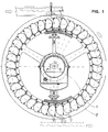
- Fig 1
- zeigt die Prinzipskizze der erfindungsgemäßen Wasserradturbine als Seitenansicht in einer bevorzugten Ausführung für die oberschlächtige Beaufschlagung.
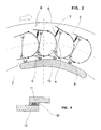
- Fig 2
- zeigt einen Ausschnitt aus Figur 1, im Schnitt.
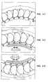
- Fig 3
- zeigt in einer Folge von Prinzipskizze die drei grundsätzlichen Betriebszustände einer erfindungsgemäßen Wasserradturbine, bzw. der Zellen derselben,nach Figur 1, und zwar mit geschlossenen Zellen während der Rotationsphase, sowie mit sich öffnenden und schließenden Zellen während der Phasen der Befüllung und Entleerung.
- Fig 4
- zeigt in einem Detailausschnitt von Figur 1 den Klappenverschluß einer Zelle.
- Fig 5
- zeigt den Ausschnitt einer Wasserradturbine von Figur 1, jedoch bei mittelschlächtiger Beaufschlagung.
- Fig 6
- zeigt den Ausschnitt einer Wasserradturbine von Figur 1, jedoch bei unterschlächtiger Beaufschlagung.
- Fig. 1
- shows the schematic diagram of the waterwheel turbine according to the invention as a side view in a preferred embodiment for the super-heavy loading.
- Fig. 2
- shows a section of Figure 1, in section.
- Fig 3
- shows in a sequence of schematic diagram the three basic operating states of a water wheel turbine according to the invention, or the cells thereof, according to Figure 1, with closed cells during the rotation phase, and with opening and closing cells during the filling and emptying phases.
- Fig. 4
- shows in a detail of Figure 1 the flap closure of a cell.
- Fig. 5
- shows the section of a waterwheel turbine of Figure 1, but with medium impact.
- Fig. 6
- shows the section of a water wheel turbine of Figure 1, but with undershot exposure.
Die Figuren zeigen eine bevorzugte Ausgestaltung der Wasserradturbine im
oberschlächtigen (Fig.1), im mittelschlächtigen (Fig.5) und im unterschlächtigen
(Fig.6) Betrieb. Den Figuren sind die verschiedenen, dem jeweiligen Betrieb
angepaßten bevorzugten Öffnungsweiten der Wasser-Verschlußklappen zu
entnehmen.
Eine gewichtssparende Rad-Hohlwelle (1) trägt die Nabe der Wasserradturbine und
verbindet letztere über Speichen mit zwei Radkränzen (9), welche als Träger der
Zellen (2) dienen und gleichzeitig die seitlichen Begrenzungen der geschlossenen
Zellen darstellen.
Die Befüllung einer Zelle mit Wasser erfolgt über die in der entsprechenden
Position geöffnete Verschlußklappe (3), welche über ein Gestänge(4) mit einer
Luftklappe (5) mechanisch verbunden ist. Die Klappenpaare werden jeweils über
eine Rolle (7) betätigt. Die Rolle dient als Übertragungselement für die
Steuerbefehle, welche beim Gleiten der Rollen über die Stirnseite einer profiliert
gekrümmten Kurvenscheibe (8) von dort übernommen werden und die
Klappenpaare auf- und zusteuern.
Die Figur 3.2 charakterisiert die sich kontinuierlich ändernden Klappenstellungen
beim Befüllen der Zellen, die Figur 3.3 die Zustände beim Entleeren der Zellen.The figures show a preferred embodiment of the waterwheel turbine in the overshot (Fig. 1), in the medium-sized (Fig. 5) and in the undershot (Fig. 6) operation. The figures show the various preferred opening widths of the water closure flaps, which are adapted to the respective operation.
A weight-saving hollow wheel shaft (1) carries the hub of the water wheel turbine and connects the latter via spokes to two wheel rims (9), which serve as supports for the cells (2) and at the same time represent the lateral boundaries of the closed cells.
A cell is filled with water via the closure flap (3) which is open in the corresponding position and which is mechanically connected to an air flap (5) via a linkage (4). The flap pairs are each operated via a roller (7). The roller serves as a transmission element for the control commands, which are taken over from there when the rollers slide over the end face of a profiled curved cam disc (8) and open and close the valve pairs.
Figure 3.2 characterizes the continuously changing valve positions when filling the cells, Figure 3.3 the states when emptying the cells.
Die abstandsfrei hintereinander angeordneten Zellen und die sich jeweils in Folge
ergebenden Stellungen der Verschlußklappen ermöglichen einen hohen
Befüllungsgrad.
Figur 4 zeigt nach einer bevorzugten Ausführung, wie sich die Zellen mittels
rechteckiger Profilstäbe (10) auf der Verschlußklappe (11) und auf der festen
Zellenwand (12) ausreichend abdichten lassen.
Das Öffnen der Klappenpaare erfolgt gegen die Federkraft der in Figur 2 besonders
übersichtlich dargestellten Zugfeder.
Die Zellen bleiben entsprechend Figur 3.1 während der Rotation der
Wasserradturbine geschlossen, um erst kurz vor dem tiefsten Rotationspunkt
mittels gleichartiger Steuerung, wie beim Befüllen, entleert zu werden.The cells, which are arranged one behind the other without a gap, and the positions of the closure flaps that result in each case enable a high degree of filling.
According to a preferred embodiment, FIG. 4 shows how the cells can be adequately sealed by means of rectangular profile bars (10) on the closure flap (11) and on the fixed cell wall (12).
The flap pairs are opened against the spring force of the tension spring shown particularly clearly in FIG.
According to FIG. 3.1, the cells remain closed during the rotation of the waterwheel turbine, in order to be emptied shortly before the deepest point of rotation by means of a control similar to that used for filling.
Die Luftklappe (5) jeder Zelle dient sowohl zur Entlüftung während der Befüllung,
als auch zur Belüftung bei der Entleerung.
Die wirkungsvolle Be- und Entlüftung der Zellen läßt sich mittels bekannter
Maßnahmen bei der Formgebung von Zellenwand und Klappen sicherstellen, z.B.
mittels Leitflossen in der Zelle.The air flap (5) of each cell serves both for ventilation during filling and for ventilation during emptying.
The effective ventilation of the cells can be ensured by means of known measures in the shaping of the cell wall and flaps, for example by means of guide fins in the cell.
Der hohe Wirkungsgrad der gezeigten Wasserradturbine in Nutzung der potentiellen Energie des Wassers wird durch zusätzliche Nutzung der Stoßenergie des ein- und ausströmenden Wassers nochmals nennenswert erhöht. Für die Nutzbarmachung der Stoßenergie des Wassers ist eine auf diesen Effekt genau abgestimmte Steuerung der Öffnungs- und Schließpunkte der Zellen während eines Radumlaufes entscheidend. Das läßt sich nur mit verschließbaren Zellen durchführen. The high efficiency of the waterwheel turbine shown using the potential energy of the water is generated by additional use of the impact energy of the inflowing and outflowing water increased significantly. For the Harnessing the impact energy of water is one of those effects coordinated control of the opening and closing points of the cells during a Wheel circulation crucial. This can only be done with lockable cells carry out.
Probleme bei der Wasser-Strahlabdeckung durch die Folgezelle, wie sie bei der Beaufschlagung von Rädern mit feststehenden Schaufeln bekannt sind, z.B. beim Peltonrad, treten bei der Wasserradturbine nicht auf, da dieser Effekt sich durch Anpassung der Winkelanstellung für die Verschlußklappe umgangen werden kann.Problems with the water jet coverage by the subsequent cell, as with the Loading of wheels with fixed blades is known, e.g. at the Pelton wheel, do not occur with the waterwheel turbine, because this effect is evident Adjustment of the angle setting for the closure flap can be avoided.
Die Kurvenscheibe ist ein Teil der gesamten, auf der Radwelle ortsfest gelagerten
Steuervorrichtung. Die Steuervorrichtung ist somit ein Anlagenteil, der seine
Position im Raum beibehält. Während die eine von zwei jeweils benötigten
Kurvenscheiben stets im Entleerungsbereich angeordnet sein wird, so läßt sich die
andere für den Einlaß benötigte Kurvenscheibe in jeder radialen Lage des Rades
positionieren, indem die zugehörigen Positionierungselemente entsprechend gegen
das ortsfeste Pendelgewicht ausgerichtet und mit diesem lösbar verbunden wird.
Die in Figur 1 auf den Positionierungselementen für die Kurvenscheibe
angebrachten Doppelpfeile deuten an, daß sich an diesen eine Feineinstellung der
Kurvenscheibe und damit eine Feinjustierung der Klappenbewegungen vornehmen
läßt.The cam disc is part of the entire control device which is mounted on the wheel shaft in a stationary manner. The control device is thus a part of the system that maintains its position in space. While one of the two required cam disks will always be arranged in the emptying area, the other cam disk required for the inlet can be positioned in any radial position of the wheel by appropriately aligning the associated positioning elements with the stationary pendulum weight and releasably connecting it.
The double arrows attached to the positioning elements for the cam disk in FIG. 1 indicate that a fine adjustment of the cam disk and thus a fine adjustment of the flap movements can be carried out on them.
Zur Sicherstellung des Selbstanlaufs der Wasserradturbine ist in jeder Zelle eine Wandbohrung (13) angebracht. Diese erlaubt, ausgehend von der Befüllung der Füllposition befindlichen Zelle ein langsames Befüllen der lagemäßig vorauseilenden Zellen solange, bis das Losbrechmoment für den Anlauf des Rades hergestellt ist.To ensure that the waterwheel turbine starts up automatically, there is one in each cell Wall hole (13) attached. Based on the filling of the Filling position a slow filling of the leading position Cells until the breakaway torque for starting the wheel is established.
Claims (9)
dadurch gekennzeichnet, daß
jede Zellenöffnung eine Verschlußklappe (3) besitzt, daß die Verschlußklappe über ein Gestänge (4) mit einer zweiten, zur Ent- und Belüftung dienenden Luftklappe (5) mechanisch verbunden ist und daß die Wasserradturbine eine ortsfeste Steuervorrichtung und mechanische Übertragungselemente zum jeweils gleichzeitigen Öffnen und Schließen von Verschluß- und Luftklappe besitzt.Water wheel turbine for hydropower plants using the drop height of the water, with a horizontal wheel shaft (1) and a plurality of cells which are closed at the end and absorb water and emit water via cell openings and are arranged on the wall (2),
characterized in that
Each cell opening has a closure flap (3) that the closure flap is mechanically connected via a linkage (4) to a second air flap (5) serving for ventilation and ventilation, and that the waterwheel turbine has a fixed control device and mechanical transmission elements for the simultaneous opening and opening Has closure of the flap and air flap.
Priority Applications (12)
| Application Number | Priority Date | Filing Date | Title |
|---|---|---|---|
| ES98106230T ES2141626T3 (en) | 1998-04-06 | 1998-04-06 | HYDRAULIC WHEEL TURBINE FOR HYDRAULIC ENERGY GENERATORS. |
| DK98106230T DK0940576T3 (en) | 1998-04-06 | 1998-04-06 | Hydroelectric turbine for hydropower plants |
| DE59800037T DE59800037D1 (en) | 1998-04-06 | 1998-04-06 | Water wheel turbine for hydropower plants |
| EP98106230A EP0940576B1 (en) | 1998-04-06 | 1998-04-06 | Waterwheel |
| AT98106230T ATE185611T1 (en) | 1998-04-06 | 1998-04-06 | WATERWHEEL TURBINE FOR HYDROPOWER PLANTS |
| JP55006599A JP2002503309A (en) | 1998-04-06 | 1999-04-06 | Hydro turbine turbine |
| KR19997011433A KR20010013432A (en) | 1998-04-06 | 1999-04-06 | Water wheel turbine for water power stations |
| PCT/EP1999/002317 WO1999051876A1 (en) | 1998-04-06 | 1999-04-06 | Water wheel turbine for water power stations |
| CA002293542A CA2293542A1 (en) | 1998-04-06 | 1999-04-06 | Water wheel turbine for water power stations |
| US09/445,280 US6210113B1 (en) | 1998-04-06 | 1999-04-06 | Water wheel turbine for water power stations |
| BR9906315-8A BR9906315A (en) | 1998-04-06 | 1999-04-06 | Hydraulic turbine-wheel for hydroelectric installations |
| GR20000400027T GR3032329T3 (en) | 1998-04-06 | 2000-01-11 | Waterwheel |
Applications Claiming Priority (1)
| Application Number | Priority Date | Filing Date | Title |
|---|---|---|---|
| EP98106230A EP0940576B1 (en) | 1998-04-06 | 1998-04-06 | Waterwheel |
Publications (2)
| Publication Number | Publication Date |
|---|---|
| EP0940576A1 true EP0940576A1 (en) | 1999-09-08 |
| EP0940576B1 EP0940576B1 (en) | 1999-10-13 |
Family
ID=8231721
Family Applications (1)
| Application Number | Title | Priority Date | Filing Date |
|---|---|---|---|
| EP98106230A Expired - Lifetime EP0940576B1 (en) | 1998-04-06 | 1998-04-06 | Waterwheel |
Country Status (12)
| Country | Link |
|---|---|
| US (1) | US6210113B1 (en) |
| EP (1) | EP0940576B1 (en) |
| JP (1) | JP2002503309A (en) |
| KR (1) | KR20010013432A (en) |
| AT (1) | ATE185611T1 (en) |
| BR (1) | BR9906315A (en) |
| CA (1) | CA2293542A1 (en) |
| DE (1) | DE59800037D1 (en) |
| DK (1) | DK0940576T3 (en) |
| ES (1) | ES2141626T3 (en) |
| GR (1) | GR3032329T3 (en) |
| WO (1) | WO1999051876A1 (en) |
Cited By (6)
| Publication number | Priority date | Publication date | Assignee | Title |
|---|---|---|---|---|
| DE10218443A1 (en) * | 2002-04-25 | 2003-11-20 | Hartmuth Drews | Segmented rim water wheel has at least 16 identical, essentially overlapping, flexurally stiff, mutually joined rim segments with side plates stiffened by water blades, joined in force-locking manner |
| EP1522723A1 (en) * | 2003-10-06 | 2005-04-13 | Ihrenberger, Adolf, Dipl.-Ing. (FH) | Bucket for waterwheel |
| CN103256909A (en) * | 2013-02-28 | 2013-08-21 | 华北水利水电学院 | Roundness measurement device for turbine runner examination and repair |
| CN103353271A (en) * | 2013-07-12 | 2013-10-16 | 华北水利水电大学 | Circularity measuring device for maintaining runner chamber of water turbine |
| CN105240041A (en) * | 2015-11-17 | 2016-01-13 | 中国长江三峡集团公司 | Ventilating smoke dissipating system used for underground cavern construction of large hydropower station |
| EP3633185A1 (en) | 2018-10-05 | 2020-04-08 | Rouille, Eugène | Bucket intended to equip a water wheel of a hydrokinetic machine |
Families Citing this family (33)
| Publication number | Priority date | Publication date | Assignee | Title |
|---|---|---|---|---|
| FR2802247B1 (en) * | 1999-12-10 | 2002-01-11 | Abb Alstom Power Hydro | METHOD FOR ASSEMBLING A PELTON-TYPE TURBINE WHEEL, AUGET OF SUCH A WHEEL AND TURBINE WHEEL EQUIPPED WITH SUCH A AUGET |
| ES2182681B1 (en) * | 2001-03-06 | 2004-06-01 | Justo Salgado Tavares | HYDROELECTRIC POWER PLANT OF MILLS. |
| KR20030034658A (en) * | 2001-10-26 | 2003-05-09 | 변동춘 | Rotetion lmcreasing tecity of waten wheel |
| US6935832B1 (en) | 2002-05-21 | 2005-08-30 | Natural Forces, Llc | Portable power generating devices |
| US20040033129A1 (en) * | 2002-08-10 | 2004-02-19 | Jackson Robert William | Pinwheel turbine |
| AU2003224205A1 (en) * | 2002-11-22 | 2004-06-18 | Christophe Fonfrede | Hydraulic wheel |
| FR2849679A1 (en) * | 2003-01-08 | 2004-07-09 | Michel Fonfrede | Power generation water turbine has water level control sluice integrated into centre of turbine ring |
| US7478811B2 (en) * | 2004-08-02 | 2009-01-20 | Garrett Johnson | Wave driven gaming apparatus |
| US7235893B2 (en) * | 2005-04-14 | 2007-06-26 | Platt Michael D | Reduced friction wind turbine apparatus and method |
| US7633177B2 (en) * | 2005-04-14 | 2009-12-15 | Natural Forces, Llc | Reduced friction wind turbine apparatus and method |
| ES2342865B1 (en) * | 2007-07-04 | 2011-05-16 | Andres Ignacio Plaza Rodriguez | CLOSURE VALVE OF THE AIR OUTLET HOLE OF THE CANGILON DE LA NORIA. |
| US7586207B2 (en) * | 2007-12-05 | 2009-09-08 | Kinetic Wave Power | Water wave power system |
| US7478974B1 (en) | 2008-04-17 | 2009-01-20 | William Lowell Kelly | Apparatus for hydroelectric power production expansion |
| US20100001530A1 (en) * | 2008-06-03 | 2010-01-07 | Chang Nelson N S | "Sandwich" multiple hydro turbine power driver technology |
| FR2945585A1 (en) * | 2009-05-12 | 2010-11-19 | Ile De Gestion F F F Soc Civ | AUBES PRESSURE WHEEL |
| US9593665B2 (en) | 2009-10-02 | 2017-03-14 | Jose Ramon Santana | Hydro-kinetic transport wheel |
| US20110080002A1 (en) * | 2009-10-02 | 2011-04-07 | Jose Ramon Santana | Controlled momentum hydro-electric system |
| US10851758B2 (en) * | 2009-10-02 | 2020-12-01 | Jose Ramon Santana | Hydrokinetic transport wheel mount |
| JP4566287B1 (en) * | 2010-06-17 | 2010-10-20 | 勇 佐藤 | Hydraulic drive |
| US8881517B2 (en) * | 2010-06-29 | 2014-11-11 | Azizollah Khesali | Water-wave/flowing-water energy transformer |
| US8307640B1 (en) * | 2011-10-05 | 2012-11-13 | Callen Dennis M | Apparatus for generating power |
| WO2015077704A1 (en) | 2013-11-22 | 2015-05-28 | Garrett Johnson | System and method for rider propulsion |
| US9890761B2 (en) | 2014-01-22 | 2018-02-13 | Gene D. Kasten | System and method for low ecology impact generation of hydroelectric power |
| US9562511B2 (en) | 2014-01-22 | 2017-02-07 | Gene D. Kasten | System and method for low ecology impact generation of hydroelectric power |
| US20170082085A1 (en) * | 2015-09-22 | 2017-03-23 | Robert L. Huebner | Waterwheel for a Waterwheel Energy System |
| US20160273511A1 (en) * | 2014-09-23 | 2016-09-22 | Robert L. Huebner | Waterwheel for a Waterwheel Energy System |
| US20160084217A1 (en) * | 2014-09-23 | 2016-03-24 | Robert L. Huebner | Waterwheel Energy System |
| US9863397B2 (en) * | 2014-10-21 | 2018-01-09 | Andreas Haikalis | Machine for generating power by rotating metal pinwheels via hydraulic and gravitational forces |
| US10844828B2 (en) | 2016-06-01 | 2020-11-24 | Robert L. Huebner | Water powered motor for producing useful work |
| CN106837654B (en) * | 2017-02-18 | 2019-02-19 | 深圳市中科智诚科技有限公司 | A kind of horizontal axis impulse turbine that generating efficiency is high |
| US10715009B1 (en) * | 2019-05-01 | 2020-07-14 | Gene D. Kasten | Hydro electric power generation system |
| KR102267963B1 (en) * | 2020-07-06 | 2021-06-23 | 코리아엔텍 주식회사 | Small hydro power generator |
| US12018636B1 (en) | 2022-05-27 | 2024-06-25 | Anthony F. Kroboth | Bucket assembly with containment flap for gravity-type hydropower apparatus |
Citations (7)
| Publication number | Priority date | Publication date | Assignee | Title |
|---|---|---|---|---|
| DE370513C (en) * | 1922-08-11 | 1923-03-03 | Bedford Jones | water wheel |
| US1773010A (en) * | 1929-04-01 | 1930-08-12 | Rixe Carl | Water wheel |
| FR1078558A (en) * | 1953-03-31 | 1954-11-19 | Improvements to hydraulic wheels | |
| US4385497A (en) * | 1981-08-03 | 1983-05-31 | Scott Dan J | Propulsion system for water wheel |
| DE3621312A1 (en) | 1986-06-25 | 1988-01-28 | Hans Bierner | Gravitation reactor, gravitator for short, in imitation of a water wheel |
| DE4339236C1 (en) * | 1993-11-12 | 1995-05-11 | Heinz Noack | Through-flow turbine |
| DE19517261A1 (en) * | 1995-05-11 | 1996-11-14 | Kurt Willig | Strip wheel for hydraulic power transmission |
Family Cites Families (4)
| Publication number | Priority date | Publication date | Assignee | Title |
|---|---|---|---|---|
| US194897A (en) * | 1877-09-04 | Improvement in water-wheels | ||
| US652852A (en) * | 1899-10-02 | 1900-07-03 | Hosea W Libbey | Motor-wheel for vehicles. |
| US818825A (en) * | 1904-09-22 | 1906-04-24 | James Amers Hicks | Feathering-blade paddle-wheel. |
| US1361467A (en) * | 1919-05-17 | 1920-12-07 | Kincaid John | Impact and reaction water-wheel |
-
1998
- 1998-04-06 DK DK98106230T patent/DK0940576T3/en active
- 1998-04-06 ES ES98106230T patent/ES2141626T3/en not_active Expired - Lifetime
- 1998-04-06 DE DE59800037T patent/DE59800037D1/en not_active Expired - Fee Related
- 1998-04-06 EP EP98106230A patent/EP0940576B1/en not_active Expired - Lifetime
- 1998-04-06 AT AT98106230T patent/ATE185611T1/en not_active IP Right Cessation
-
1999
- 1999-04-06 WO PCT/EP1999/002317 patent/WO1999051876A1/en not_active Application Discontinuation
- 1999-04-06 KR KR19997011433A patent/KR20010013432A/en not_active Application Discontinuation
- 1999-04-06 JP JP55006599A patent/JP2002503309A/en active Pending
- 1999-04-06 CA CA002293542A patent/CA2293542A1/en not_active Abandoned
- 1999-04-06 US US09/445,280 patent/US6210113B1/en not_active Expired - Fee Related
- 1999-04-06 BR BR9906315-8A patent/BR9906315A/en not_active Application Discontinuation
-
2000
- 2000-01-11 GR GR20000400027T patent/GR3032329T3/en not_active IP Right Cessation
Patent Citations (7)
| Publication number | Priority date | Publication date | Assignee | Title |
|---|---|---|---|---|
| DE370513C (en) * | 1922-08-11 | 1923-03-03 | Bedford Jones | water wheel |
| US1773010A (en) * | 1929-04-01 | 1930-08-12 | Rixe Carl | Water wheel |
| FR1078558A (en) * | 1953-03-31 | 1954-11-19 | Improvements to hydraulic wheels | |
| US4385497A (en) * | 1981-08-03 | 1983-05-31 | Scott Dan J | Propulsion system for water wheel |
| DE3621312A1 (en) | 1986-06-25 | 1988-01-28 | Hans Bierner | Gravitation reactor, gravitator for short, in imitation of a water wheel |
| DE4339236C1 (en) * | 1993-11-12 | 1995-05-11 | Heinz Noack | Through-flow turbine |
| DE19517261A1 (en) * | 1995-05-11 | 1996-11-14 | Kurt Willig | Strip wheel for hydraulic power transmission |
Non-Patent Citations (1)
| Title |
|---|
| KOENING, JEHLE, C.F. MUELLER VERLAG: "Völlig neu Überarbeitete", BAU VON WASSERKRAFTANLAGEN, PROXISBEZOGENE PLANUNGSUNTERLAGEN, 1997, pages 197 |
Cited By (10)
| Publication number | Priority date | Publication date | Assignee | Title |
|---|---|---|---|---|
| DE10218443A1 (en) * | 2002-04-25 | 2003-11-20 | Hartmuth Drews | Segmented rim water wheel has at least 16 identical, essentially overlapping, flexurally stiff, mutually joined rim segments with side plates stiffened by water blades, joined in force-locking manner |
| DE10218443B4 (en) * | 2002-04-25 | 2004-05-13 | Hartmuth Drews | Segment Wreath waterwheel |
| EP1522723A1 (en) * | 2003-10-06 | 2005-04-13 | Ihrenberger, Adolf, Dipl.-Ing. (FH) | Bucket for waterwheel |
| CN103256909A (en) * | 2013-02-28 | 2013-08-21 | 华北水利水电学院 | Roundness measurement device for turbine runner examination and repair |
| CN103256909B (en) * | 2013-02-28 | 2015-12-02 | 华北水利水电大学 | Rotary wheel of water turbine maintenance roundness measuring device |
| CN103353271A (en) * | 2013-07-12 | 2013-10-16 | 华北水利水电大学 | Circularity measuring device for maintaining runner chamber of water turbine |
| CN103353271B (en) * | 2013-07-12 | 2015-12-09 | 华北水利水电大学 | Turbine chamber maintenance roundness measuring device |
| CN105240041A (en) * | 2015-11-17 | 2016-01-13 | 中国长江三峡集团公司 | Ventilating smoke dissipating system used for underground cavern construction of large hydropower station |
| EP3633185A1 (en) | 2018-10-05 | 2020-04-08 | Rouille, Eugène | Bucket intended to equip a water wheel of a hydrokinetic machine |
| FR3086979A1 (en) * | 2018-10-05 | 2020-04-10 | Eugene Rouille | AUGET FOR FITTING THE AUGET WHEEL OF A HYDROLIAN MACHINE |
Also Published As
| Publication number | Publication date |
|---|---|
| ES2141626T3 (en) | 2000-03-16 |
| CA2293542A1 (en) | 1999-10-14 |
| EP0940576B1 (en) | 1999-10-13 |
| WO1999051876A1 (en) | 1999-10-14 |
| KR20010013432A (en) | 2001-02-26 |
| ATE185611T1 (en) | 1999-10-15 |
| GR3032329T3 (en) | 2000-04-27 |
| DK0940576T3 (en) | 2000-04-25 |
| US6210113B1 (en) | 2001-04-03 |
| JP2002503309A (en) | 2002-01-29 |
| DE59800037D1 (en) | 1999-11-18 |
| BR9906315A (en) | 2000-07-11 |
Similar Documents
| Publication | Publication Date | Title |
|---|---|---|
| EP0940576B1 (en) | Waterwheel | |
| DE69729552T2 (en) | MAGNUS EFFECT WIND TURBINE | |
| EP1177381B1 (en) | Wind power facility with a vertical rotor | |
| EP2007982A1 (en) | Apparatus for use of flow energy | |
| DE3035458C2 (en) | ||
| CH706768A1 (en) | Plant for extracting electrical energy from hydropower. | |
| WO2010097204A2 (en) | Water wheel | |
| DE4223971A1 (en) | Paddle blade system for utilising wind or water power to produce e.g. electric power - is designed, e.g. as frameless, large area kinetic plates arranged respectively against open carrier frames in any number around paddle wheel shaft | |
| DE4319291C1 (en) | Rotor on vertical axis for wind-energy converter | |
| DE69510322T2 (en) | GENERATION OF ELECTRIC ENERGY BY WIND DRIVE DEVICE | |
| EP1144865B1 (en) | Method for utilizing the energy of wind or water | |
| DE3501807A1 (en) | Fluid-flow engine for obtaining energy | |
| DE29980074U1 (en) | Flow energy system | |
| DE69409389T2 (en) | TURBINE | |
| AT410576B (en) | DEVICE AND METHOD FOR GENERATING ELECTRICAL ENERGY | |
| DE102010052947B4 (en) | Wind direction-independent wind turbine with vertical rotor, multi-row inlet surface construction and drop-shaped profiled rotor blades | |
| DE10032674A1 (en) | Rotor for utilizing energy of flowing medium has rotor blades guided so that blades present minimum opposition when rotating against wind | |
| DD154905A5 (en) | HYDRODYNAMIC ELECTRICAL GENERATOR SYSTEM | |
| DE102010054794A1 (en) | Rotor for energy conversion machine for converting energy of fluid flow extending in fixed direction and variable directions, particularly orbitally in rotation of rotor shaft, has resistor element, which is fastened to rotor shaft | |
| DE10022117A1 (en) | Fluid flow machine e.g. water wheel for converting flow energy of flowing medium into rotational energy, comprises vane wheel located rotatable on vertical shaft which is arranged lying in liquid flow and swivelable vanes | |
| EP3737855B1 (en) | Water and/or wind power plant | |
| WO2013084196A1 (en) | Wind turbine | |
| DE8228078U1 (en) | VERTICAL AXIS ROTOR | |
| DE3933531A1 (en) | Vertical axis portable wind-powered generator - makes use of flaps with variable profile hinged sections | |
| AT512564A1 (en) | Wind turbine and method for generating rotary energy by wind |
Legal Events
| Date | Code | Title | Description |
|---|---|---|---|
| GRAG | Despatch of communication of intention to grant |
Free format text: ORIGINAL CODE: EPIDOS AGRA |
|
| GRAG | Despatch of communication of intention to grant |
Free format text: ORIGINAL CODE: EPIDOS AGRA |
|
| GRAH | Despatch of communication of intention to grant a patent |
Free format text: ORIGINAL CODE: EPIDOS IGRA |
|
| GRAH | Despatch of communication of intention to grant a patent |
Free format text: ORIGINAL CODE: EPIDOS IGRA |
|
| PUAI | Public reference made under article 153(3) epc to a published international application that has entered the european phase |
Free format text: ORIGINAL CODE: 0009012 |
|
| GRAA | (expected) grant |
Free format text: ORIGINAL CODE: 0009210 |
|
| 17P | Request for examination filed |
Effective date: 19981001 |
|
| AK | Designated contracting states |
Kind code of ref document: A1 Designated state(s): AT BE CH CY DE DK ES FI FR GB GR IE IT LI LU MC NL PT SE |
|
| AX | Request for extension of the european patent |
Free format text: AL;LT;LV;MK;RO;SI |
|
| AK | Designated contracting states |
Kind code of ref document: B1 Designated state(s): AT CH DE DK ES FI FR GB GR IT LI SE |
|
| AX | Request for extension of the european patent |
Free format text: AL;LT;LV;MK;RO;SI |
|
| REF | Corresponds to: |
Ref document number: 185611 Country of ref document: AT Date of ref document: 19991015 Kind code of ref document: T |
|
| REG | Reference to a national code |
Ref country code: CH Ref legal event code: EP |
|
| REF | Corresponds to: |
Ref document number: 59800037 Country of ref document: DE Date of ref document: 19991118 |
|
| ITF | It: translation for a ep patent filed | ||
| REG | Reference to a national code |
Ref country code: IE Ref legal event code: FG4D Free format text: GERMAN |
|
| GBT | Gb: translation of ep patent filed (gb section 77(6)(a)/1977) |
Effective date: 20000114 |
|
| ET | Fr: translation filed | ||
| REG | Reference to a national code |
Ref country code: ES Ref legal event code: FG2A Ref document number: 2141626 Country of ref document: ES Kind code of ref document: T3 |
|
| REG | Reference to a national code |
Ref country code: DK Ref legal event code: T3 |
|
| AKX | Designation fees paid |
Free format text: AT CH DE DK ES FI FR GB GR IT LI SE |
|
| PLBE | No opposition filed within time limit |
Free format text: ORIGINAL CODE: 0009261 |
|
| STAA | Information on the status of an ep patent application or granted ep patent |
Free format text: STATUS: NO OPPOSITION FILED WITHIN TIME LIMIT |
|
| 26N | No opposition filed | ||
| REG | Reference to a national code |
Ref country code: IE Ref legal event code: FD4D |
|
| PGFP | Annual fee paid to national office [announced via postgrant information from national office to epo] |
Ref country code: FI Payment date: 20010329 Year of fee payment: 4 |
|
| PGFP | Annual fee paid to national office [announced via postgrant information from national office to epo] |
Ref country code: SE Payment date: 20010402 Year of fee payment: 4 |
|
| REG | Reference to a national code |
Ref country code: GB Ref legal event code: IF02 |
|
| PGFP | Annual fee paid to national office [announced via postgrant information from national office to epo] |
Ref country code: DK Payment date: 20020327 Year of fee payment: 5 |
|
| PGFP | Annual fee paid to national office [announced via postgrant information from national office to epo] |
Ref country code: GR Payment date: 20020329 Year of fee payment: 5 |
|
| PGFP | Annual fee paid to national office [announced via postgrant information from national office to epo] |
Ref country code: GB Payment date: 20020402 Year of fee payment: 5 |
|
| PG25 | Lapsed in a contracting state [announced via postgrant information from national office to epo] |
Ref country code: FI Free format text: LAPSE BECAUSE OF NON-PAYMENT OF DUE FEES Effective date: 20020406 |
|
| PG25 | Lapsed in a contracting state [announced via postgrant information from national office to epo] |
Ref country code: SE Free format text: LAPSE BECAUSE OF NON-PAYMENT OF DUE FEES Effective date: 20020407 |
|
| PGFP | Annual fee paid to national office [announced via postgrant information from national office to epo] |
Ref country code: FR Payment date: 20020416 Year of fee payment: 5 |
|
| PGFP | Annual fee paid to national office [announced via postgrant information from national office to epo] |
Ref country code: ES Payment date: 20020418 Year of fee payment: 5 |
|
| PG25 | Lapsed in a contracting state [announced via postgrant information from national office to epo] |
Ref country code: LI Free format text: LAPSE BECAUSE OF NON-PAYMENT OF DUE FEES Effective date: 20020430 Ref country code: CH Free format text: LAPSE BECAUSE OF NON-PAYMENT OF DUE FEES Effective date: 20020430 |
|
| EUG | Se: european patent has lapsed |
Ref document number: 98106230.0 |
|
| REG | Reference to a national code |
Ref country code: CH Ref legal event code: PL |
|
| PGFP | Annual fee paid to national office [announced via postgrant information from national office to epo] |
Ref country code: DE Payment date: 20030331 Year of fee payment: 6 |
|
| PGFP | Annual fee paid to national office [announced via postgrant information from national office to epo] |
Ref country code: AT Payment date: 20030403 Year of fee payment: 6 |
|
| PG25 | Lapsed in a contracting state [announced via postgrant information from national office to epo] |
Ref country code: GB Free format text: LAPSE BECAUSE OF NON-PAYMENT OF DUE FEES Effective date: 20030406 |
|
| PG25 | Lapsed in a contracting state [announced via postgrant information from national office to epo] |
Ref country code: ES Free format text: LAPSE BECAUSE OF NON-PAYMENT OF DUE FEES Effective date: 20030407 |
|
| PG25 | Lapsed in a contracting state [announced via postgrant information from national office to epo] |
Ref country code: DK Free format text: LAPSE BECAUSE OF NON-PAYMENT OF DUE FEES Effective date: 20030430 |
|
| PG25 | Lapsed in a contracting state [announced via postgrant information from national office to epo] |
Ref country code: GR Free format text: LAPSE BECAUSE OF NON-PAYMENT OF DUE FEES Effective date: 20031104 |
|
| GBPC | Gb: european patent ceased through non-payment of renewal fee |
Effective date: 20030406 |
|
| REG | Reference to a national code |
Ref country code: DK Ref legal event code: EBP |
|
| PG25 | Lapsed in a contracting state [announced via postgrant information from national office to epo] |
Ref country code: FR Free format text: LAPSE BECAUSE OF NON-PAYMENT OF DUE FEES Effective date: 20031231 |
|
| REG | Reference to a national code |
Ref country code: FR Ref legal event code: ST |
|
| PG25 | Lapsed in a contracting state [announced via postgrant information from national office to epo] |
Ref country code: AT Free format text: LAPSE BECAUSE OF NON-PAYMENT OF DUE FEES Effective date: 20040406 |
|
| REG | Reference to a national code |
Ref country code: ES Ref legal event code: FD2A Effective date: 20030407 |
|
| PG25 | Lapsed in a contracting state [announced via postgrant information from national office to epo] |
Ref country code: DE Free format text: LAPSE BECAUSE OF NON-PAYMENT OF DUE FEES Effective date: 20041103 |
|
| PG25 | Lapsed in a contracting state [announced via postgrant information from national office to epo] |
Ref country code: IT Free format text: LAPSE BECAUSE OF NON-PAYMENT OF DUE FEES;WARNING: LAPSES OF ITALIAN PATENTS WITH EFFECTIVE DATE BEFORE 2007 MAY HAVE OCCURRED AT ANY TIME BEFORE 2007. THE CORRECT EFFECTIVE DATE MAY BE DIFFERENT FROM THE ONE RECORDED. Effective date: 20050406 |