EP0940554B1 - Roller shutter control device - Google Patents
Roller shutter control deviceInfo
- Publication number
- EP0940554B1 EP0940554B1 EP99104415A EP99104415A EP0940554B1 EP 0940554 B1 EP0940554 B1 EP 0940554B1 EP 99104415 A EP99104415 A EP 99104415A EP 99104415 A EP99104415 A EP 99104415A EP 0940554 B1 EP0940554 B1 EP 0940554B1
- Authority
- EP
- European Patent Office
- Prior art keywords
- end position
- roller blind
- drape
- user
- reached
- Prior art date
- Legal status (The legal status is an assumption and is not a legal conclusion. Google has not performed a legal analysis and makes no representation as to the accuracy of the status listed.)
- Expired - Lifetime
Links
Images


Classifications
-
- E—FIXED CONSTRUCTIONS
- E06—DOORS, WINDOWS, SHUTTERS, OR ROLLER BLINDS IN GENERAL; LADDERS
- E06B—FIXED OR MOVABLE CLOSURES FOR OPENINGS IN BUILDINGS, VEHICLES, FENCES OR LIKE ENCLOSURES IN GENERAL, e.g. DOORS, WINDOWS, BLINDS, GATES
- E06B9/00—Screening or protective devices for wall or similar openings, with or without operating or securing mechanisms; Closures of similar construction
- E06B9/56—Operating, guiding or securing devices or arrangements for roll-type closures; Spring drums; Tape drums; Counterweighting arrangements therefor
- E06B9/80—Safety measures against dropping or unauthorised opening; Braking or immobilising devices; Devices for limiting unrolling
- E06B9/82—Safety measures against dropping or unauthorised opening; Braking or immobilising devices; Devices for limiting unrolling automatic
- E06B9/88—Safety measures against dropping or unauthorised opening; Braking or immobilising devices; Devices for limiting unrolling automatic for limiting unrolling
-
- E—FIXED CONSTRUCTIONS
- E06—DOORS, WINDOWS, SHUTTERS, OR ROLLER BLINDS IN GENERAL; LADDERS
- E06B—FIXED OR MOVABLE CLOSURES FOR OPENINGS IN BUILDINGS, VEHICLES, FENCES OR LIKE ENCLOSURES IN GENERAL, e.g. DOORS, WINDOWS, BLINDS, GATES
- E06B9/00—Screening or protective devices for wall or similar openings, with or without operating or securing mechanisms; Closures of similar construction
- E06B9/56—Operating, guiding or securing devices or arrangements for roll-type closures; Spring drums; Tape drums; Counterweighting arrangements therefor
- E06B9/68—Operating devices or mechanisms, e.g. with electric drive
- E06B2009/6809—Control
- E06B2009/6818—Control using sensors
- E06B2009/6854—Control using sensors sensing torque
-
- E—FIXED CONSTRUCTIONS
- E06—DOORS, WINDOWS, SHUTTERS, OR ROLLER BLINDS IN GENERAL; LADDERS
- E06B—FIXED OR MOVABLE CLOSURES FOR OPENINGS IN BUILDINGS, VEHICLES, FENCES OR LIKE ENCLOSURES IN GENERAL, e.g. DOORS, WINDOWS, BLINDS, GATES
- E06B9/00—Screening or protective devices for wall or similar openings, with or without operating or securing mechanisms; Closures of similar construction
- E06B9/56—Operating, guiding or securing devices or arrangements for roll-type closures; Spring drums; Tape drums; Counterweighting arrangements therefor
- E06B9/68—Operating devices or mechanisms, e.g. with electric drive
- E06B2009/6809—Control
- E06B2009/6872—Control using counters to determine shutter position
Definitions
- roller shutter controls can thereby raise roller shutter controls, as they come with retrofittable roller shutter drives used. In such roller shutter drives no limit switches are available or possible to detect the position of the blinds curtain directly.
- the upper and lower physical end position of the roller blind curtain is measured indirectly via this counter and the drive shut down accordingly.
- roller shutter controls As they come with retrofittable roller shutter drives used.
- Such drives are usually drives which co-operate with the existing tension belt of the shutter, i. Drives that do not sit in the winding shaft of the roller shutter and have mechanically adjustable limit switch contacts arranged in the winding shaft.
- Object of the present invention is therefore to provide a roller shutter control in which the upper end position does not change over time.
- the solution according to the invention makes it possible to provide two directional keys on the housing and also to label accordingly, so that self-explanatory operation results for the minimum scope of performance.
- the program in the control device is designed in such a way that the drive for the roller shutter belt can be set in motion and switched off at any time with the aid of the travel direction keys.
- the user is not dependent on performing an initialization run first after installation or a power failure. He is thus able to have a minimum level of performance that he can use even if the manual is lost or out of reach.
- the slats of the roller shutter curtain usually have in the connecting ribs slits that allow air to pass through and also a passage of light, as long as the slats do not sit tightly.
- the user-defined end position can be used to keep these slots in the open position so that both light and air can pass through.
- a lower but also an upper end position can be arbitrarily set by the user, in addition a complete opening can be suppressed, which is useful, for example, for shading in the summer.
- These user-defined limit positions can be programmed using only one additional key, a settaste. There are several options to choose from.
- the user-programmed end position can be achieved by moving the roller shutter in the relevant direction to the end position in which the user-defined end position is to be set starting from a middle position. For this purpose, the user can first press a settable and then when reaching the desired position by pressing any of the keys again stop the blinds curtain, whereby the upper end position is defined.
- Another conceivable possibility is to set the shutter curtain as usual in motion and by pressing the settest stop both the movement as well as in the control to save a corresponding state, as determined final position.
- This may be, for example, a count arbitrarily set in the controller when the controller cooperates with a pulser driven by the roller shutter belt.
- the drive is only kept running until the relevant counter reading is reached.
- a discrete digital counter is not necessarily used for this purpose, but that this counter is reproduced by means of a microprocessor and a program contained therein.
- the controller can be designed so that it searches itself - without intervention by the user, the upper and / or lower limit position itself, in which the shutter curtain can be moved due to the spatial conditions, searches automatically.
- This automatic search of the limit positions can be triggered by the user by pressing the corresponding direction key, the blinds curtain starts in the appropriate direction.
- Another possibility is, when switching on a power supply voltage for the controller for the first time, which is equivalent to a voltage recovery after a power failure, the roller shutter curtain automatically performs an initialization.
- a manually controlled initialization run is preferable in order to avoid unattended collisions with any objects located in the area of the blinds curtain, for example flower pots.
- An easy way to determine the physical end positions is to monitor the power consumption of the drive motor. Once the power consumption over rises to a predetermined limit, this is detected as a signal that the shutter curtain has reached its upper end position and the attacks, which are usually provided on the shutter curtain, rest against the shutter box. The lower end position is signaled to the system when the pulses from the pulser fail because the tension belt relaxes when the roller shutter is fully closed.
- a counter may be used which in turn is not necessarily a discrete counter, but is modeled in a microprocessor by means of a program. This counter is set to a predetermined value and, starting from this state when the shutter curtain is lowered, the counter value is counted until the count pulses fail.
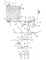
- the arrangement has a roller shutter 1, which can be set via a drive device 2 optionally in motion.
- the control of the drive device 2 takes place with the aid of a control device 3.
- To the shutter 1 includes a winding shaft 4, which is rotatably mounted at both ends via pins 5 and 6 in a non-illustrated shutter box.
- a roller shutter curtain 7 is fixed with one edge, which consists of a plurality of mutually parallel roller shutter slats 8, which are coupled together via a tongue-and-groove connection. Its lower edge is formed by a closing strip 9, are fixed to the two stops 11 rigid.
- the stops 11 in the form of cylindrical pins can rest against the edge of the slot of the roller shutter box, not shown, in order to prevent the roller shutter curtain 7 disappears completely in the roller shutter box. They work so far together with the slot of the roller shutter box as a mechanical end stop.
- a belt pulley 12 is arranged, which is rotatably connected to the winding shaft 4.
- a tension belt 13 can be wound, which is fixed with one end on the belt pulley 12.
- the belt pulley 12 is, as usual in roll shops, a flanged wheel to prevent a lateral run down of the tension belt 13.
- the tension belt 13 is symbolically illustrated in its lower end in Fig. 1 in the form of a dashed line.
- the drive device 2 which interacts with the tension belt 13 at the lower end, is shown in a highly schematized manner and also rotated by 90 ° in order to be able to illustrate the course of the tension belt 13.
- To the drive means 2 include a first friction roller 14 which is driven via a permanent-magnet DC motor 15 with reduction gear, two further friction rollers 16 and 17 which are non-rotatably connected via not shown spur gears with the friction roller 14 and axially parallel to this, as well as in the Wall of the relevant building accommodated automatic winding 18 with a belt pulley 19 which is biased by a symbolically indicated spring 21 in the winding direction of the tension belt 13.
- the lower end of the tension belt 13 is mounted on the disc 19, so that by means of the spring 21, which acts as a spring motor, the portion of the tension belt 13 between the friction roller 17 and the take-up disc 19 is kept taut.
- the motor 15 and the friction rollers 14, 16 and 17 are arranged and stored together in a non-illustrated board.
- a sensing roller 22 is also rotatably mounted, namely about an axis which is parallel to the axes of the friction rollers 14, 16 and 17 and the take-up disc 19.
- the sensing roller 22 is arranged so that the tensioned tension belt 13 runs over the peripheral surface and the follower roller 22 can take by friction.
- a disc 23 is rotatably coupled, which is scanned by a sensor 24.
- the sensor 24 may be an optical or a magnetic field sensor which senses irregularities on the disk 23 and emits an electrical pulse via a connecting line 25 at each pass of nonuniformity.
- the number of pulses delivered is proportional to the distance traveled by the tension belt 13.
- the core of the control device 3 forms a microcontroller or microprocessor 26, which has a plurality of inputs 27, 28, 29, 31 and 32 and a control output 33.
- a microcontroller or microprocessor 26 which has a plurality of inputs 27, 28, 29, 31 and 32 and a control output 33.
- the microcontroller 26 it is also possible to use an ASIC which is configured or wired according to the program explained below.
- the line 25 is connected, via which the microcontroller 26 pulses are supplied as long as the sensing roller 22 rotates, which is equivalent to a movement of the tension belt 13.
- the pulses are continuously counted by means of a counter and deliver so information about the position of the shutter curtain 7.
- the counter is a forward / backward counter, which also takes into account the sign. For example, it counts forward when the shutter curtain 7 moves up, and backwards when the shutter curtain moves down.
- the maximum count starting from 0 is greater than the maximum in both directions expected number of pulses when the shutter curtain 7 passes through its full stroke. In this way, there is no overflow when the counter is reset when the shutter curtain 7 is in one of its physically possible limit positions.
- buttons 34, 35 and 36 are connected via corresponding lines, whose other contact, as the upward arrow shows, is connected to the positive supply voltage.
- the two push-buttons 34 and 35 serve as directional buttons, while the push-button 36 is a set or programming switch.
- the output 33 is connected to a symbolically indicated relay switch group 37, via which the electrical connection from a supply voltage 38 to the motor 15 and from the motor 15 via a current sensor resistor 39 to the circuit ground 41 can be produced.
- the relay switch group 37 also serves as Umpolschalter for the motor 15, whereby a total of three states are at least possible, namely a switch-off, in which the motor 15 gets no power and is short-circuited at the input, and two switch-on, in which he with the one or other polarity between the power supply 38 and the circuit ground 41 is located. It is understood that the output 33 may be a multi-pole output to allow for these multiple switching states of the relay switch group 37.
- the input 31 is finally connected to the hot end of the current sensing resistor 39 to measure the voltage drop across the current sensing resistor 39.
- the voltage drop serves as a criterion for the physical limit of the shutter curtain 7.
- the microcontroller contains a Spannugsdiskriminator that compares the voltage drop with an internally predetermined threshold and depending on the comparison provides a corresponding binary signal.
- the discriminator may also be implemented outside the microcontroller.
- the microprocessor 26 Upon power up, the microprocessor 26 is started at the designated start address and initially unwraps a program at 51 which normalizes the registers and sets certain memory variables to an initial value required for the run. This includes the presetting of the internal counter, which counts the pulses at the input 32. The counter is e.g. set to zero.
- the program proceeds and queries 52 whether the running direction key 34, with which the opening of the shutter 1 is arranged, is actuated. If so, the program immediately returns to the beginning of the query block 52. This is to prevent accidentally immediately after switching on the power supply or a voltage return of the roller shutter 1 is set in motion in one direction. If the direction key 34 is not actuated, the program enters a second query block 53, in which the program checks whether the other direction key 35, with the closing the shutter 1 is requested, is pressed. If so, the program goes to the beginning of the query block 53 and only in the event that no key is pressed does the program proceed to a next instruction block 54.
- the query block 53 has the same function as the query block 52, namely to prevent erroneous or unwanted startup of the shutter 1.
- the instruction block 54 is executed, in which a plurality of variables, a variable MSA, a variable MSE, a variable MP is reset, and a short-time counter (stopwatch) SZ is loaded.
- a display 55 optionally connected to the microprocessor can be switched off at this point. This light-emitting diode 55 signals to the user that the control device 3 is programmable in the sense of establishing a user-defined end position.
- the variables MSA and MSE are used to detect their release after an actuation of the settable 36 and to start the "stopwatch" only from this point in time. In this respect, the variables serve to realize a negative edge triggering, as is clear from the following description.
- a query block 56 is executed, in which the program checks whether the direction key 34 is actuated. If so, a subroutine 57 is started which causes the shutter 1 to open. If the key 34 is not actuated, the program continues with a query block 59, in which the key 35 is checked. If it is pressed, the user wishes to close the shutter 1, which is why Program at 58 changes to the corresponding subroutine. If there is no action, the query block 59 is followed by a query block 61, in which it is checked whether the variable MSE is set. If not, the program checks at 62 whether the user holds the settest key 36 pressed. If this is not the case, then the program returns to the input of the query block 56.
- an instruction block 63 is executed.
- the variables MSE and MP are set and, in addition, the light emitting diode 55 is turned on. Thereafter, the program returns to the input of the query block 56.
- variable MSE is actually set, thus branching the program at the query block 61 to the input of a query block 64, in which it is checked whether the variable MSA is additionally set. If so, the check is made in a query block 65 as to whether the settest key 36 is in the actuated state. If not, this is a sign that the user has released the settest key 36, whereby the stopwatch formed by the variable SZ starts to run, so that the programming of an end position is possible only for a predetermined time, to preclude erroneous operations. This time is realized by the running time of the stopwatch defined by the variables SZ, which is thus decremented in an instruction block 66, and indicated by the light emitting diode 55.
- variable SZ has not yet returned to zero, which is checked in a query block 67, the program returns to the beginning of the query block 56. If, on the other hand, the variable SZ decrements to zero has been, the "stopwatch" has expired and it is no longer possible to program the end position by the directional keys 34, 35 until the settable key 36 is pressed again. The running direction keys 34, 35 are then only used to set the roller shutter 1 up or down in motion, which corresponds to the normal operation. The program therefore returns to the input of the instruction block 52 in the event that SZ has become zero. The set time has expired and must be restarted if necessary.
- the further query is made as to whether the settable 36 is still in the actuated state. This check is done in a query block 68. If the user has released the settest key 36, i. it is in the state with open switch, then in the instruction block 69, the variable MSA is set before the program returns to the input of the query block 56 at the output of the instruction block 69.
- the instruction block 69 is skipped.
- a programming of arbitrarily defined end positions described below is only possible from the time after the user has released the settest key 36.
- a time begins to run within which he must have started the procedure for programming the end position by having either the run direction key 34 for setting an upper end position or the running direction key 35 for defining a lower arbitrary end position actuated. After the expiry of this Time is a change or adjustment of the gewillkürten end positions is no longer possible until re-pressing the settable 36.
- the running direction keys 34, 35 serve as already mentioned then only to set the shutter 1 up or down in motion, which corresponds to the normal operation ,
- This program section first checks whether the current position corresponds to the upper end position. This is done by comparing the counter content of the above-mentioned pulse counter with a stored value corresponding to the counter content at the respective end position; these are the variables "upper limit” or "maximum limit position above” which are explained below.
- This counter receives its count pulses via the input 32 from the pulse generator, which is formed by the encoder 23 and the sensor 24. This pulse generator provides pulses as long as the tension belt 13 moves, wherein the number of pulses of the distance is proportional to the traction belt 13 travels.
- the check takes place in a query block 71. If the upper limit position has already been reached, the subroutine is immediately exited, namely to the input of the request block 52. If the upper end position has not yet been reached, an instruction block 73 ensures that signals are output via the output 33 to the relay switch set 37 so that the motor 15 for the corresponding direction of rotation is connected to the supply voltage 38. Subsequently, in a statement block 74, a waiting loop is started before the program continues from there to a query block 75.
- the inquiry block 75 it is checked whether the current through the sensor resistor 39, i. the voltage drop across the sensor resistor 39 is above or below a predetermined threshold.
- the exceeding of the limit value arises when the torque requested by the motor exceeds a corresponding limit value. This is usually the case when the stops 11 come to rest on the slot of the roller shutter box, which in turn is equivalent to the maximum possible upper limit position of the roller shutter 1.
- the current sensor resistor 39 together with the discriminator implemented in the microcontroller 26, serves as a detection device for the upper physically possible limit position.
- the check in the query block 75 is not made immediately following the instruction block 73, but delayed by the instruction block 74.
- the variable MAUF serves as a flip-flop and is intended to ensure that the roller shutter 1 continues to open in the sense of opening, even if the user has already released the relevant directional-direction button 34.
- the variable MAUF is set after releasing the running direction key 34 and reset by a renewed actuation. Accordingly, on the first pass through the program part of FIG. 3, the variable MAUF is not set and the program proceeds to the query block 77 with another query block 78, in which the state of the running direction key 34 is checked. If it is no longer in the actuated state, the variable MAUF is set after the query block 78 in the instruction block 79, otherwise the instruction block 79 is skipped.
- a query block 81 it is examined in a query block 81, whether the current position is greater than a previously defined upper position. If not, the program continues with the query block 75, otherwise the program changes to a subroutine 81 "shut down above".
- the variable MAUF will initially remain reset during the first passes, why the run is done as described above.
- the user will release the run direction key 34 so that at query block 78 the condition is satisfied and the variable MAUF is set in the instruction block 79.
- the program will continue in the future via a query block 83, in which it is checked whether the directional key 34 is pressed again in the meantime. If not, the program changes to the input of the query block 81, if so, this is understood as a command to stop the movement of the shutter curtain. Accordingly, the program proceeds via an instruction block 84 in which the variable MAUF is reset for the next run. After execution of the instruction block 84, the program enters the subroutine "shutdown above".
- the first function which is performed in program part 82 "switch-off above", takes place in a statement block 85, by which a signal is generated at the output 33, so that the relay switch block 37 interrupts the power supply to the motor 15. Subsequently, it is checked in a query block 86 whether the variable MP is set.
- This variable MP has optionally been set in the instruction block 63 ( Figure 2) when the user pressed the settest key 36.
- the user of the control device 3 With the pressing of the set button 36, the user of the control device 3 indicates his desire that the upper end position reached by the preceding operation of the running direction button 34 is set as the future arbitrary upper one End position is used, which from now on when opening the shutter curtain 7 is no longer run over. Thus, if the variable MP is set, the program changes to an instruction block 87.
- the "upper limit" variable is set to the count contents of the counter and also the variable MP is cleared. Thereafter, the program returns to the beginning of the instruction block 52 and waits for the next instruction input by operating one of the keys 34 to 36. During the waiting operation, the main branch is continuously passed through the inquiry blocks 56, 59 and 62.
- the program In the event that the variable MP was not set, the program also returns to the input of the instruction block 52 after the inquiry block 86 and waits as mentioned above. If the variable MP is not set, the instruction block 87 is not executed.
- variable "maximum end position above” is occupied in a statement block 92 with the current count.
- This variable "maximum end position above” will in the future, as already mentioned, evaluated in the query block 81, so that henceforth until the next deletion of all variables, for example due to power failure, the program piece 76 "Endabbrizzi" is no longer reached.
- the program does not require an absolute upper limit, but the controller 3 searches for the upper limit position itself, the counter contents, although the position reflects, but is not fixed to a specific position of the shutter curtain 7 at the beginning of the program run.
- the system works as it were with a "floating zero point" and looks for the upper end position itself. This upper end position is then equated with a counter content which results randomly from the initial conditions, but then remains the same until the system due to a power failure has lost his memory.
- Fig. 6 shows the program piece 58 "Close shutter". It starts by checking in a query block 93 whether the content of the counter has become smaller than the content of a variable "lower limit”. This variable corresponds mutatis mutandis to the variable "upper limit", only with the difference that this is the gewillüritzte lower limit. The manner in which this variable is obtained will be explained below.
- the program When the arbitrary lower limit position is reached, the program immediately returns to the input of the instruction block 52. Otherwise, the motor is turned on in an instruction block 94 in the sense of discharging the shutter curtain 7 via the output 33.
- the physically possible lower limit position is detected by the absence of pulses of the sensing roller 22.
- a short-time clock with the help of a retriggerable monoflop is simulated, which is reset each time a signal from the sensor 24 arrives. If these pulses remain off, the monoflop is no longer reset and thus recognized that the shutter curtain 7 is completely drained or otherwise stands up below with its lower edge.
- a variable "clock” is loaded, which is decremented in each loop pass described below. Since the time needed for looping is known, is a certain Time expired when the variable "clock" is counted down to zero. In addition, in the instruction block 95, the current count is buffered.
- variable MAB for differentiation and is not set when entering the program section. It is checked in a query block 96 which follows the instruction block 95. Because the variable MAB is not set, after query block 96, query block 97 is executed, in which key 35 is queried. If it is no longer actuated in the meantime, MAB is set in an instruction block 98 or, if the user continues to press the key 35, the instruction block 98 is skipped.
- a query block 101 If the bottom limit is not reached, in a query block 101 the variable "clock" is decremented and checked to see if it has returned to zero. If not, the program returns to the input of query block 96. Otherwise, ie when the clock has expired, it is examined in a query block 102 whether the counter contents is different from the counter content that was cached in the instruction block 95. In case of a difference between these two values, impulses from the touch roller 22 are still coming. If, on the other hand, the contents are the same, the follower roller 22 has now stopped because the tension belt 13 has lifted off the follower roller 22. The roller shutter curtain 7 is therefore on, so with a program part 103 "Endabscrien down" continues. If, on the other hand, pulses have still arrived, the lowering movement can be continued, which is why the program returns to the beginning of the instruction block 95 with further pulses arriving after the query block 102, in which the clock is reset and the count is buffered again.
- variable MAB will be set, with the result that after query block 95 the query block 96 is no longer continued, but instead branched to a query block 104.
- query block 104 the state of the running direction key 35 is checked. If it is pressed again, the shutter curtain 7 must be stopped. On the other hand, if the key 35 is not actuated, the run of the shutter curtain 7 is continued and the program changes to the input of the inquiry block 99. Otherwise, i. when the running direction key 35 is actuated, the variable MAB is reset in an instruction block 105 and the program is left in the direction of the program part 100 "switch-off below".
- the program part 100 "shutdown below" begins with the motor being switched off in a subsequent instruction block 106. Subsequently, it is checked in an instruction block 107 whether the user wanted to program an arbitrarily lower limit position, which then checks the program on the basis of the state of the variable MP, as already mentioned above. If the variable MP is not set, the program immediately returns to the input of the instruction block 52. Otherwise, in an instruction block 108, a variable "lower limit" is filled with the value of the current counter content and the variable MP is cleared.
- the loss of impulses arises because the tension belt 13 lifts from the sensing roller 22 but still runs a bit before the system detects the stoppage of the sensing roller 22.
- the correction value for this is determined empirically and ensures that when opening the shutter 1 the same upper physical position of the shutter curtain 7 is reached when the content of the counter has become equal to the variables "maximum end position above” or in the case of a user-defined end position equal to Variables "upper limit".
- This correction and storage is done in the instruction block 110, and then in an instruction block 111, the counter is set to the value corresponding to the "minimum limit down" variable before returning to the beginning of the instruction block 52.
- variable "minimum end position down” can be set to the current count and the motor 15 is moved in the upward direction until the first pulse arrives. This can be determined in the same way as has already been explained in connection with the query block 101. Then the variable "minimum end position lower” is set to the value of the current meter reading.
- variable MPU is set. If it is not set, this is a sign for the first emergence of the shutter blind 7 on a lower obstacle and it is, as described above, the count read, corrected and stored away under the variable "minimum end position down". In addition, in the instruction block 110, the variable MPU is set.
- variable MPU is set, for which reason the program branches directly into the instruction block 111.
- the counter reading is corrected by setting the internal counter to the value which the variable "minimum end position lower" has.
- roller shutter control 3 From the user's point of view, the operation of the roller shutter control 3 according to the invention is as follows:
- the roller shutter curtain 7 can be set in motion only by active intervention of the user, for example in the sense of opening, if at the time of voltage recovery of the shutter curtain 7 was closed.
- the user actuates the running direction key 34 for this purpose "OPEN" and the shutter curtain 7 will move upwards until the stops 11 come to rest on the shutter box.
- the controller carries out a corresponding correction so that the mechanical stop will no longer be reached in the future.
- the user wants to close the shutter 1, which is instructed by pressing the running direction key 35 "DOWN”.
- the roller shutter 1 will move downwards until it rises with its lower edge on any attacks and the tension belt 13 relaxes.
- the roller blind curtain 7 moves into the previously determined upper end position in which the stops 11 are just not yet abut the roller shutter box.
- the user can arbitrarily arbitrarily interim end positions program by first pressing the settable 36 and then within the available time window, which is indicated by the illumination of the light emitting diode 55, the shutter 1 on the Move direction key 34 or 35 either up or down and stop again by pressing the same key again.
- This then reached position is the end position, the future will take the shutter curtain 7, when either the directional button "OPEN” or the directional button “DOWN” is pressed without the user before by pressing the same button stops the movement.
- boundary layers can be arbitrarily defined independently of the physical boundaries. This will prevent the user from being in the shutter curtain 7 usually included light and ventilation slots over the entire length of the shutter curtain 7 are completely closed. On the other hand, he can choose an intermediate position, for example, to get a certain amount of sun protection in summer.
- variable MP is set, which corresponds to a new setting of the limit.
- the program may be designed so that when the variable MP is set by operating the settest key 36, the value of the "upper limit" variable is ignored.
- the roller shutter curtain 7 can not automatically start moving by itself. In any case, an action of the user is required, which then also easily check the movements and possibly stop the shutter curtain 7 in time before it comes to any damage.
- each of the keys can be exploited to stop the driving movement.
- further query blocks are inserted in Fig. 3 after the query block 83, in which additionally the other directional key 35 and the settable 36 are queried for actuation.
- a roller shutter assembly include a operated via a tension belt blinds curtain and an electric drive device for the tension belt and a controller for the drive motor.
- the controller monitors the motor current to detect the upper physically possible limit position of the shutter curtain, and there is also a follower roller which is frictionally taken along by the tension belt and provides pulses to the controller.
- the motor shuts off when either the motor current exceeds a predetermined limit or the sensing roller stops delivering pulses.
- the controller operates to determine a position with a counter and is designed so that the counter, depending on a random initial value, operates when starting the arrangement.
Abstract
Description
Mit dem fortschreitenden Einsatz zunehmend komplexerer Steuerungen wird an sich eine Verbesserung des Leistungsumfangs und insoweit auch des Komforts erzielt. Der höhere Komfort wird allerdings in der Regel mit einer zunehmend komplizierteren Benutzerschnittstelle erkauft, was sich u.a. in der Zahl der zu betätigenden Tasten oder, was für den Benutzer noch unangenehmer ist, der zunehmenden Mehrfachbelegung einzelner Tasten erkauft wird.With the progressive use of increasingly complex control systems, an improvement in the scope of services and, to that extent, comfort is achieved. However, the higher level of comfort is usually paid for with an increasingly complicated user interface, which may include: in the number of keys to be operated or, which is even more unpleasant for the user, the increasing multiple occupancy of individual keys is purchased.
Es kommt deswegen nicht selten vor, dass Steuerungen nur deswegen für den Benutzer völlig unbedienbar werden, weil er nach einigen Jahren die Bedienungsanleitung verloren hat und die Zeichenerklärung auf dem Gerät nicht hinreichend selbsterklärend ist. Nicht einmal ein minimaler Leistungsumfang kann dann mehr abgerufen werden.This is why it is not uncommon for control systems to become completely inoperative only because the user has lost the operating instructions after a few years and the explanation of the symbols on the device is not sufficiently self-explanatory. Not even a minimal scope of services can then be accessed more.
Insbesondere bei Rollladensteuerungen ist dies von erheblichem Nachteil. Man bedenke nur, dass nach mehreren Jahren ordnungsgemäßen Betriebs ein Stromausfall die Programmierung löscht und die Bedienungsanleitung zwischenzeitlich verlorengegangen ist.Especially with roller shutter controls, this is a considerable disadvantage. Just keep in mind that after several years of proper operation, a power outage will erase the programming and the manual will go off in the meantime lost.
Besondere Probleme können dabei Rollladensteuerungen aufwerfen, wie sie bei nachrüstbaren Rollladenantrieben zum Einsatz kommen. Bei solchen Rollladenantrieben sind keine Endschalter vorhanden oder möglich, um die Stellung des Rollladenvorhangs unmittelbar zu erfassen.Special problems can thereby raise roller shutter controls, as they come with retrofittable roller shutter drives used. In such roller shutter drives no limit switches are available or possible to detect the position of the blinds curtain directly.
Ein derartiges nachrüstbares Antriebssystem ist in der EP-A-0 744 524 beschrieben. Ein Elektromotor wirkt auf den Rollladengurt ein, wobei mit Hilfe einer Zähleinrichtung die Anzahl der Umdrehungen erfasst wird, die der Antriebsmotor beim Bewegen des Rollladenvorhangs zurücklegt. Die Zählimpulse sind ein Maß für die Stellung des Rollladenvorhangs.Such a retrofit drive system is described in EP-A-0 744 524. An electric motor acts on the roller shutter, with the aid of a counting device, the number of revolutions is detected, which covers the drive motor when moving the shutter curtain. The counts are a measure of the position of the shutter curtain.
Die obere und die untere physikalische Endlage des Rollladenvorhangs wird mittelbar über diese Zähleinrichtung gemessen und der Antrieb entsprechende stillgesetzt.The upper and lower physical end position of the roller blind curtain is measured indirectly via this counter and the drive shut down accordingly.
Besondere Probleme können dabei Rollladensteuerungen aufwerfen, wie sie bei nachrüstbaren Rollladenantrieben zum Einsatz kommen. Solche Antriebe sind für gewöhnlich Antriebe, die mit dem vorhandenen Zuggurt des Rollladens zusammenwirken, d.h. Antriebe, die nicht in der Wickelwelle des Rollladens sitzen und über in der Wickelwelle angeordnete mechanisch einstellbare Endschalterkontakte verfügen.Special problems can thereby raise roller shutter controls, as they come with retrofittable roller shutter drives used. Such drives are usually drives which co-operate with the existing tension belt of the shutter, i. Drives that do not sit in the winding shaft of the roller shutter and have mechanically adjustable limit switch contacts arranged in the winding shaft.
Aus der DE 295 10 657 U1 ist ein so genannter Unterputzwickler bekannt, der dazu dient, den Rollladengurt eines Rolladens aufzuwickeln, um den Rollladen zu öffnen. Um die Bewegung des Rollladengurtes zu erfassen, ist eine lose laufende Umlenkrolle vorhanden, deren Bewegung abgefühlt wird.From DE 295 10 657 U1 a so-called flush-mounted winder is known, which serves to wind the roller shutter of a shutter to open the shutter. In order to detect the movement of the roller shutter belt, a loosely moving pulley is present, the movement sensed becomes.
Es hat sich gezeigt, dass bei derartigen Anordnungen allmählich eine Verlagerung des oberen Abschaltpunktes auftritt, wenn der Rollladen beim Schließen jeweils die schlaffe Stellung des Gurtes erreicht.It has been found that in such arrangements gradually a shift of the upper shutdown occurs when the shutter reaches the slack position of the belt when closing.
Aufgabe der vorliegenden Erfindung ist es deswegen, eine Rollladensteuerung zu schaffen, bei der sich die obere Endlage nicht im Laufe der Zeit verändert.Object of the present invention is therefore to provide a roller shutter control in which the upper end position does not change over time.
Diese Aufgabe wird erfindungsgemäß mit den Vorrichtungen nach den Ansprüchen 1 gelöst.This object is achieved with the devices according to
Die erfindungsgemäße Lösung gestattet es, am Gehäuse zwei Laufrichtungstasten vorzusehen und auch entsprechend zu beschriften, so dass sich eine selbsterklärende Bedienung für den minimalen Leistungsumfang ergibt.The solution according to the invention makes it possible to provide two directional keys on the housing and also to label accordingly, so that self-explanatory operation results for the minimum scope of performance.
Gemäß einem Aspekt der Erfindung ist das Programm in der Steuereinrichtung so gestaltet, dass jederzeit mit Hilfe der Laufrichtungstasten der Antrieb für den Rollladengurt in Bewegung gesetzt und abgeschaltet werden kann. Der Benutzer ist nicht darauf angewiesen, zunächst nach dem Einbau oder einem Stromausfall einen Initialisierungslauf durchzuführen. Er ist auf diese Weise in der Lage, einen Mindestleistungsumfang zu haben, den er auch benutzen kann, wenn die Betriebsanleitung verlorgengegangen oder nicht zur Hand ist.According to one aspect of the invention, the program in the control device is designed in such a way that the drive for the roller shutter belt can be set in motion and switched off at any time with the aid of the travel direction keys. The user is not dependent on performing an initialization run first after installation or a power failure. He is thus able to have a minimum level of performance that he can use even if the manual is lost or out of reach.
Gemäß einem anderen Aspekt der Erfindung besteht die Möglichkeit, benutzerdefinierte Endlagen für den Rollladenvorhang einzugeben. Dadurch erhält der Benutzer die Möglichkeit, beispielsweise den Rollladenvorhang nicht vollständig zu schließen. Er kann einen oberen Bereich des Rollladenvorhangs gestreckt halten, wodurch eine sogenannte Lüftungsstellung erreicht wird.According to another aspect of the invention, it is possible to enter user-defined end positions for the roller shutter curtain. This gives the user the opportunity to For example, not completely close the shutter curtain. It can hold an upper portion of the shutter curtain stretched, whereby a so-called ventilation position is achieved.
Die Lamellen des Rollladenvorhangs weisen für gewöhnlich in den Verbindungsrippen Schlitze auf, die einen Luftdurchtritt und auch einen Lichtdurchtritt ermöglichen, solange die Lamellen nicht dicht aufeinandersitzen. Mit Hilfe der benutzerdefinierten Endlage kann erreicht werden, dass diese Schlitze in der Offenstellung bleiben, so dass sowohl Licht als auch Luft durchtreten kann.The slats of the roller shutter curtain usually have in the connecting ribs slits that allow air to pass through and also a passage of light, as long as the slats do not sit tightly. The user-defined end position can be used to keep these slots in the open position so that both light and air can pass through.
Wenn nicht nur eine untere sondern auch eine obere Endlage willkürlich durch den Benutzer eingestellt werden kann, kann zusätzlich ein vollständiges Öffnen unterdrückt werden, was beispielsweise zur Abschattung im Sommer sinnvoll ist. Diese benutzerdefinierten Endlagen lassen sich mit Hilfe nur einer einzigen zusätzlichen Taste, einer Settaste programmieren. Hierbei stehen mehrere Möglichkeiten zur Auswahl. Die benutzerprogrammierte Endlage lässt sich erreichen, indem, ausgehend von einer mittleren Stellung, der Rollladen in die betreffende Richtung zu jener Endlage in Bewegung gesetzt wird, in der die benutzerdefinierte Endlage eingestellt werden soll. Der Benutzer kann hierzu zunächst eine Settaste drücken und sodann beim Erreichen der gewünschten Position durch erneutes Drücken irgendeiner der Tasten den Rollladenvorhang anhalten, womit die obere Endlage definiert ist. Eine andere denkbare Möglichkeit besteht darin, den Rollladenvorhang wie für gewöhnlich in Gang zu setzen und durch Drücken der Settaste sowohl die Bewegung anzuhalten als auch in der Steuerung einen entsprechenden Zustand abspeichern zu lassen, der als gewillkürte Endlage festgelegt ist. Dies kann beispielsweise ein willkürlich in der Steuerung festgelegter Zählerstand sein, wenn die Steuerung mit einem Impulsgeber zusammenwirkt, der über den Rollladengurt angetrieben wird. Beim Schließen und beim Öffnen wird der Antrieb nur solange in Gang gehalten, bis der betreffende Zählerstand erreicht wird. Es versteht sich, dass hierfür nicht notwendigerweise ein diskreter Digitalzähler verwendet wird, sondern dass dieser Zähler mit Hilfe eines Mikroprozessors und eines darin enthaltenen Programms nachgebildet wird.If not only a lower but also an upper end position can be arbitrarily set by the user, in addition a complete opening can be suppressed, which is useful, for example, for shading in the summer. These user-defined limit positions can be programmed using only one additional key, a settaste. There are several options to choose from. The user-programmed end position can be achieved by moving the roller shutter in the relevant direction to the end position in which the user-defined end position is to be set starting from a middle position. For this purpose, the user can first press a settable and then when reaching the desired position by pressing any of the keys again stop the blinds curtain, whereby the upper end position is defined. Another conceivable possibility is to set the shutter curtain as usual in motion and by pressing the settest stop both the movement as well as in the control to save a corresponding state, as determined final position. This may be, for example, a count arbitrarily set in the controller when the controller cooperates with a pulser driven by the roller shutter belt. When closing and opening, the drive is only kept running until the relevant counter reading is reached. It goes without saying that a discrete digital counter is not necessarily used for this purpose, but that this counter is reproduced by means of a microprocessor and a program contained therein.
Die Steuerung kann so gestaltet sein, dass sie sich - selbsttätig ohne Eingreifen durch den Benutzer die obere und/oder untere Grenzlage selbst sucht, in die der Rollladenvorhang aufgrund der räumlichen Gegebenheiten maximal bewegt werden kann, selbsttätig sucht. Dieses selbsttätige Suchen der Grenzlagen kann ausgelöst werden, indem der Benutzer durch Betätigen der entsprechenden Laufrichtungstaste den Rollladenvorhang in der entsprechenden Richtung startet. Eine andere Möglichkeit besteht darin, beim erstmaligen Einschalten einer Stromversorgungsspannung für die Steuerung, was gleichbedeutend ist mit einer Spannungswiederkehr nach einem Stromausfall, der Rollladenvorhang selbsttätig eine Initialisierungsfahrt durchführt. Eine von Hand gesteuerte Initialisierungsfahrt ist jedoch zu bevorzugen, um unbeaufsichtigte Kollisionen mit irgendwelchen Gegenständen, die sich im Bereich des Rollladenvorhangs befinden, beispielsweise Blumentöpfe, zu vermeiden.The controller can be designed so that it searches itself - without intervention by the user, the upper and / or lower limit position itself, in which the shutter curtain can be moved due to the spatial conditions, searches automatically. This automatic search of the limit positions can be triggered by the user by pressing the corresponding direction key, the blinds curtain starts in the appropriate direction. Another possibility is, when switching on a power supply voltage for the controller for the first time, which is equivalent to a voltage recovery after a power failure, the roller shutter curtain automatically performs an initialization. However, a manually controlled initialization run is preferable in order to avoid unattended collisions with any objects located in the area of the blinds curtain, for example flower pots.
Eine einfache Möglichkeit, um die physikalischen Endlagen zu ermitteln, besteht darin, die Stromaufnahme des Antriebsmotors zu überwachen. Sobald die Stromaufnahme über einen vorher festgelegten Grenzwert ansteigt, wird dies als Signal dafür erkannt, dass der Rollladenvorhang seine obere Endlage erreicht hat und die Anschläge, die üblicherweise am Rollladenvorhang vorgesehen sind, am Rollladenkasten anliegen. Die untere Endlage wird dem System signalisiert, wenn die Impulse von dem Impulsgeber ausbleiben, weil der Zuggurt sich bei vollständig geschlossenem Rollladen entspannt.An easy way to determine the physical end positions, is to monitor the power consumption of the drive motor. Once the power consumption over rises to a predetermined limit, this is detected as a signal that the shutter curtain has reached its upper end position and the attacks, which are usually provided on the shutter curtain, rest against the shutter box. The lower end position is signaled to the system when the pulses from the pulser fail because the tension belt relaxes when the roller shutter is fully closed.
Um zu verhindern, dass in der oberen Endlage ständig das System unter einer erhöhten Spannung bleibt, wird vorzugsweise nach dem Erreichen der oberen physikalischen Endlage der Rollladenvorhang selbsttätig ein Stück abgesenkt und es wird dieser Zustand künftig als obere Endlage definiert, die durch den Benutzer nicht mehr überfahren werden kann. Auch hierfür kann ein Zähler verwendet werden, der wiederum nicht notwendigerweise ein diskreter Zähler ist, sondern in einem Mikroprozessor mit Hilfe eines Programms nachgebildet wird. Dieser Zähler wird auf einen vorbestimmten Wert gesetzt und es wird ausgehend von diesem Zustand beim Ablassen des Rollladenvorhangs der Zählerwert weitergezählt, solange bis die Zählimpulse ausbleiben.In order to prevent that in the upper end position constantly the system remains under an increased voltage, preferably after reaching the upper physical end position of the shutter curtain is automatically lowered a piece and it will be defined this state as the upper end position, which is no longer defined by the user can be driven over. Again, a counter may be used which in turn is not necessarily a discrete counter, but is modeled in a microprocessor by means of a program. This counter is set to a predetermined value and, starting from this state when the shutter curtain is lowered, the counter value is counted until the count pulses fail.
Im Übrigen sind Weiterbildungen der Erfindung Gegenstand von Unteransprüchen.Incidentally, developments of the invention are the subject of subclaims.
In der Zeichnung ist ein Ausführungsbeispiel des Gegenstandes der Erfindung dargestellt. Es zeigen:
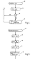
- Fig. 1 eine Prinzipdarstellung der erfindungsgemäßen Anordnung und der zur Durchführung der Steuerung wesentlichen Programm- bzw. Schaltungsblöcke und
- Fig. 2 - 8 die Flussdiagramme für die Steuerung nach Fig. 1.
- Fig. 1 is a schematic diagram of the arrangement according to the invention and the program or circuit blocks essential for carrying out the control and
- FIGS. 2-8 are the flowcharts for the controller of FIG. 1.
Die Anordnung weist einen Rollladen 1 auf, der über eine Antriebseinrichtung 2 wahlweise in Gang zu setzen ist. Die Steuerung der Antriebseinrichtung 2 erfolgt mit Hilfe einer Steuereinrichtung 3.The arrangement has a
Zu dem Rollladen 1 gehört eine Wickelwelle 4, die beidends über Zapfen 5 und 6 in einem nicht veranschaulichten Rollladenkasten drehbar gelagert ist. An der Wickelwelle 4 ist mit einer Kante ein Rollladenvorhang 7 befestigt, der aus mehreren parallel zueinander verlaufenden Rollladenlamellen 8 besteht, die über eine Nut-und-Federverbindung miteinander gekoppelt sind. Seine untere Kante ist von einer Abschlussleiste 9 gebildet, an der zwei Anschläge 11 starr befestigt sind. Die Anschläge 11 in Gestalt von zylindrischen Zapfen können sich an den Rand des Schlitzes des nicht gezeigten Rollladenkastens anlegen, um zu verhindern, dass der Rollladenvorhang 7 vollständig im Rollladenkasten verschwindet. Sie wirken insoweit zusammen mit dem Schlitz des Rollladenkastens als mechanischer Endanschlag.To the
Neben einem Stirnende der Wickelwelle 4 ist eine Gurtscheibe 12 angeordnet, die mit der Wickelwelle 4 drehfest verbunden ist. Auf der Gurtscheibe 12 ist ein Zuggurt 13 aufwickelbar, der mit einem Ende auf der Gurtscheibe 12 festgelegt ist. Die Gurtscheibe 12 ist, wie bei Roll-Läden üblich, eine Bordscheibe, um ein seitliches Herunterlaufen des Zuggurtes 13 zu verhindern. Der Zuggurt 13 ist in seinem unteren Ende in Fig. 1 in Gestalt einer gestrichelten Linie symbolisch veranschaulicht.In addition to a front end of the winding shaft 4, a
Die Antriebseinrichtung 2, die am unteren Ende mit dem Zuggurt 13 zusammenwirkt ist stark schematisiert und außerdem um 90° gedreht gezeigt, um den Verlauf des Zuggurtes 13 veranschaulichen zu können.The drive device 2, which interacts with the
Zu der Antriebseinrichtung 2 gehören eine erste Friktionsrolle 14, die über einen permanent erregten Gleichstrommotor 15 mit Untersetzungsgetriebe angetrieben ist, zwei weitere Friktionsrollen 16 und 17, die über nicht veranschaulichte Stirnzahnräder mit der Friktionsrolle 14 drehfest verbunden und zu dieser achsparallel sind, sowie eine in der Wand des betreffenden Gebäudes untergebrachte Aufwickelautomatik 18 mit einer Gurtscheibe 19, die mittels einer symbolisch angedeuteten Feder 21 im Aufwickelsinne des Zuggurtes 13 vorgespannt ist.To the drive means 2 include a
Zwischen den Friktionsrollen 14, 16 und 17 läuft der Zuggurt 13, wie veranschaulicht, mäanderförmig hindurch, wobei wenigstens eine der Rollen omegaförmig umschlungen ist.Between the
Das untere Ende des Zuggurtes 13 ist auf der Scheibe 19 befestigt, damit mit Hilfe der Feder 21, die als Federmotor wirkt, der Abschnitt des Zuggurtes 13 zwischen der Friktionsrolle 17 und der Aufwickelscheibe 19 gespannt gehalten wird.The lower end of the
Der Motor 15 sowie die Friktionsrollen 14, 16 und 17 sind gemeinsam in einer nicht veranschaulichten Platine angeordnet bzw. gelagert. In dieser Platine ist ferner eine Tastrolle 22 drehbar gelagert, und zwar um eine Achse, die zu den Achsen der Friktionsrollen 14, 16 und 17 sowie der Aufwickelscheibe 19 achsparallel ist. Die Tastrolle 22 ist so angeordnet, dass der gespannte Zuggurt 13 über deren Umfangsfläche läuft und die Tastrolle 22 durch Reibschluß mitnehmen kann.The
Mit der Tastrolle 22 ist eine Scheibe 23 drehfest gekuppelt, die durch einen Sensor 24 abgetastet wird. Der Sensor 24 kann ein optischer oder ein Magnetfeldsensor sein, der Unregelmäßigkeiten an der Scheibe 23 abtastet und bei jedem Durchgang einer Ungleichmäßigkeit über eine Anschlussleitung 25 einen elektrischen Impuls abgibt. Die Zahl der abgegebenen Impulse ist der von dem Zuggurt 13 zurückgelegten Strecke proportional.With the
Den Kern der Steuerungseinrichtung 3 bildet ein Mikrocontroller oder Mikroprozessor 26, der über mehrere Eingänge 27, 28, 29, 31 und 32 sowie einen Steuerausgang 33 verfügt. Anstelle des Mikrocontrollers 26 kann auch ein ASIC verwendet werden, das entsprechend dem nachfolgend erläuterten Programm hardwaremäßig konfiguriert bzw. verdrahtet ist.The core of the
An den Eingang 32 ist die Leitung 25 angeschlossen, über die dem Mikrocontroller 26 Impulse zugeführt werden, solange sich die Tastrolle 22 dreht, was gleichbedeutend ist mit einer Bewegung des Zuggurtes 13. In dem Mikrocontroller werden die Impulse mittels eines Zählers fortwährend gezählt und liefern so eine Information über die Stellung des Rolladenvorhangs 7. Der Zähler ist ein Vorwärts-/Rückwärtszähler, der auch das Vorzeichen berücksichtigt. Er zählt z.B. vorwärts, wenn sich der Rollladenvorhang 7 nach oben bewegt, und rückwärts, wenn sich der Rollladenvorhang nach unten bewegt. Der maximale Zählumfang ausgehend von 0 ist nach beiden Richtungen größer als die maximal zu erwartende Anzahl von Impulsen, wenn der Rollladenvorhang 7 seinen vollen Hub durchläuft. Auf diese Weise gibt es keinen Überlauf, wenn der Zähler zurückgesetzt wird, wenn sich der Rollladenvorhang 7 in einer seiner physikalisch möglichen Grenzlagen befindet.At the
An die Eingänge 27, 28 und 29 sind über entsprechende Leitungen drei Tastschalter 34, 35 und 36 angeschlossen, deren anderer Kontakt, wie der nach oben gerichtete Pfeil zeigt, mit der positiven Versorgungsspannung verbunden ist. Die beiden Tastschalter 34 und 35 dienen als Laufrichtungstaster, während der Tastschalter 36 ein Set- oder Programmierschalter ist.To the
Der Ausgang 33 liegt an einer symbolisch angedeuteten Relaisschaltergruppe 37, über die die elektrische Verbindung von einer Versorgungsspannung 38 zu dem Motor 15 und von dem Motor 15 über einen Stromfühlerwiderstand 39 zur Schaltungsmasse 41 herstellbar ist. Die Relaisschaltergruppe 37 dient gleichzeitig als Umpolschalter für den Motor 15, womit insgesamt drei Zustände wenigstens möglich sind, nämlich ein Ausschaltzustand, in dem der Motor 15 keinen Strom bekommt und am Eingang kurzgeschlossen ist, sowie zwei Einschaltzustände, in denen er mit der einen oder der anderen Polarität zwischen der Stromversorgung 38 und der Schaltungsmasse 41 liegt. Es versteht sich, dass der Ausgang 33 gegebenenfalls ein mehrpoliger Ausgang ist, um diese mehreren Schaltzustände der Relaisschaltergruppe 37 zu ermöglichen.The
Der Eingang 31 ist schließlich mit dem heißen Ende des Stromfühlerwiderstands 39 verbunden, um den Spannungsabfall an dem Stromfühlerwiderstand 39 zu messen. Der Spannungsabfall dient als Kriterium für die physikalische Grenzlage des Rollladenvorhangs 7. Um den Spannungsabfall zu erfassen enthält der Mikrocontroller einen Spannugsdiskriminator, der den Spannungsbfall mit einem intern vorgebbaren Schwellwert vergleicht und abhängig von dem Vergleich ein entsprechendes Binärsignal zur Verfügung stellt. Der Diskriminator kann auch außerhalb des Mikrocontrollers verwirklicht sein.The
In dem Mikrocontroller bzw. in dessen in ihm realisierten Speicher ist ein Programm enthalten, dessen Ablaufschema in den nachfolgenden Figuren wiedergegeben ist.In the microcontroller or in his realized in him memory a program is included, the flow chart is shown in the following figures.
Mit dem Einschalten der Stromversorgung wird der Mikroprozessor 26 auf der konstruktionsmäßig festgelegten Startadresse gestartet und wickelt zunächst bei 51 ein Programm ab, durch das die Register normiert und bestimmte Speichervariablen auf einen für den Programmlauf erforderlichen Anfangswert gesetzt werden. Hierzu gehört auch die Voreinstellung des internen Zählers, der die Impulse an dem Eingang 32 zählt. Der Zähler wird z.B. auf "null" gesetzt.Upon power up, the microprocessor 26 is started at the designated start address and initially unwraps a program at 51 which normalizes the registers and sets certain memory variables to an initial value required for the run. This includes the presetting of the internal counter, which counts the pulses at the
Nach dem Reset des Prozessors fährt das Programm fort und fragt bei 52 ab, ob die Laufrichtungstaste 34, mit der das Öffnen des Rollladens 1 angeordnet wird, betätigt ist. Falls ja, geht das Programm unmittelbar zu dem Anfang des Abfrageblocks 52 zurück. Hierdurch soll verhindert werden, dass versehentlich unmittelbar nach dem Einschalten der Stromversorgung oder einer Spannungswiederkehr der Rollladen 1 in einer Richtung in Bewegung gesetzt wird. Falls die Laufrichtungstaste 34 nicht betätigt ist, gelangt das Programm in einen zweiten Abfrageblock 53, in dem das Programm prüft, ob die andere Laufrichtungstaste 35, mit der das Schließen des Rollladens 1 angefordert wird, betätigt ist. Falls ja, läuft das Programm zum Anfang des Abfrageblocks 53 und nur im Fall, dass keine Taste betätigt ist, fährt das Programm mit einem nächsten Anweisungsblock 54 fort. Der Abfrageblock 53 hat dieselbe Aufgabe wie der Abfrageblock 52, nämlich ein fehlerhaftes oder ungewolltes Ingangsetzen des Rollladens 1 zu verhindern.After the processor is reset, the program proceeds and queries 52 whether the running direction key 34, with which the opening of the
Wenn beide Tasten nicht gedrückt sind, wird der Anweisungsblock 54 ausgeführt, in dem mehrere Variable, eine Variable MSA, eine Variable MSE, eine Variable MP zurückgesetzt sowie ein Kurzzeitzähler (Stoppuhr) SZ geladen wird. Außerdem kann an dieser Stelle eine an den Mikroprozessor optional angeschlossene Anzeige 55 ausgeschaltet werden. Diese Leuchtdiode 55 signalisiert dem Benutzer, dass die Steuerungseinrichtung 3 im Sinne der Festlegung einer benutzerdefinierten Endlage programmierbar ist.If both keys are not pressed, the
Die Variablen MSA und MSE werden dazu verwendet, nach einer Betätigung der Settaste 36 deren Loslassen zu erkennen und erst ab diesem Zeitpunkt die "Stoppuhr" zu starten. Insofern dienen die Variablen dazu, eine negative Flankentriggerung zu verwirklichen, wie sich dies aus der nachfolgenden Beschreibung ergibt.The variables MSA and MSE are used to detect their release after an actuation of the settable 36 and to start the "stopwatch" only from this point in time. In this respect, the variables serve to realize a negative edge triggering, as is clear from the following description.
Nachdem der Anweisungsblock 54 durchlaufen ist, wird ein Abfrageblock 56 ausgeführt, in dem das Programm prüft, ob die Laufrichtungstaste 34 betätigt ist. Wenn ja, wird ein Unterprogramm 57 gestartet, das ein Öffnen des Rollladens 1 veranlasst. Ist die Taste 34 nicht betätigt, fährt das Programm mit einem Abfrageblock 59 fort, in dem die Taste 35 überprüft wird. Falls sie betätigt ist, wünscht der Benutzer ein Schließen des Rollladens 1, weshalb das Programm bei 58 in das entsprechende Unterprogramm wechselt. Liegt keine Betätigung vor, so schließt sich an den Abfrageblock 59 ein Abfrageblock 61 an, in dem geprüft wird, ob die Variable MSE gesetzt ist. Falls nein, prüft das Programm bei 62, ob der Benutzer die Settaste 36 betätigt hält. Ist auch dies nicht der Fall, so kehrt das Programm an den Eingang des Abfrageblocks 56 zurück. Ist hingegen die Taste 36 im betätigten Zustand, wird ein Anweisungsblock 63 ausgeführt. In diesem Anweisungsblock 63 werden die Variablen MSE und MP gesetzt und außerdem wird die Leuchtdiode 55 eingeschaltet. Anschließend kehrt das Programm zu dem Eingang des Abfrageblocks 56 zurück.After the
Für den nächsten Durchlauf sei angenommen, dass die Variable MSE tatsächlich gesetzt ist, womit das Programm an dem Abfrageblock 61 zu dem Eingang eines Abfrageblocks 64 verzweigt, in dem geprüft wird, ob zusätzlich auch die Variable MSA gesetzt ist. Falls ja, erfolgt in einem Abfrageblock 65 die Prüfung, ob sich die Settaste 36 im betätigten Zustand befindet. Wenn nein, ist das ein Zeichen dafür, dass der Benutzer die Settaste 36 losgelassen hat, womit die durch die Variable SZ gebildete Stoppuhr zu laufen beginnt, damit das Programmieren einer Endlage nur für eine vorbestimmte Zeit möglich ist, um Fehlbedienungen auszuschließen. Diese Zeit wird durch die Laufzeit der durch die Variablen SZ definierten Stoppuhr realisiert, die demzufolge in einem Anweisungsblock 66 dekrementiert wird, und durch die Leuchtdiode 55 angezeigt.For the next pass, assume that the variable MSE is actually set, thus branching the program at the
Falls die Variable SZ noch nicht wieder auf null zurückgegangen ist, was in einem Abfrageblock 67 überprüft wird, kehrt das Programm zu dem Anfang des Abfrageblocks 56 zurück. Falls hingegen die Variable SZ bis auf null dekrementiert wurde, ist die "Stoppuhr" abgelaufen und es ist kein Programmieren der Endlage durch die Laufrichtungstasten 34, 35 mehr möglich, solange bis erneut die Settaste 36 betätigt ist. Die Laufrichtungstasten 34, 35 dienen dann nur noch dazu, den Rollladen 1 nach oben oder unten in Gang zu setzen, was dem Normalbetrieb entspricht. Das Programm kehrt deswegen für den Fall, dass SZ zu null geworden ist, an den Eingang des Anweisungsblocks 52 zurück. Die Setzeit ist abgelaufen und muß gegebenfalls neu gestartet werden.If the variable SZ has not yet returned to zero, which is checked in a
Für den Fall, dass die Prüfung in dem Abfrageblock 64 ergeben hat, dass die Variable MSA nicht gesetzt ist, erfolgt die weitere Abfrage, ob sich die Settaste 36 noch im betätigten Zustand befindet. Diese Überprüfung erfolgt in einem Abfrageblock 68. Hat der Benutzer die Settaste 36 losgelassen, d.h. sie befindet sich im Zustand mit geöffnetem Schalter, wird anschließend in dem Anweisungsblock 69 die Variable MSA gesetzt, ehe das Programm am Ausgang des Anweisungsblocks 69 zu dem Eingang des Abfrageblocks 56 zurückkehrt.In the event that the check in the
Hält hingegen der Benutzer die Settaste 36 nach wie vor gedrückt, so wird der Anweisungsblock 69 übersprungen. Mit Hilfe der Blöcke 56 bis 69 wird erreicht, dass eine nachfolgend beschriebene Programmierung von willkürlich zu definierenden Endlagen erst möglich ist ab dem Zeitpunkt, nachdem der Benutzer die Settaste 36 losgelassen hat. Mit dem Loslassen der Settaste 36 beginnt eine Zeit zu laufen, innerhalb der er den Vorgang zum Programmieren der Endlage gestartet haben muss, indem er entweder die Laufrichtungstaste 34 zum Festlegen einer oberen Endlage oder die Laufrichtungstaste 35 zum Definieren einer unteren gewillkürten Endlage betätigt haben muss. Nach dem Ablauf dieser Zeit ist eine Veränderung oder Einstellung der gewillkürten Endlagen nicht mehr möglich bis zum erneuten Betätigen der Settaste 36. Die Laufrichtungstasten 34, 35 dienen wie bereits erwähnt dann nur noch dazu, den Rollladen 1 nach oben oder unten in Gang zu setzen, was dem Normalbetrieb entspricht.If, on the other hand, the user continues to hold the settest key 36, the
Wie Fig. 2 erkennen lässt, kann der Benutzer unabhängig von der Betätigung der Settaste 36 Fahrbefehle mit Hilfe der Laufrichtungstasten 34 oder 35 anweisen und ausführen lassen.As shown in FIG. 2 reveals, regardless of the operation of the settable 36, the user can instruct and carry running commands by means of the
Hat der Benutzer die Laufrichtungstaste 34 betätigt und der Prozessor dies im Abfrageblock 56 erkannt, verzweigt das Programm in das Unterprogramm zum Öffnen des Rollladens 1, wie es in Fig. 3 gezeigt ist. In diesem Programmabschnitt wird zunächst überprüft, ob die aktuelle Position der oberen Endlage entspricht. Dies geschieht durch Vergleich des Zählerinhalts des oben erwähnten Impulszählers mit einem gespeicherten Wert, der dem Zählerinhalt an der jeweiligen Endlage entspricht; es handelt sich dabei um die weiter unten noch erklärten Variablen "obere Grenze" bzw. "maximale Grenzlage oben". Dieser Zähler bekommt seine Zählimpulse über den Eingang 32 von dem Impulsgeber, der durch die Codierscheibe 23 und den Sensor 24 gebildet ist. Dieser Impulsgeber liefert solange Impulse, wie sich der Zuggurt 13 bewegt, wobei die Anzahl der Impulse der Wegstrecke proportional ist, die der Zuggurt 13 zurücklegt.If the user has actuated the running direction key 34 and the processor recognizes this in the
Die Prüfung erfolgt in einem Abfrageblock 71. Falls die obere Grenzlage bereits erreicht ist, wird das Unterprogramm sofort verlassen, und zwar zum Eingang des Anfrageblocks 52. Falls die obere Endposition noch nicht erreicht ist, wird in einem Anweisungsblock 73 dafür gesorgt, dass über den Ausgang 33 an den Relaisschaltersatz 37 Signale abgegeben werden, damit der Motor 15 für die entsprechende Drehrichtung mit der Versorgungsspannung 38 verbunden wird. Anschließend wird in einem Anweisungsblock 74 eine Warteschleife gestartet, ehe das Programm von dort zu einem Abfrageblock 75 fortfährt.The check takes place in a
In dem Abfrageblock 75 wird geprüft, ob der Strom durch den Sensorwiderstand 39, d.h. der Spannungsabfall über den Sensorwiderstand 39 oberhalb oder unterhalb eines vorbestimmten Grenzwertes liegt.In the
Das Übersteigen des Grenzwertes entsteht, wenn das dem Motor abgeforderte Drehmoment einen entsprechenden Grenzwert überschreitet. Dies ist in der Regel dann der Fall, wenn die Anschläge 11 an dem Schlitz des Rollladenkastens zur Anlage kommen, was wiederum mit der maximal möglichen oberen Grenzlage des Rollladens 1 gleichzusetzen ist. Insoweit dient der Stromfühlerwiderstand 39 zusammen mit dem in dem Mikrocontroller 26 realisierten Diskriminator als Erkennungseinrichtung für die obere physikalisch mögliche Grenzlage.The exceeding of the limit value arises when the torque requested by the motor exceeds a corresponding limit value. This is usually the case when the
Da beim Anlaufen möglicherweise der Motor einen höheren Strom zieht, der über der vorher festgelegten Schwelle liegt, erfolgt die Abprüfung in dem Abfrageblock 75 nicht unmittelbar im Anschluss an den Anweisungsblock 73, sondern durch den Anweisungsblock 74 zeitverzögert.Since, at start-up, the motor may pull a higher current than the predetermined threshold, the check in the
Falls die obere Grenzlage erreicht ist, was durch Überschreiten des Grenzwertes angezeigt wird, verzweigt das Programm zu dem Unterprogramm "Endabschalten oben". Wenn nein, ist die Schwelle für den maximal zulässigen Spannungsabfall über den Sensorwiderstand 39 nicht erreicht, und es prüft das Programm in einem Abfrageblock 77, ob eine Hilfsvariable MAUF gesetzt ist.If the upper limit position is reached, which is indicated by exceeding the limit value, this branches Program for the subroutine "Endabschalten oben". If not, the threshold for the maximum allowable voltage drop across the
Die Variable MAUF dient als Flipflop und soll dafür sorgen, dass der Rollladen 1 im Sinne des Öffnens weiterläuft, auch dann, wenn der Benutzer die betreffende Laufrichtungstaste 34 bereits losgelassen hat. Um dies zu erreichen, wird bei dem vorliegenden Ablaufdiagramm die Variable MAUF nach dem Loslassen der Laufrichtungstaste 34 gesetzt und durch ein erneutes Betätigen wieder zurückgesetzt. Demzufolge ist beim ersten Durchlauf durch den Programmteil nach Fig. 3 die Variable MAUF nicht gesetzt und das Programm fährt nach dem Abfrageblock 77 mit einem weiteren Abfrageblock 78 fort, in dem der Zustand der Laufrichtungstaste 34 überprüft wird. Befindet sie sich nicht mehr im betätigten Zustand, wird nach dem Abfrageblock 78 in dem Anweisungsblock 79 die Variable MAUF gesetzt, im anderen Falle wird der Anweisungsblock 79 übersprungen.The variable MAUF serves as a flip-flop and is intended to ensure that the
Sodann wird nachfolgend in einem Abfrageblock 81 untersucht, ob die aktuelle Position größer ist als eine vorher definierte obere Position. Falls nein, fährt das Programm mit dem Abfrageblock 75 fort, andernfalls wechselt das Programm zu einem Unterprogramm 81 "Abschalten oben".Next, it is examined in a
Da der Schleifendurchlauf verhältnismäßig schnell erfolgt und auch dieser Programmabschnitt gemäß Fig. 3 nur angesprungen wird, wenn wenigstens kurzzeitig die Laufrichtungstaste 34 betätigt ist, wird zunächst während der ersten Durchläufe die Variable MAUF zurückgesetzt bleiben, weshalb der Durchlauf wie oben beschrieben erfolgt. Bei einem der Schleifendurchläufe wird der Benutzer die Laufrichtungstaste 34 loslassen, so dass am Abfrageblock 78 die Bedingung erfüllt ist und die Variable MAUF im Anweisungsblock 79 gesetzt wird. Damit wird bei den nächsten Durchläufen im Abfrageblock 77 die Bedingung erfüllt sein und das Programm künftig über einen Abfrageblock 83 fortfahren, in dem geprüft wird, ob zwischenzeitlich erneut die Laufrichtungstaste 34 gedrückt wird. Falls nein, wechselt das Programm zu dem Eingang des Abfrageblocks 81, falls ja, wird dies als Befehl verstanden, die Bewegung des Rollladenvorhangs zu stoppen. Dementsprechend fährt das Programm über einen Anweisungsblock 84 fort, in dem die Variable MAUF für den nächsten Lauf zurückgesetzt wird. Nach Ausführung des Anweisungsblocks 84 geht das Programm in das Unterprogramm "Abschalten oben".Since the loop pass is relatively fast and also this program section shown in FIG. 3 is only jumped when at least briefly the running direction key 34 is actuated, the variable MAUF will initially remain reset during the first passes, why the run is done as described above. On one of the loop passes, the user will release the run direction key 34 so that at
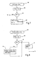
Das Programm "Abschalten oben" ist in Fig. 4 gezeigt.The program "Shut Down Above" is shown in FIG.
Die erste Funktion, die in dem Programmteil 82 "Abschalten oben" durchgeführt wird, geschieht in einem Anweisungsblock 85, durch den an dem Ausgang 33 ein Signal erzeugt wird, so dass der Relaisschalterblock 37 die Stromversorgung zu dem Motor 15 unterbricht. Daran anschließend wird in einem Abfrageblock 86 überprüft, ob die Variable MP gesetzt ist. Diese Variable MP wurde gegebenenfalls in dem Anweisungsblock 63 (Fig. 2) gesetzt, wenn der Benutzer die Settaste 36 gedrückt hatte.The first function, which is performed in
Mit dem Drücken der Settaste 36 zeigt der Benutzer der Steuerungseinrichtung 3 seinen Wunsch an, dass die durch das vorausgehende Betätigen der Laufrichtungstaste 34 erreichte obere Endposition als künftige gewillkürte obere Endposition benutzt wird, die fortan beim Öffnen des Rollladenvorhangs 7 nicht mehr überfahren wird. Wenn also die Variable MP gesetzt ist, wechselt das Programm zu einem Anweisungsblock 87.With the pressing of the
In diesem Anweisungsblock 87 wird die Variable "obere Grenze" auf den Zählinhalt des Zählers gesetzt und außerdem wird die Variable MP gelöscht. Sodann kehrt das Programm an den Anfang des Anweisungsblocks 52 zurück und wartet auf die nächste Befehlseingabe durch Betätigen einer der Tasten 34 bis 36. Während des Wartevorgangs wird ständig der Hauptast über die Abfrageblöcke 56, 59 und 62 durchlaufen.In this
Für den Fall, dass die Variable MP nicht gesetzt war, geht das Programm nach dem Abfrageblock 86 ebenfalls zu dem Eingang des Anweisungsblocks 52 zurück und wartet, wie vorstehend erwähnt. Bei nichtgesetzter Variabler MP wird der Anweisungsblock 87 nicht ausgeführt.In the event that the variable MP was not set, the program also returns to the input of the
Im Zusammenhang mit der Erläuterung der Fig. 3 wurde bereits beschrieben, dass die Rollladensteuerung 3 erkennt, wann der Rollladenvorhang 7 seine obere physikalische Grenzlage erreicht. Diese Erkennung geschieht in dem Abfrageblock 75, wobei, wenn die Bedingung erfüllt ist, in das Programmteil 76 "Endabschalten oben" gewechselt wird. Dieser Programmteil ist in Fig. 5 schematisch gezeigt. Auch in dem Programmteil 76 "Endabschalten oben" wird zunächst in einem Anweisungsblock 88 der Motor ausgeschaltet.In connection with the explanation of FIG. 3 has already been described that the
Da in diesem Zustand der Rollladenvorhang 7 unter einer erheblichen Spannung steht, weil die an ihm befestigten Anschläge 11 am Rollladenkasten anliegen, wird zunächst in einem weiteren Schritt die Spannung gemindert, in dem in einem Anweisungsblock 89 über den Ausgang 33 ein elektrisches Signal an die Relaisschaltergruppe 37 abgegeben wird, das dafür sorgt, dass der Motor 15 in der umgekehrten Richtung im Sinne des Absenkens des Rollladenvorhangs 7 in Bewegung gesetzt wird. Diese Absenkbewegung ist entweder zeitgesteuert oder sie wird über den Zähler gesteuert und angehalten, sobald der Zähler eine vorbestimmte Anzahl von Schritten, ausgehend von dem Zählerstand, zurückgezählt hat, bei dem die Bedingung in dem Abfrageblock 75 erreicht war, d.h. die Stromgrenze überschritten war. Sodann wird in einem Anweisungsblock 91 der Motor ausgeschaltet.Since in this state the roller shutter curtain 7 is under considerable tension, because the
Anschließend wird die Variable "maximale Endlage oben" in einem Anweisungsblock 92 mit dem aktuellen Zählerstand besetzt. Diese Variable "maximale Endlage oben" wird künftig, wie bereits erwähnt, in dem Abfrageblock 81 ausgewertet, so dass fortan bis zum nächsten Löschen sämtlicher Variablen, beispielsweise durch Spannungsausfall, das Programmstück 76 "Endabschalten oben" nicht mehr erreicht wird.Subsequently, the variable "maximum end position above" is occupied in a
Ersichtlicherweise benötigt das Programm keine absolute obere Grenze, sondern die Steuerungseinrichtung 3 sucht sich die obere Grenzlage selbst, wobei der Zählerinhalt zwar die Position wiedergibt, jedoch nicht auf eine bestimmte Lage des Rollladenvorhangs 7 zu Beginn des Programmlaufes fixiert ist. Das System arbeitet gleichsam mit einem "schwimmenden Nullpunkt" und sucht sich die obere Endlage selbst. Diese obere Endlage wird dann mit einem Zählerinhalt gleichgesetzt, der sich in zufälliger Weise aus den Anfangsbedingungen ergibt, dann jedoch solange gleich bleibt, bis das System aufgrund eines Stromausfalls sein Gedächtnis verloren hat.Evidently, the program does not require an absolute upper limit, but the
Nach dem Verlassen des Anweisungsblocks 92 kehrt das Programm zu dem Anfang des Anweisungsblocks 52 zurück.After exiting the
Fig. 6 zeigt das Programmstück 58 "Rollladen schließen". Es beginnt damit, in einem Abfrageblock 93 zu prüfen, ob der Inhalt des Zählers kleiner geworden ist als der Inhalt einer Variablen "untere Grenze". Diese Variable entspricht sinngemäß der Variablen "obere Grenze", lediglich mit dem Unterschied, dass es sich hierbei um die gewillkürte untere Endlage handelt. Die Art und Weise, wie diese Variable gewonnen wird, wird noch weiter unten erläutert.Fig. 6 shows the
Ist die gewillkürte untere Endlage erreicht, kehrt das Programm umgehend zu dem Eingang des Anweisungsblocks 52 zurück. Andernfalls wird der Motor in einem Anweisungsblock 94 im Sinne des Ablassens des Rollladenvorhangs 7 über den Ausgang 33 eingeschaltet.When the arbitrary lower limit position is reached, the program immediately returns to the input of the
Die physikalisch mögliche untere Grenzlage wird durch Ausbleiben von Impulsen der Tastrolle 22 erkannt. Hierzu ist es notwendig, in dem Programm eine Kurzzeituhr vorzusehen, mit deren Hilfe ein retriggerbares Monoflop simuliert wird, das jedesmal zurückgesetzt wird, wenn von dem Sensor 24 ein Impuls ankommt. Bleiben diese Impulse aus, wird das Monoflop nicht mehr zurückgesetzt und damit erkannt, dass der Rollladenvorhang 7 vollständig abgelassen ist oder sonstwie unten mit seiner Unterkante aufsteht.The physically possible lower limit position is detected by the absence of pulses of the
Um diesen Monoflop zu realisieren, wird im Anschluss an den Anweisungsblock 94 in einem Anweisungsblock 95 eine Variable "Uhr" geladen, die bei jedem nachfolgend beschriebenen Schleifendurchlauf dekrementiert wird. Da der Zeitbedarf für den Schleifendurchlauf bekannt ist, ist eine bestimmte Zeit abgelaufen, wenn die Variable "Uhr" auf null zurückgezählt ist. Außerdem wird in dem Anweisungsblock 95 der aktuelle Zählerstand zwischengespeichert.In order to realize this monoflop, following the
Auch im Programm "Rollladen schließen" gibt es eine Variable, die der Variablen MAUF funktionsmäßig entspricht, um einen Dauerlauf bis zur erneuten Betätigung einer Taste zu erreichen. Diese Variable wird zur Unterscheidung MAB genannt und ist beim Einstieg in den Programmabschnitt nicht gesetzt. Sie wird in einem Abfrageblock 96 abgeprüft, der auf den Anweisungsblock 95 folgt. Weil die Variable MAB nicht gesetzt ist, wird nach dem Abfrageblock 96 der Abfrageblock 97 ausgeführt, in dem die Taste 35 abgefragt wird. Ist sie zwischenzeitlich nicht mehr betätigt, wird in einem Anweisungsblock 98 MAB gesetzt oder, falls der Benutzer die Taste 35 nach wie vor gedrückt hält, wird der Anweisungsblock 98 übersprungen.There is also a variable in the "Shut down shutter" program that corresponds functionally to the variable MAUF in order to achieve continuous operation until a key is pressed again. This variable is called MAB for differentiation and is not set when entering the program section. It is checked in a
In jedem Fall wird am Ausgang des Anweisungsblocks 98 in einem Abfrageblock 99 geprüft, ob der Zählerstand gleich dem Inhalt der Variablen "minimale Endlage unten" oder der Variablen "untere Grenze" geworden ist. Wenn ja, ist dies das Zeichen dafür, dass der Rollladenvorhang 7 nicht mehr weiter abgesenkt werden kann oder soll. Dementsprechend wechselt das Programm hier in einen Programmteil 100 "Abschalten unten".In any case, at the output of the
Wenn die untere Endlage nicht erreicht ist, wird in einem Abfrageblock 101 die Variable "Uhr" dekrementiert und überprüft, ob sie auf null zurückgelaufen ist. Falls dies nicht der Fall ist, geht das Programm zu dem Eingang des Abfrageblocks 96 zurück. Andernfalls, d.h. bei abgelaufener Uhr, wird in einem Abfrageblock 102 untersucht, ob der Zählerinhalt sich von dem Zählerinhalt unterscheidet, der in dem Anweisungsblock 95 zwischengespeichert war. Im Falle eines Unterschiedes zwischen diesen beiden Werten sind nach wie vor Impulse von der Tastrolle 22 gekommen. Sind hingegen die Inhalte gleich, ist die Tastrolle 22 mittlerweile stehen geblieben, weil der Zuggurt 13 von der Tastrolle 22 abgehoben hat. Der Rollladenvorhang 7 steht folglich auf, weshalb mit einem Programmteil 103 "Endabschaltung unten" fortgefahren wird. Waren hingegen noch Impulse angekommen, kann die Absenkbewegung fortgeführt werden, weshalb das Programm bei weiter ankommenden Impulsen nach dem Abfrageblock 102 zu dem Anfang des Anweisungsblocks 95 zurückkehrt, in dem die Uhr neu gesetzt wird und auch der Zählerstand erneut zwischengespeichert wird.If the bottom limit is not reached, in a
Nach einigen Schleifendurchläufen wird die Variable MAB gesetzt sein mit der Folge, dass nach dem Abfrageblock 95 nicht mehr mit dem Abfrageblock 96 fortgefahren wird, sondern zu einem Abfrageblock 104 verzweigt wird. In diesem Abfrageblock 104 wird der Zustand der Laufrichtungstaste 35 überprüft. Wird sie erneut betätigt, so muss der Rollladenvorhang 7 angehalten werden. Ist die Taste 35 hingegen nicht betätigt, wird der Lauf des Rollladenvorhangs 7 fortgesetzt und das Programm wechselt zu dem Eingang des Abfrageblocks 99. Andernfalls, d.h. bei betätigter Laufrichtungstaste 35, wird in einem Anweisungsblock 105 die Variable MAB zurückgesetzt und das Programm in Richtung auf den Programmteil 100 "Abschalten unten" verlassen.After some loop iterations, the variable MAB will be set, with the result that after
Der Programmteil 100 "Abschalten unten", wie er in Fig. 7 gezeigt ist, entspricht sinngemäß dem Programmteil "Abschalten oben" gemäß Fig. 4.The
Der Programmteil 100 "Abschalten unten" beginnt damit, dass in einem nachfolgenden Anweisungsblock 106 der Motor ausgeschaltet wird. Daran anschließend wird in einem Anweisungsblock 107 überprüft, ob der Benutzer eine willkürlich untere Endlage programmieren wollte, was dann das Programm anhand des Zustands der Variablen MP, wie bereits oben erwähnt, prüft. Wenn die Variable MP nicht gesetzt ist, geht das Programm unmittelbar zu dem Eingang des Anweisungsblocks 52 zurück. Andernfalls wird in einem Anweisungsblock 108 eine Variable "untere Grenze" mit dem Wert des aktuellen Zählerinhaltes besetzt und die Variable MP gelöscht.The
Bei künftigen Fahrbewegungen des Rollladenvorhangs 7 im Sinne des Absenkens wird der Rollladenvorhang 7 immer an einer Stelle angehalten, bei der der Zählerstand gleich dieser gespeicherten Variablen "untere Grenze" ist.In future driving movements of the shutter curtain 7 in the sense of lowering the shutter curtain 7 is always stopped at a point at which the count is equal to these stored variables "lower limit".
Schließlich ist noch der Fall zu berücksichtigen, dass der Rollladenvorhang 7 unten an der Fensterbegrenzung aufstößt, was im Abfrageblock 102 gemäß Fig. 6 festgestellt wurde. Das Programm verzweigt in diesem Falle den Programmteil 103, wie er in Fig. 8 gezeigt ist. Dieser Programmteil 103 entspricht weitgehend dem Programmteil gemäß Fig. 5, d.h. es wird zunächst in einem Anweisungsblock 109 veranlasst, dass der Motor ausgeschaltet wird.Finally, the case must be taken into account that the roller shutter curtain 7 abuts the bottom of the window boundary, which was found in the
Da davon auszugehen ist, dass der Zähler bis zum Erkennen des Stillstands eine empirisch zu ermittelnde Anzahl von Impulsen "verliert", wird eine Variable "minimale Endlage unten" auf den Inhalt des Zählerstandes abzüglich einem Korrekturwert gebracht.Since it can be assumed that the counter "loses" an empirically determined number of pulses until the standstill is detected, a variable "minimum end position below" is brought to the contents of the counter reading minus a correction value.
Der Verlust an Impulsen entsteht, weil der Zuggurt 13 von der Tastrolle 22 sich abhebt aber noch ein Stück läuft, ehe das System den Stillstand der Tastrolle 22 erkennt. Der Korrekturwert hierfür wird empirisch ermittelt und sorgt dafür, dass beim Öffnen des Rollladens 1 wieder dieselbe obere physikalische Lage des Rollladenvorhangs 7 erreicht wird, wenn der Inhalt des Zählers gleich der Variablen "maximale Endlage oben" geworden ist oder im Falle einer benutzerdefinierten Endlage gleich der Variablen "obere Grenze".The loss of impulses arises because the
Diese Korrektur und Speicherung geschieht in dem Anweisungsblock 110 und anschließend wird in einem Anweisungsblock 111 der Zähler auf den Wert entsprechend der Variablen "minimale Endlage unten" gesetzt, ehe zu dem Beginn des Anweisungsblockes 52 zurückgekehrt wird.This correction and storage is done in the
Im Gegensatz zu der Stromgrenze, die am oberen Ende nur einmal erreicht wird, kann die untere Grenzlage beim Schließen des Rollladens 1 ständig angefahren werden.In contrast to the current limit, which is reached only once at the upper end, the lower limit position when closing the
Wenn dies nicht erwünscht ist, kann durch entsprechende Programmierung die Variable "minimale Endlage unten" auf den aktuellen Zählerstand gesetzt werden und der Motor 15 wird solange in Aufwärtsrichtung bewegt, bis der erste Impuls eintrifft. Dies kann in derselben Weise ermittelt werden, wie dies im Zusammenhang mit dem Abfrageblock 101 bereits erläutert wurde. Sodann wird die Variable "minimale Endlage unten" auf den Wert des aktuellen Zählerstands gesetzt.If this is not desired, by appropriate programming the variable "minimum end position down" can be set to the current count and the
Aus Gründen der Normierung kann es zweckmäßig sein, in der unteren Endlage ständig den Zustand mit entspanntemFor reasons of standardization, it may be appropriate in the lower limit constantly the state with relaxed
Zuggurt 13 anzufahren. Damit sich kein Fehler akkumuliert, wird eine zusätzliche Variable MPU eingeführt, die beim ersten Mal des Anfahrens des spannungslosen Zustands des Zuggurtes 13 gesetzt wird. In diesem Falle arbeitet das Programm wie folgt:To approach the
Nachdem der Motor in dem Anweisungsblock 109 abgeschaltet wurde, wird in dem nachfolgenden Anweisungsblock 112 überprüft, ob eine Variable MPU gesetzt ist. Wenn sie nicht gesetzt ist, ist das ein Zeichen für das erste Auflaufen des Rollladenvorhangs 7 auf ein unteres Hindernis und es wird, wie oben beschrieben, der Zählerstand abgelesen, korrigiert und unter der Variablen "minimale Endlage unten" weggespeichert. Außerdem wird in dem Anweisungsblock 110 die Variable MPU gesetzt.After the motor has been turned off in the
Beim nächsten Durchlaufen dieses Betriebszustandes ist folglich die Variable MPU gesetzt, weshalb dann das Programm direkt in den Anweisungsblock 111 verzweigt. In diesem Programmblock 111 wird wie erwähnt der Zählerstand korrigiert, indem der interne Zähler auf den Wert gesetzt wird, den die Variable "minimale Endlage unten" hat.Consequently, the next time this operating state is passed through, the variable MPU is set, for which reason the program branches directly into the
Aus der Sicht des Benutzers sieht die Bedienung der erfindungsgemäßen Rollladensteuerung 3 wie folgt aus:From the user's point of view, the operation of the
Unmittelbar nach dem Installieren und dem Einschalten der Stromversorgung vollführt der Rollladenvorhang 7 keinerlei Bewegung. Der Rollladenvorhang 7 kann nur durch aktives Eingreifen des Benutzers in Bewegung gesetzt werden, beispielsweise im Sinne eines Öffnens, wenn zum Zeitpunkt der Spannungswiederkehr der Rollladenvorhang 7 geschlossen war. Der Benutzer betätigt hierzu die Laufrichtungstaste 34 "AUF" und der Rollladenvorhang 7 wird sich nach oben in Bewegung setzen, bis die Anschläge 11 am Rollladenkasten zur Anlage kommen. Daraufhin führt die Steuerung eine entsprechende Korrektur durch, so dass künftig nicht mehr der mechanische Anschlag erreicht wird. Irgendwann zu einem späteren Zeitpunkt will der Benutzer den Rollladen 1 schließen, was angewiesen wird, indem er die Laufrichtungstaste 35 "AB" betätigt. Der Rollladen 1 wird sich nach unten in Bewegung setzen, bis er mit seiner Unterkante auf irgendwelchen Anschlägen aufsteht und sich der Zuggurt 13 entspannt. Beim erneuten Öffnen durch Betätigen der Laufrichtungstaste 34 bewegt sich der Rollladenvorhang 7 in die zuvor ermittelte obere Endlage, in der die Anschläge 11 gerade eben noch nicht an dem Rollladenkasten anstoßen.Immediately after installing and switching on the power supply performs the blinds curtain 7 no movement. The roller shutter curtain 7 can be set in motion only by active intervention of the user, for example in the sense of opening, if at the time of voltage recovery of the shutter curtain 7 was closed. The user actuates the running direction key 34 for this purpose "OPEN" and the shutter curtain 7 will move upwards until the
Unabhängig von dieser bei der ersten Fahrt durchgeführten Justierung kann der Benutzer jederzeit willkürlich dazwischen liegende Endpositionen programmieren, indem er zunächst die Settaste 36 betätigt und dann innerhalb des zur Verfügung stehenden Zeitfensters, was durch das Leuchten der Leuchtdiode 55 angezeigt wird, den Rollladen 1 über die Laufrichtungstaste 34 oder 35 entweder nach oben oder nach unten in Bewegung setzt und durch erneutes Betätigen derselben Taste wieder anhalten. Diese dann erreichte Lage ist die Endlage, die künftig der Rollladenvorhang 7 einnehmen wird, wenn entweder die Laufrichtungstaste "AUF" oder die Laufrichtungstaste "AB" betätigt wird, ohne dass der Benutzer zuvor durch erneutes Betätigen derselben Taste die Bewegung stoppt.Regardless of this performed during the first trip adjustment, the user can arbitrarily arbitrarily interim end positions program by first pressing the settable 36 and then within the available time window, which is indicated by the illumination of the
Auf diese Weise können willkürlich unabhängig von den physikalischen Grenzen Grenzlagen definiert werden. Dadurch kann der Benutzer verhindern, dass die in dem Rollladenvorhang 7 üblicherweise enthaltenen Licht- und Belüftungsschlitze über die gesamte Länge des Rollladenvorhangs 7 vollständig geschlossen werden. Andererseits kann er eine Zwischenstellung wählen, um beispielsweise im Sommer einen gewissen Lichtschutz zu bekommen.In this way, boundary layers can be arbitrarily defined independently of the physical boundaries. This will prevent the user from being in the shutter curtain 7 usually included light and ventilation slots over the entire length of the shutter curtain 7 are completely closed. On the other hand, he can choose an intermediate position, for example, to get a certain amount of sun protection in summer.
Bei dem beschriebenen Programm können diese willkürlich gesetzten Grenzen nicht überfahren werden. Ist ein Überfahren gewünscht, muss eine Neuprogrammierung vorgenommen werden, was einfach dadurch geschieht, dass kurzfristig die Stromversorgung unterbrochen wird. Beim Wiederkehren der Stromversorgung startet der Mikroprozessor automatisch mit dem Anweisungsblock 51, in dem auch diese Variablen für die gewillkürte Grenze auf entsprechend hohe Werte gesetzt werden, die größer sind als jene Werte, die aufgrund der physikalischen Beschränkungen maximal erreicht werden können.In the described program these arbitrarily set limits can not be overrun. If overriding is desired, reprogramming must be performed, which is simply done by momentarily disconnecting power. When power is restored, the microprocessor automatically starts
Falls dies nicht gewünscht ist, kann in dem Abfrageblock 81 zusätzlich zur Abfrage der Variablen "obere Grenze" noch geprüft werden, ob die Variable MP gesetzt ist, was einem neuen Setzen der Grenze entspricht. Das Programm kann so gestaltet werden, dass, wenn die Variable MP durch Betätigen der Settaste 36 gesetzt ist, der Wert der Variablen "obere Grenze" ignoriert wird.If this is not desired, it can be checked in
Bei der beschriebenen Steuerung kann sich nach einer Spannungswiederkehr bzw. nach der Erstinstallation der Rollladenvorhang 7 nicht automatisch von alleine in Bewegung setzen. In jedem Falle ist eine Aktion des Benutzers erforderlich, der dann auch ohne weiteres die Bewegungen überprüfen und gegebenenfalls den Rollladenvorhang 7 rechtzeitig stoppen kann, ehe es zu irgendwelchen Schäden kommt.In the case of the described control system, after a voltage return or after the initial installation, the roller shutter curtain 7 can not automatically start moving by itself. In any case, an action of the user is required, which then also easily check the movements and possibly stop the shutter curtain 7 in time before it comes to any damage.
Dabei kann beispielsweise, um im Panikfalle das Anhalten zu erleichtern, die Betätigung jeder der Tasten dazu ausgenutzt werden, um die Fahrbewegung zu stoppen. Beispielsweise indem in Fig. 3 nach dem Abfrageblock 83 weitere Abfrageblöcke eingefügt werden, in denen zusätzlich noch die andere Laufrichtungstaste 35 sowie die Settaste 36 auf Betätigung abgefragt werden.In this case, for example, to facilitate the panic trap, the operation of each of the keys can be exploited to stop the driving movement. For example, by further query blocks are inserted in Fig. 3 after the
Sollte es dagegen erwünscht sein, unmittelbar nach der Installation die physikalischen Grenzen für die Bewegung des Rollladenvorhangs 7 anzufahren, genügt es, wenn aus dem Anweisungsblock 51 heraus die Programmabschnitte 76, 102 "Endabschalten oben" bzw. "Endabschalten unten" automatisch gestartet werden.If, on the other hand, it were desired to start the physical limits for the movement of the roller shutter curtain 7 immediately after the installation, it is sufficient if the
Zu einer Rollladenanordnung gehören ein über einen Zuggurt betätigter Rollladenvorhang sowie eine elektrische Antriebsvorrichtung für den Zuggurt und eine Steuerung für den Antriebsmotor. Die Steuerungseinrichtung überwacht den Motorstrom, um die obere physikalisch mögliche Grenzlage des Rollladenvorhangs zu erkennen und außerdem ist eine Tastrolle vorhanden, die reibschlüssig von dem Zuggurt mitgenommen wird und Impulse an die Steuerungseinrichtung liefert. Der Motor wird abgeschaltet, wenn entweder der Motorstrom einen vorher festgelegten Grenzwert überschreitet oder die Tastrolle keine Impulse mehr liefert. Darüber hinaus können willkürlich durch den Benutzer Endlagen für die Öffnungs- und die Schließstellung gesetzt werden. Die Steuerung arbeitet zur Positionsbestimmung mit einem Zähler und ist so gestaltet, dass der Zähler, abhängig von einem zufälligen Anfangswert, beim Ingangsetzen der Anordnung arbeitet. To a roller shutter assembly include a operated via a tension belt blinds curtain and an electric drive device for the tension belt and a controller for the drive motor. The controller monitors the motor current to detect the upper physically possible limit position of the shutter curtain, and there is also a follower roller which is frictionally taken along by the tension belt and provides pulses to the controller. The motor shuts off when either the motor current exceeds a predetermined limit or the sensing roller stops delivering pulses. In addition, can be arbitrarily set by the user end positions for the open and closed positions. The controller operates to determine a position with a counter and is designed so that the counter, depending on a random initial value, operates when starting the arrangement.
Claims (16)
- Device for controlling a roller blind with a roller blind drape (7), which can be wound up on a roller blind shaft (4) and for which there is an upper and a lower physical end position, its roller blind shaft (4) being driven via a roller blind belt (13) by means of an electric motor (15) acting on the roller blind belt (13), which is controlled via a control means (3), which has at least:- a memory unit, in which a digital value corresponding to the upper end position of the roller blind drape is stored,- a processor unit (26), which serves to detect the path of the roller blind drape (7) by means of a bidirectional counter,- a monitoring unit (23, 24, 39) for the roller blind drape (7), which is connected to the processor unit (26) and which serves to determine whether the roller blind drape (7) has reached its possible upper or lower physical end position, and- an input unit (34, 35, 36), which contains at least two running direction keys (34, 35) to control the direction of movement of the roller blind (1), wherein the program and/or the wiring of the device is configured in such a waythat by operating the running direction key (34, 35) corresponding to closure of the roller blind drape (7), the electric motor (15) is set in motion in the direction of closing the roller blind drape (7),
that the electric motor (15) is stopped as soon as the device determines the maximum physically possible lower end position, and
that the value contained in the bidirectional counter is then corrected. - Device according to Claim 1, characterised in that for correction to the value contained in the bidirectional counter, the correction value is added or subtracted.
- Device according to Claim 1, characterised in that a reference value is stored in the memory unit, which represents the path covered during closure as far as the lower end position and is only acquired once in an initialisation run.
- Device according to Claim 1, characterised in that the bidirectional counter is set to the reference value after the maximum physically possible lower position has been reached.
- Device according to Claim 1, characterised in that a user-defined upper end position, which lies between the upper physical limit position and the lower physical limit position, may be input into the memory unit (3) for the roller blind drape (7).
- Device according to Claim 1, characterised in that a user-defined lower end position, which lies between the upper physical limit position and the lower physical limit position, may be input into the memory unit (3) for the roller blind drape (7).
- Device according to Claim 6, with at least one set key (36) for actuation of a memory function, characterised in that for input of an upper user-defined end position, the roller blind drape (7) is firstly brought into a position lying lower than the intended user-defined upper end position, then the set key (36) is pressed, thereafter the running direction key (34), through which the roller blind drape (7) is to be set in motion upwards, is pressed and when the intended upper user-defined end position is reached, either the same running direction key (34) or the other running direction key (35) or the set key (36) is pressed, and that as a result of this a status corresponding to the upper user-defined end position is stored in the memory unit.
- Device according to Claim 6, with at least one set key (36) for actuation of a memory function, characterised in that for input of a lower user-defined end position, the roller blind drape (7) is firstly brought into a position lying higher than the intended user-defined lower end position, then the set key (36) is pressed, thereafter the running direction key (35), through which the rollex blind drape (7) is to be set in motion downwards, [is pressed] and when the intended lower user-defined end position is reached, either the same running direction key (35) or the other running direction key (34) or the set key (36) [is pressed], and that as a result of this a status corresponding to the lower user-defined end position is stored in the memory unit.
- Device according to Claim 1, characterised in that the monitoring unit (24, 25, 39) has a pulse generator (23, 24).
- Device according to Claim 7, characterised in that the stored status for the upper user-defined end position corresponds to a given counter reading, preferably to the counter reading "zero", that during closure of the roller blind drape (7) the counter unit is counted in one direction, that during opening of the roller blind drape (7) the counter unit is counted in the other direction until the counter reading corresponding to the upper user-defined end position is reached again, and that at this point the electric motor (15) is switched off via the control unit (3).
- Device according to Claim 8, characterised in that the lower physical limit position corresponds to a counter reading, which starting from the upper user-defined end position or the upper physical limit position, is reached upon closure of the roller blind drape (7).
- Device according to Claim 1, characterised in that the movement of the roller blind drape (7) stops when
either the upper possible physical limit position of the roller blind drape (7) is reached, or
an upper end position is reached, which lies lower than the upper physically possible limit position, or
the lower physically possible limit position of the roller blind drape is reached, or
a upper user-defined end position is reached, or
a lower user-defined end position is reached, or
the running direction key (34, 35) activating the movement is pressed once again, or
the other running direction key (34, 35) not activating the movement is pressed. - Device according to Claim 1, characterised in that for determination of the upper physically possible limit position, the monitoring unit (39) has a motor current monitoring means (39), which compares the motor current with a limit value.
- Device according to Claim 13, characterised in that the comparison is only conducted after the motor current has been switched on for a given time.
- Device according to Claim 10 or 11, characterised in that the status corresponding to the upper physically possible limit position corresponds to a counter reading.
- Device according to Claim 1, characterised in that after the upper physically possible end position of the roller blind drape (7) is reached, a movement to a predetermined distance in closing direction is performed, and that a status corresponding to this position of the roller blind drape (7) is stored as upper end position.
Priority Applications (3)
| Application Number | Priority Date | Filing Date | Title |
|---|---|---|---|
| EP03016932A EP1359285A1 (en) | 1998-03-06 | 1999-03-05 | Roller shutter control device |
| EP03016933A EP1359286A1 (en) | 1998-03-06 | 1999-03-05 | Roller shutter control device |
| EP03016021A EP1359284B1 (en) | 1998-03-06 | 1999-03-05 | Roller shutter control device |
Applications Claiming Priority (2)
| Application Number | Priority Date | Filing Date | Title |
|---|---|---|---|
| DE1998109594 DE19809594B4 (en) | 1998-03-06 | 1998-03-06 | Shutter control |
| DE19809594 | 1998-03-06 |
Related Child Applications (6)
| Application Number | Title | Priority Date | Filing Date |
|---|---|---|---|
| EP03016021A Division EP1359284B1 (en) | 1998-03-06 | 1999-03-05 | Roller shutter control device |
| EP03016933A Division EP1359286A1 (en) | 1998-03-06 | 1999-03-05 | Roller shutter control device |
| EP03016932A Division EP1359285A1 (en) | 1998-03-06 | 1999-03-05 | Roller shutter control device |
| EP03016021.2 Division-Into | 2003-07-15 | ||
| EP03016932.0 Division-Into | 2003-07-25 | ||
| EP03016933.8 Division-Into | 2003-07-25 |
Publications (2)
| Publication Number | Publication Date |
|---|---|
| EP0940554A1 EP0940554A1 (en) | 1999-09-08 |
| EP0940554B1 true EP0940554B1 (en) | 2006-10-04 |
Family
ID=7859920
Family Applications (1)
| Application Number | Title | Priority Date | Filing Date |
|---|---|---|---|
| EP99104415A Expired - Lifetime EP0940554B1 (en) | 1998-03-06 | 1999-03-05 | Roller shutter control device |
Country Status (4)
| Country | Link |
|---|---|
| EP (1) | EP0940554B1 (en) |
| AT (2) | ATE341693T1 (en) |
| DE (3) | DE19861119B4 (en) |
| ES (2) | ES2270545T3 (en) |
Families Citing this family (7)
| Publication number | Priority date | Publication date | Assignee | Title |
|---|---|---|---|---|
| FR2803622B1 (en) * | 2000-01-11 | 2002-03-22 | Jouvence | METHOD FOR CONTROLLING THE MOVEMENT OF A CLOSURE ELEMENT WHICH WRAPS AROUND A MOTORIZED DRUM AND MEANS FOR IMPLEMENTING THE METHOD |
| DE10209292C1 (en) * | 2002-03-01 | 2003-11-13 | Stehle & Soehne Ag J | Method for setting at least one flexible end position for a blind |
| DE10232885B3 (en) * | 2002-07-19 | 2004-02-19 | Hans Arnhold | Roller shutters with burglar alarm |
| CN101638974B (en) * | 2008-07-28 | 2011-07-20 | 陈耀华 | Rolling blind position detection method and sensing device for electric rolling blind drive controller |
| DE202010015105U1 (en) * | 2010-11-08 | 2012-02-09 | Arca Beteiligungen Gmbh | Drive for a darkening device |
| DK201770846A1 (en) | 2017-11-10 | 2019-05-21 | Vkr Holding A/S | Screening arrangement with improved mounting bracket and end piece, window with such a mounting bracket and method of installing and uninstalling a screening arrangement in the window |
| DK179835B1 (en) | 2017-11-10 | 2019-07-26 | Vkr Holding A/S | A method for determining a fully extended position of a screening body of a screening device |
Citations (1)
| Publication number | Priority date | Publication date | Assignee | Title |
|---|---|---|---|---|
| EP0744524A2 (en) * | 1995-05-24 | 1996-11-27 | Robert Bosch Gmbh | Device for the electronic control of the movements of a roller shutter |
Family Cites Families (10)
| Publication number | Priority date | Publication date | Assignee | Title |
|---|---|---|---|---|
| DE1274323B (en) * | 1964-12-10 | 1968-08-01 | Hans Wiegelmann Dipl Volksw | Electric motor drive for the winding roller of a pulling element of a roller shutter or the like. |
| DE3214235C2 (en) * | 1982-04-17 | 1989-06-08 | Willi 4292 Rhede Rademacher | Belt box for a blackout device |
| DE3241123A1 (en) * | 1982-11-06 | 1984-05-10 | Richard 5030 Hürth Greis | Electric lift for roller shutters and blinds on windows |
| DE3768928D1 (en) * | 1986-12-29 | 1991-05-02 | Sharp Kk | ELECTRICALLY OPERABLE CURTAIN. |
| SE500651C2 (en) * | 1989-01-20 | 1994-08-01 | Ambient Energy Design | Device for controlling the drive motor of window blinds or awnings |
| DE3933266A1 (en) * | 1989-10-05 | 1991-01-31 | Baumann Rolladen | Controlling electromotor for folding roller shutter - sensing torque and and reversing before shut=off to prevent damage from obstruction or jamming |
| JP3268376B2 (en) * | 1993-09-02 | 2002-03-25 | 三和シヤッター工業株式会社 | Correction device for electric shutter for construction |
| DE19523914C1 (en) * | 1995-06-30 | 1996-09-05 | Bosch Gmbh Robert | Shutter shield drive belt movement detection device |
| FR2743602B1 (en) * | 1996-01-12 | 1998-10-09 | Somfy | MOTORIZED CLOSURE OR SUN PROTECTION INSTALLATION |
| DE19630491C1 (en) * | 1996-07-29 | 1998-02-05 | Selve Ernst Gmbh Co Kg | Circuit arrangement for controlling electromotive drives for curtains that can be wound up and unwound |
-
1998
- 1998-03-06 DE DE19861119A patent/DE19861119B4/en not_active Expired - Fee Related
-
1999
- 1999-03-05 ES ES99104415T patent/ES2270545T3/en not_active Expired - Lifetime
- 1999-03-05 DE DE59913919T patent/DE59913919D1/en not_active Expired - Lifetime
- 1999-03-05 AT AT99104415T patent/ATE341693T1/en not_active IP Right Cessation
- 1999-03-05 ES ES03016021T patent/ES2269875T3/en not_active Expired - Lifetime
- 1999-03-05 EP EP99104415A patent/EP0940554B1/en not_active Expired - Lifetime
- 1999-03-05 AT AT03016021T patent/ATE342425T1/en not_active IP Right Cessation
- 1999-03-05 DE DE59913886T patent/DE59913886D1/en not_active Expired - Lifetime
Patent Citations (1)
| Publication number | Priority date | Publication date | Assignee | Title |
|---|---|---|---|---|
| EP0744524A2 (en) * | 1995-05-24 | 1996-11-27 | Robert Bosch Gmbh | Device for the electronic control of the movements of a roller shutter |
Also Published As
| Publication number | Publication date |
|---|---|
| DE59913886D1 (en) | 2006-11-16 |
| EP0940554A1 (en) | 1999-09-08 |
| DE19861119B4 (en) | 2004-05-27 |
| DE19861119A1 (en) | 2000-03-02 |
| DE59913919D1 (en) | 2006-11-23 |
| ATE341693T1 (en) | 2006-10-15 |
| ES2270545T3 (en) | 2007-04-01 |
| ATE342425T1 (en) | 2006-11-15 |
| ES2269875T3 (en) | 2007-04-01 |
Similar Documents
| Publication | Publication Date | Title |
|---|---|---|
| EP0770757B2 (en) | Method of actuating awnings or the like by an electric motor | |
| DE69412489T3 (en) | MOUNTED OPERATING DEVICE FOR A ROLLAD WITH MINI-LAMPS | |
| DE2902683A1 (en) | CONTROL CIRCUIT FOR VEHICLE WINDOW ACTUATING DEVICES | |
| EP0703344B1 (en) | Selfactuating stopping device for a roller blind, especially for a roller shutter | |
| DE3538797C2 (en) | ||
| DE4440449A1 (en) | Idling and stoppage control of drives for roller blinds etc and also film screen | |
| EP0940554B1 (en) | Roller shutter control device | |
| DE4020395A1 (en) | Microprocessor-controlled roller shutter for window - has programmed lowering operation w.r.t. light sensor, time control, temperature sensor or glass breakage detector | |
| EP0744524B1 (en) | Device for the electronic control of the movements of a roller shutter | |
| EP1359284B1 (en) | Roller shutter control device | |
| EP2058178B1 (en) | Drive for a moveable part in a vehicle, such as a mobile camera | |
| DE19809594B4 (en) | Shutter control | |
| DE19605273C2 (en) | Roller blind with a winding medium that can be wound onto and from a winding shaft | |
| EP2148036B1 (en) | Controller for winding mechanisms of roller shutter belts | |
| EP2634358B2 (en) | Intelligent obstacle detection | |
| DE102004041293A1 (en) | Rolling shutter rising and lowering controlling device, has memory storing data of upper and lower switch-off positions for shutter, automatic test drive determining positions, and control device stopping drive motor on respective positions | |
| EP1319795B1 (en) | Tube drive apparatus with control system in a shading or darkening device | |
| DE60102961T2 (en) | Motorized drive device of movable devices such as roller blinds or the like. and method of operation | |
| EP2186989A2 (en) | Motor control | |
| DE4442948A1 (en) | Controller for movement of roller doors, window shutters, roll-tops | |
| DE602004012533T2 (en) | CONTROL DEVICE FOR MOTOR TORQUE REDUCTION OF WRAPPING / UNWINDING UNITS FOR FLEXIBLE ELEMENTS AND METHOD FOR CONTROLLING THE DEVICE | |
| DE60105669T2 (en) | Drive control for a closure device that can be rolled up on a motor-driven shaft, and device for carrying out this control | |
| WO2000042687A1 (en) | Method and control mechanism for controlling a drive device for a closing device of a building or an enclosed area | |
| DE202023100870U1 (en) | curtain system | |
| EP1091082A2 (en) | Roller shutter control |
Legal Events
| Date | Code | Title | Description |
|---|---|---|---|
| PUAI | Public reference made under article 153(3) epc to a published international application that has entered the european phase |
Free format text: ORIGINAL CODE: 0009012 |
|
| AK | Designated contracting states |
Kind code of ref document: A1 Designated state(s): AT BE CH CY DE DK ES FI FR GB GR IE IT LI LU MC NL PT SE |
|
| AX | Request for extension of the european patent |
Free format text: AL;LT;LV;MK;RO;SI |
|
| 17P | Request for examination filed |
Effective date: 20000225 |
|
| AKX | Designation fees paid |
Free format text: AT BE CH CY DE DK ES FI FR GB GR IE IT LI LU MC NL PT SE |
|
| 17Q | First examination report despatched |
Effective date: 20030129 |
|
| GRAP | Despatch of communication of intention to grant a patent |
Free format text: ORIGINAL CODE: EPIDOSNIGR1 |
|
| GRAS | Grant fee paid |
Free format text: ORIGINAL CODE: EPIDOSNIGR3 |
|
| GRAA | (expected) grant |
Free format text: ORIGINAL CODE: 0009210 |
|
| AK | Designated contracting states |
Kind code of ref document: B1 Designated state(s): AT BE CH CY DE DK ES FI FR GB GR IE IT LI LU MC NL PT SE |
|
| PG25 | Lapsed in a contracting state [announced via postgrant information from national office to epo] |
Ref country code: IT Free format text: LAPSE BECAUSE OF FAILURE TO SUBMIT A TRANSLATION OF THE DESCRIPTION OR TO PAY THE FEE WITHIN THE PRESCRIBED TIME-LIMIT;WARNING: LAPSES OF ITALIAN PATENTS WITH EFFECTIVE DATE BEFORE 2007 MAY HAVE OCCURRED AT ANY TIME BEFORE 2007. THE CORRECT EFFECTIVE DATE MAY BE DIFFERENT FROM THE ONE RECORDED. Effective date: 20061004 Ref country code: IE Free format text: LAPSE BECAUSE OF FAILURE TO SUBMIT A TRANSLATION OF THE DESCRIPTION OR TO PAY THE FEE WITHIN THE PRESCRIBED TIME-LIMIT Effective date: 20061004 Ref country code: FI Free format text: LAPSE BECAUSE OF FAILURE TO SUBMIT A TRANSLATION OF THE DESCRIPTION OR TO PAY THE FEE WITHIN THE PRESCRIBED TIME-LIMIT Effective date: 20061004 |
|
| REG | Reference to a national code |
Ref country code: GB Ref legal event code: FG4D Free format text: NOT ENGLISH |
|
| REG | Reference to a national code |
Ref country code: CH Ref legal event code: NV Representative=s name: SCHNEIDER FELDMANN AG PATENT- UND MARKENANWAELTE Ref country code: CH Ref legal event code: EP |
|
| REG | Reference to a national code |
Ref country code: IE Ref legal event code: FG4D Free format text: LANGUAGE OF EP DOCUMENT: GERMAN |
|
| REF | Corresponds to: |
Ref document number: 59913886 Country of ref document: DE Date of ref document: 20061116 Kind code of ref document: P |
|
| PG25 | Lapsed in a contracting state [announced via postgrant information from national office to epo] |
Ref country code: SE Free format text: LAPSE BECAUSE OF FAILURE TO SUBMIT A TRANSLATION OF THE DESCRIPTION OR TO PAY THE FEE WITHIN THE PRESCRIBED TIME-LIMIT Effective date: 20070104 Ref country code: DK Free format text: LAPSE BECAUSE OF FAILURE TO SUBMIT A TRANSLATION OF THE DESCRIPTION OR TO PAY THE FEE WITHIN THE PRESCRIBED TIME-LIMIT Effective date: 20070104 |
|
| GBT | Gb: translation of ep patent filed (gb section 77(6)(a)/1977) |
Effective date: 20070111 |
|
| PGFP | Annual fee paid to national office [announced via postgrant information from national office to epo] |
Ref country code: NL Payment date: 20070313 Year of fee payment: 9 |
|
| PGFP | Annual fee paid to national office [announced via postgrant information from national office to epo] |
Ref country code: CH Payment date: 20070314 Year of fee payment: 9 |
|
| PG25 | Lapsed in a contracting state [announced via postgrant information from national office to epo] |
Ref country code: PT Free format text: LAPSE BECAUSE OF FAILURE TO SUBMIT A TRANSLATION OF THE DESCRIPTION OR TO PAY THE FEE WITHIN THE PRESCRIBED TIME-LIMIT Effective date: 20070316 |
|
| PGFP | Annual fee paid to national office [announced via postgrant information from national office to epo] |
Ref country code: GB Payment date: 20070322 Year of fee payment: 9 |
|
| ET | Fr: translation filed | ||
| REG | Reference to a national code |
Ref country code: ES Ref legal event code: FG2A Ref document number: 2270545 Country of ref document: ES Kind code of ref document: T3 |
|
| REG | Reference to a national code |
Ref country code: IE Ref legal event code: FD4D |
|
| PLBE | No opposition filed within time limit |
Free format text: ORIGINAL CODE: 0009261 |
|
| STAA | Information on the status of an ep patent application or granted ep patent |
Free format text: STATUS: NO OPPOSITION FILED WITHIN TIME LIMIT |
|
| 26N | No opposition filed |
Effective date: 20070705 |
|
| BERE | Be: lapsed |
Owner name: ARNHOLD, HANS Effective date: 20070331 |
|
| PG25 | Lapsed in a contracting state [announced via postgrant information from national office to epo] |
Ref country code: BE Free format text: LAPSE BECAUSE OF NON-PAYMENT OF DUE FEES Effective date: 20070331 |
|
| PG25 | Lapsed in a contracting state [announced via postgrant information from national office to epo] |
Ref country code: MC Free format text: LAPSE BECAUSE OF NON-PAYMENT OF DUE FEES Effective date: 20070331 |
|
| PG25 | Lapsed in a contracting state [announced via postgrant information from national office to epo] |
Ref country code: GR Free format text: LAPSE BECAUSE OF FAILURE TO SUBMIT A TRANSLATION OF THE DESCRIPTION OR TO PAY THE FEE WITHIN THE PRESCRIBED TIME-LIMIT Effective date: 20070105 |
|
| PGFP | Annual fee paid to national office [announced via postgrant information from national office to epo] |
Ref country code: ES Payment date: 20080328 Year of fee payment: 10 |
|
| PGFP | Annual fee paid to national office [announced via postgrant information from national office to epo] |
Ref country code: IT Payment date: 20080326 Year of fee payment: 10 |
|
| PGFP | Annual fee paid to national office [announced via postgrant information from national office to epo] |
Ref country code: AT Payment date: 20080314 Year of fee payment: 10 |
|
| PGFP | Annual fee paid to national office [announced via postgrant information from national office to epo] |
Ref country code: FR Payment date: 20080314 Year of fee payment: 10 |
|
| REG | Reference to a national code |
Ref country code: CH Ref legal event code: PL |
|
| GBPC | Gb: european patent ceased through non-payment of renewal fee |
Effective date: 20080305 |
|
| PG25 | Lapsed in a contracting state [announced via postgrant information from national office to epo] |
Ref country code: NL Free format text: LAPSE BECAUSE OF NON-PAYMENT OF DUE FEES Effective date: 20081001 |
|
| NLV4 | Nl: lapsed or anulled due to non-payment of the annual fee |
Effective date: 20081001 |
|
| PG25 | Lapsed in a contracting state [announced via postgrant information from national office to epo] |
Ref country code: LI Free format text: LAPSE BECAUSE OF NON-PAYMENT OF DUE FEES Effective date: 20080331 Ref country code: CH Free format text: LAPSE BECAUSE OF NON-PAYMENT OF DUE FEES Effective date: 20080331 |
|
| PG25 | Lapsed in a contracting state [announced via postgrant information from national office to epo] |
Ref country code: GB Free format text: LAPSE BECAUSE OF NON-PAYMENT OF DUE FEES Effective date: 20080305 |
|
| PG25 | Lapsed in a contracting state [announced via postgrant information from national office to epo] |
Ref country code: LU Free format text: LAPSE BECAUSE OF NON-PAYMENT OF DUE FEES Effective date: 20070305 Ref country code: CY Free format text: LAPSE BECAUSE OF FAILURE TO SUBMIT A TRANSLATION OF THE DESCRIPTION OR TO PAY THE FEE WITHIN THE PRESCRIBED TIME-LIMIT Effective date: 20061004 |
|
| PG25 | Lapsed in a contracting state [announced via postgrant information from national office to epo] |
Ref country code: AT Free format text: LAPSE BECAUSE OF NON-PAYMENT OF DUE FEES Effective date: 20090305 |
|
| REG | Reference to a national code |
Ref country code: FR Ref legal event code: ST Effective date: 20091130 |
|
| PG25 | Lapsed in a contracting state [announced via postgrant information from national office to epo] |
Ref country code: FR Free format text: LAPSE BECAUSE OF NON-PAYMENT OF DUE FEES Effective date: 20091123 |
|
| REG | Reference to a national code |
Ref country code: ES Ref legal event code: FD2A Effective date: 20090306 |
|
| PG25 | Lapsed in a contracting state [announced via postgrant information from national office to epo] |
Ref country code: ES Free format text: LAPSE BECAUSE OF NON-PAYMENT OF DUE FEES Effective date: 20090306 |
|
| PG25 | Lapsed in a contracting state [announced via postgrant information from national office to epo] |
Ref country code: IT Free format text: LAPSE BECAUSE OF NON-PAYMENT OF DUE FEES Effective date: 20090305 |
|
| PGFP | Annual fee paid to national office [announced via postgrant information from national office to epo] |
Ref country code: DE Payment date: 20110331 Year of fee payment: 13 |
|
| REG | Reference to a national code |
Ref country code: DE Ref legal event code: R119 Ref document number: 59913886 Country of ref document: DE Effective date: 20121002 |
|
| PG25 | Lapsed in a contracting state [announced via postgrant information from national office to epo] |
Ref country code: DE Free format text: LAPSE BECAUSE OF NON-PAYMENT OF DUE FEES Effective date: 20121002 |