EP0940333B1 - Bicycle brake device - Google Patents
Bicycle brake device Download PDFInfo
- Publication number
- EP0940333B1 EP0940333B1 EP98308847A EP98308847A EP0940333B1 EP 0940333 B1 EP0940333 B1 EP 0940333B1 EP 98308847 A EP98308847 A EP 98308847A EP 98308847 A EP98308847 A EP 98308847A EP 0940333 B1 EP0940333 B1 EP 0940333B1
- Authority
- EP
- European Patent Office
- Prior art keywords
- brake
- link
- bicycle
- brake device
- linkage assembly
- Prior art date
- Legal status (The legal status is an assumption and is not a legal conclusion. Google has not performed a legal analysis and makes no representation as to the accuracy of the status listed.)
- Expired - Lifetime
Links
Images


Classifications
-
- B—PERFORMING OPERATIONS; TRANSPORTING
- B62—LAND VEHICLES FOR TRAVELLING OTHERWISE THAN ON RAILS
- B62L—BRAKES SPECIALLY ADAPTED FOR CYCLES
- B62L1/00—Brakes; Arrangements thereof
- B62L1/02—Brakes; Arrangements thereof in which cycle wheels are engaged by brake elements
- B62L1/06—Brakes; Arrangements thereof in which cycle wheels are engaged by brake elements the wheel rim being engaged
- B62L1/10—Brakes; Arrangements thereof in which cycle wheels are engaged by brake elements the wheel rim being engaged by the elements moving substantially parallel to the wheel axis
- B62L1/14—Brakes; Arrangements thereof in which cycle wheels are engaged by brake elements the wheel rim being engaged by the elements moving substantially parallel to the wheel axis the elements being mounted on levers pivotable about different axes
-
- B—PERFORMING OPERATIONS; TRANSPORTING
- B62—LAND VEHICLES FOR TRAVELLING OTHERWISE THAN ON RAILS
- B62L—BRAKES SPECIALLY ADAPTED FOR CYCLES
- B62L1/00—Brakes; Arrangements thereof
- B62L1/005—Brakes; Arrangements thereof constructional features of brake elements, e.g. fastening of brake blocks in their holders
Definitions
- the present invention generally relates to a brake device for bicycles and the like. More specifically, the present invention relates to a cantilever type bicycle brake device having a linkage mechanism for controlling the movement of the brake shoes against the rim of a bicycle wheel.
- Bicycling is becoming an increasingly more popular form of recreation as well as a means of transportation. Moreover, bicycling has also become a very popular competitive sport for both amateurs and professionals. Whether the bicycle is used for recreation, transportation or competition, the bicycle industry is constantly improving the various components of the bicycle.
- One particular component of bicycles which has been extensively redesigned over the past years is the bicycle brake device. Bicycle brake devices are constantly being redesigned to be lighter and provide additional braking power.
- a side pull type of calliper brake device a pair of brake arms are pivotally connected together about a centre mounting bolt which attaches to the frame of the bicycle.
- Each of the brake arms has a lever portion which is coupled to the brake wire such that when the rider operates the brake lever of the brake operating device, the lever portions of the brake arms are pulled together, which in turn move the brake shoes attached to the other ends of the brake arms together against the rim of the bicycle wheel.
- a return springs are provided for biasing the brake arms away from the bicycle wheel rim when the rider releases the brake lever.
- Side pull types of calliper brake devices are commonly used in road bikes.
- a centre pull type of calliper brake device operates similar to the side pull type, except that the brake arms are attached to a brake arm bridge such that each brake arm is pivotally coupled at a separate pivot point on the brake arm bridge.
- the brake arm bridge is attached directly to the frame of the bicycle.
- a straddle cable interconnects the two lever portions of the brake arms such that a main brake wire, which is coupled to the straddle wire, pulls the lever portions of the brake arms together.
- a cantilever type of brake device is generally mounted on bicycle designs for off road use such as mountain bikes (MTB) and all terrain bikes (ATB).
- a cantilever type brake device is designed to provide a powerful braking force.
- a cantilever type of brake device is equipped with a pair of brake arms which are rotatably supported in a cantilever fashion on the front or rear fork of the bicycle frame, with the brake shoes attached to intermediate portions of the brake arms.
- the lower ends of the brake arms are rotatably supported on the bicycle frame and the upper ends are linked to a brake cable or wire.
- the brake shoes are arranged opposite one another on either side of the bicycle wheel rim which is located between the arms.
- Cantilever types of brake devices have several advantages over side pull types of calliper brake devices. For example, with such a cantilever brake device, there is no need to vary the shape of the device with the size of the bicycle as may be the case with a side pull type calliper type brake device. Moreover, cantilever type brake devices apply a more equal braking force than a side pull type calliper brake. Accordingly, the present invention is especially directed to improving the performance of cantilever type brakes.
- cantilever type brake mechanisms suffer from their own problems. For example, if the brake shoes pivot downwardly from the horizontal plane as a result of the pivoting of the brake arms so that the brake shoes contact the side surfaces of the rim without conforming to the inclination of the side surfaces, then the pressing or braking force of the brake shoes is reduced. In other words, the brake shoes must be moved horizontally such that the slope of the brake shoes matches the slope of the rim to maintain full braking force. Consequently, it is often necessary to adjust the relative attachment positions of the rim side surfaces and the brake mechanisms with a high degree of precision. This adjustment is often difficult.
- linkage assemblies have been utilized between the braking arms and the brake shoes to control the movement of the brake shoes from a release position to a braking position.
- these linkage mechanisms ensure that the brake shoes move substantially in a horizontal direction to match the slope of the bicycle rim.
- a brake device with a four-bar linkage assembly is disclosed in Japanese Publication No. 62-1873 that attempts to solve this problem.
- This four-bar link type of brake device comprises brake arms which are slidably supported on fixing pins that extend from seats, and the upper ends of which are positioned to the outside of the fixing pins, output links that are rotatably supported in the middle of the brake arms and extend to the outside, follower links that are rotatably linked to the output links and extend downwardly, and stationary links that are rotatably linked to the follower link and extend to the inside so that they are non-rotatably linked to the fixing pins.
- the brake shoes are attached to the middle of the output links.
- the frictional force of the bolt threaded into the tip of the fixing pin is utilized to link the stationary link to the fixing pin so that the stationary link does not rotate relative to the fixing pin. Consequently, when a powerful braking force is applied to the brake shoes, the stationary links are sometimes rotated against this friction by reaction forces so that the brake shoes escape from the sides of the rim, and a sufficient braking force is not obtained. Also, a sufficient braking force sometimes cannot be obtained when the links are caused to rotate by a loose bolt or by chatter. Furthermore, since the output to which the brake shoes are attached are linked in cantilever fashion to the brake arms, when a reaction force acts on the brake shoes during braking, the reaction force can cause the link portions to chatter and twist.
- European Patent Application EP0812762A1 discloses a brake apparatus over which disclosure, the preamble features of claim 1 are based.
- Embodiments of the present invention provide a brake device which reduces the vibrational movement of the linkage assembly coupled between the brake arms and the brake shoes.
- Embodiments of the present invention provide a bicycle brake device, comprising: a first brake mechanism adapted to be movably coupled to a bicycle frame and a second brake mechanism adapted to be movably coupled to the bicycle frame; each of the brake mechanisms, including a brake arm having a first end adapted to be pivot about a first axis and a second end adapted to be coupled to a brake cable, a linkage assembly having a brake shoe attachment link adapted to fixedly attach a brake shoe thereto, the linkage assembly being movably coupled to the brake arm between a release position and a braking position, and a biasing member engaging the linkage assembly to apply a stabilizing force thereto.
- a bicycle brake device comprising: a first brake mechanism adapted to be movably coupled to a bicycle frame and a second brake mechanism adapted to be movably coupled to the bicycle frame; each of the brake mechanisms, including a brake arm having a first end adapted to pivot about a first pivot axis and a second end adapted to be coupled to a brake cable, a first link member having an outer end pivotally coupled to the brake arm about a second pivot axis and an inner end with a brake shoe attachment portion fixedly coupled thereto, a second link member having an upper end pivotally coupled to the inner end of the first link member about a third pivot axis and a lower end spaced from the upper end, a third link member having an inner end pivotally coupled to the lower end of the second link about a fourth pivot axis and an outer end pivotally coupled to the first end of the brake arm about the first pivot axis to form a fourth link between the first and (second) pivot axes, and a biasing member engaging
- a bicycle brake device comprising: a pair of brake arms with each of the brake arms having first end adapted to be movably coupled to relative a bicycle frame and a second end adapted to be coupled to a brake cable; a linkage assembly movably coupled to the brake arms for controlling movement of brake shoes adapted to be coupled thereto during movement of the brake arms between a release position and a braking position; and a biasing member engaged with the linkage assembly for applying a stabilizing force on the linkage assembly to reduce vibrational movement thereof.
- Bicycle brake device 10 is illustrated in accordance with the present invention.
- Bicycle brake device 10 is illustrated as being fixedly coupled to frame 14 of a bicycle 12. While bicycle brake device 10 is illustrated as being coupled to front fork 16 of bicycle frame 14, it will be apparent to those skilled in the art from this disclosure that bicycle brake device 10 can be coupled to the rear fork (not shown) of bicycle frame 14 in a conventional manner.
- Bicycle brake device 10 applies a braking force against rim 18 of bicycle wheel 20.
- Brake device 10 has an increased braking force over prior art brake devices by reducing chatter therein.
- Bicycle brake device 10 is operated in a substantially conventional manner by the rider via a conventional brake operating device or lever 22 which is mounted on the handle bar 24 of bicycle 12 in a conventional manner.
- Bicycles and their various components are well-known in the art, and thus, bicycle 12 and its various components such as a brake operating device 22 will not be discussed or illustrated in detail herein.
- brake device 10 is operatively coupled to brake operating device 22 via a brake cable 26 having an inner brake wire 28 and an outer casing 30.
- the rider will operate the brake operating device 22 which in turn will cause the brake device 10 to move inwardly to apply a braking force against rim 18 of the bicycle wheel 20.
- the bicycle brake device 10 Upon releasing the brake operating device 22, the bicycle brake device 10 will release rim 18 to allow bicycle wheel 20 to rotate relative to the bicycle frame 14.
- brake device 10 basically includes a pair of brake mechanisms 40a and 40b which are substantially mirror images of each other, except for their connections to brake cable 26.
- Brake arm 44a is coupled to brake cable 26 via a lock bolt 32 which clamps brake wire 28 thereto.
- the outer casing 30 of brake cable 26 is coupled to brake arm 44b by a connecting arm 34 which is pivotally coupled at one end to brake arm 44b and has the outer casing 30 of brake cable 26 coupled to an end thereof.
- right brake mechanism 40a includes a mounting assembly 42a for attachment to frame 14 of bicycle 12, a brake arm 44a pivotally coupled to mounting assembly 42a, a linkage assembly 46a coupled to brake arm 44a, a brake shoe assembly 48a movably coupled to brake arm 44a via linkage assembly 46a and a return spring 49a ( Fig. 4 ) for moving brake arm 44a, linkage assembly 46a and brake shoe assembly 48a from a braking position to a release position.
- Right brake mechanism 40a pivots about pivot axis A.
- mounting assembly 42a is supported on pivot pin of frame 14 of bicycle 12 for pivoting right brake mechanism 40a between a release position and a braking position, and vice versa.
- brake shoe assembly 48a moves its brake pad against the rim 18 of the bicycle wheel 20 to restrict rotation of bicycle wheel 20 relative to bicycle frame 14. Movement of bicycle shoe assembly 48a is controlled by linkage assembly 46a to ensure a powerful braking force is obtained.
- left brake mechanism 40b basically includes a mounting assembly 42b for attachment to frame 14 of bicycle 12, a brake arm 44b pivotally coupled to mounting assembly 42b, a linkage assembly 46b coupled to brake arm 44b, a brake shoe assembly 48b movably coupled to brake arm 44b via linkage assembly 46b and a return spring 49b for moving brake arm 44b, linkage assembly 46b and brake shoe assembly 48b from a braking position to a release position.
- right brake mechanism 40a and 40b only the right brake mechanism 40a will be described and illustrated in detail herein.
- the terms "upper”, “lower”, “inner”, and “outer” are to be interpreted as viewed in Figures 1-4 .
- Mounting assemblies 42a and 42b fixedly couple right and left brake mechanisms 40a and 40b to frame 14 via mounting pins or screws 50a and 50b in a conventional manner.
- screws 50a and 50b extend through tubular pivot pins 56a and 56b and are then threaded into mounting posts 51a and 51b of frame 14, respectively.
- Mounting assemblies 42a and 42b are relatively conventional mounting assemblies. Basically, mounting assemblies 42a and 42b are preferably designed in a manner similar to those disclosed in U.S. Patent No. 5,636,716 to Sugimoto et al. and U.S. Patent No. 5,655,630 to Sugimoto , both of which are assigned to Shimano Inc.
- mounting assemblies 42a and 42b are hereby incorporated herein by reference to explain mounting assemblies 42a and 42b, as well as to understand the basic operation of a brake mechanism which utilizes a four-bar linkage assembly. Therefore, mounting assemblies 42a and 42b will not be discussed or illustrated in detail herein.
- Brake arms 44a and 44b are preferably constructed of a suitable rigid material.
- brake arms 44a and 44b can be cast or machined from any suitable material such as aluminum, titanium, dense plastic, ceramic, acrylic, etc.
- brake arms 44a and 44b are constructed of a lightweight material to minimize the weight of brake device 10.
- brake arm 44a has a first or lower end 52a and an upper or second end 54a. Lower end 52a is pivotally coupled to mounting assembly 42a, while upper end 54a is coupled to inner brake wire 28 of brake cable 26.
- brake arm 44a rotates about a first pivot axis A which is formed by tubular pivot pin 56a which mounts brake arm 44a to the frame 14 of the bicycle 12.
- linkage assembly 46a is coupled to tubular pivot pin 56a, as mentioned above.
- Left brake arm 40b is similarly constructed, except for its upper end. Accordingly, the parts of brake arm 44b will be labelled with reference numerals similar to that of right brake arm 44a, except that the reference numerals will be designated with a letter "b" instead of letter "a".
- Brake arms 44a and 44b have their upper portions or ends 54a and 54b coupled to brake cable 26 in a conventional manner.
- the upper end 54a of brake arm 44a is coupled to the inner brake wire 28 of brake cable 26 via lock bolt 32 which is received in a threaded hole on the upper end 54a of the brake arm 44a.
- the lock bolt 32 clamps inner brake wire 28 against the upper end 54a of brake arm 44a.
- the outer casing 30 of brake cable 26 is coupled to the upper end 54b of brake arm 44b.
- connecting arm 34 is pivotally coupled to the upper end 54b of brake arm 44b at one end and has the outer casing 30 of brake cable 26 coupled to its other end. Operation of brake operating device 22 causes the upper ends 54a and 54b to move inwardly towards each other so that the brake pads of brake shoe assemblies 48a and 48b engages the side surfaces of rim 18.
- brake arms 44a and 44b have brake shoe assemblies 48a and 48b coupled thereto via linkage assemblies 46a and 46b. Therefore, this pivotal movement of the brake arms 44a and 44b causes the brake pads of brake shoe assemblies 48a and 48b to engage the rim 18 of the bicycle wheel 20.
- brake arms 44a and 44b are normally biased by return springs 49a and 49b from their braking positions to their release positions.
- Linkage assemblies 46a and 46b are substantially identical and mirror images of each other and utilize biasing members 58a and 58b to provide a stabilizing force thereto for reducing vibrational movement or chatter. In view of the similarities between linkage assemblies 46a and 46b, they will be given identical reference numerals except for the right linkage assembly will be designated with a letter "a" and the left linkage assembly will be designated with a letter "b”.
- Linkage assembly 46a forms a four-bar linkage assembly with brake arm 44a.
- linkage assembly 46a includes an upper or brake shoe attachment link 60a, an inner link 62a, a lower or fixed link 64a and a portion 66a of brake arm 44a forms a four-bar linkage.
- Portion 66a of brake arm 44a is the section of brake arm 44a that extends between the attachment points of upper and lower links 60a and 64a to form the fourth link of the four-bar linkage.
- Linkage assembly 46a is designed to move brake shoe assembly 48a relatively uniformly each time in a generally horizontal direction. More specifically, brake shoe attachment link 60a has an outer end pivotally coupled to an intermediate portion of brake arm 44a and an inner end pivotally coupled to an upper end of inner link 62a. The lower end of inner link 62a is in turn pivotally connected to an inner end of the fixed or lower link 64a. The outer end of fixed or lower link 64a is pivotally coupled to brake arm 44a by the tubular pivot pin 56a for pivoting about the pivot axis A.
- Brake shoe assembly 48a is fixedly coupled to the inner end of brake shoe attachment link 60a. As brake arm 44a moves from a release position to a brake position, linkage assembly 46a controls the movement of brake shoe assembly 48a as it moves to engage the rim 18 of the bicycle wheel 20.
- Brake shoe attachment link 60a and 60b are substantially identical, except that they are mirror images of each other.
- Each brake shoe attachment link 60a or 60b is a substantially U-shaped member which straddles an intermediate portion of the brake arm 44a or 44b.
- the inner end of brake shoe attachment link 60a is pivotally coupled to brake arm 44a via a pivot pin 72a for pivotal movement about pivot axis B.
- the outer end of brake shoe attachment link 60a has an opening 70a therein for attaching brake shoe assembly 48a thereto in a conventional manner.
- Inner link 62a is pivotally coupled to brake shoe attachment link 60a via pivot pin 74a and pivotally coupled to fixed lower link 64a at its lower end via a pivot pin 76a.
- brake shoe attachment link 60a and inner link 62a pivot relative to each other about pivot axis C formed by pivot pin 74a, while fixed lower link 64a and inner link 62a rotate relative to each other about pivot axis D formed by pivot pin 76a.
- Fixed link 64a is fixedly coupled to mounting assembly 42a such that during movement of brake arm 44a from a release position to a braking position or vice versa, fixed link 64a does not move.
- Fixed lower link 64a has its inner end coupled to the lower end of inner link 62a via pivot pin 76a.
- the outer end of fixed link 64a is coupled to tubular pivot pin 56a such that brake arm 44a can rotate relative to fixed link 64a about pivot axis A.
- the biasing members 58a and 58b are positioned between brake shoe attachment links 60a, 60b and brake arms 44a, 44b so as to apply a stabilizing force to linkage assemblies 46a and 46b.
- the biasing members 58a and 58b apply a force to linkage assemblies 46a and 46b to take up any play within the pivot points thereof.
- biasing members 58a and 58b reduce vibrational movement and chatter of linkage assemblies 46a and 46b.
- Biasing members 58a and 58b also bias linkage assemblies 46a and 46b from their braking positions to their release positions. In other words, biasing members 58a and 58b operate together to normally move brake shoe assemblies 48a and 48b away from rim 18 of bicycle wheel 20.
- return springs 49a and 49b can be eliminated by installing biasing members 58a and 58b which have a sufficient return force to hold brake arms 44a and 44b in their release positions.
- biasing members 58a and 58b illustrated in the drawings would have to be stronger and thicker than the springs to effectively work as return springs.
- biasing member 58a is preferably a torsion spring which is constructed of a suitable resilient material such as spring steel.
- Biasing member 58a has a first end 80a for engaging brake shoe attachment link 60a and a second end 82a for engaging brake arm 44a.
- Torsion spring or biasing member 58a also has a coiled portion 84a which is positioned about the pivot pin 72a which interconnects brake shoe attachment link 60a to inner link 62a.
- biasing member 58b is similar in construction to biasing member 58a, and thus, biasing member 58b will not be discussed or illustrated herein.
- the distance between the axis of pin 56a and the axis of pin 72a is equal to the distance between the axis of pivot pin 74a and the axis of pivot pin 76a.
- the distance between axes A and B is substantially equal to the distance between axes C and D.
- the distance between the axis of pivot pin 72a and the axis of pivot pin 74a is substantially equal to the distance between the axis of pivot pin 56a and the axis of pivot pin 76a.
- the distance between axes B and C is substantially equal to the distance between axes A and D.
- the four pins 56a, 72a, 74a and 76a are arranged such that they form the apexes of a parallelogram with a four-bar linkage being formed therebetween.
- brake arm 44a rotates in a counterclockwise direction about pivot pin 56a against the force of return spring 49a
- brake arm 44b rotates in a clockwise direction about pivot pin 56b against the force of return spring 49b.
- the inner brake wire 28 of the brake cable 26 is relaxed so that the return spring 49a and 49b causes the brake arms 44a and 44b to pivot to their open or release positions.
- the tip ends of the friction pads on the brake shoe assemblies 48a and 48b are withdrawn from the side surfaces of the bicycle rim 18 so that the brake action is released.
- a brake device 110 is illustrated in accordance with a second embodiment of the present invention.
- This second embodiment differs from the first embodiment in that the biasing members 158a and 158b for stabilizing the linkage assemblies 146a and 146b are positioned between the brake shoe attachment link 160a and 160b and the inner link 162a and 162b instead of between the brake arm 144a and 144b and the brake shoe attachment link 160a and 160b as in the first embodiment.
- this second embodiment differs from the first embodiment in that the lower or fixed links 164a and 164b each have an attachment portion which receives mounting screw 150a and 150b which is coupled to the frame 114 of the bicycle in a manner substantially similar to that of the brake device disclosed and illustrated in U.S.
- brake device 110 is operatively coupled to a brake operating device via a brake cable 126 having an inner brake wire 128 and an outer casing 130.
- the rider will operate the brake operating device which in turn will cause the brake device 110 to move inwardly to apply a braking force against rim 118 of the bicycle wheel 120.
- the bicycle brake device 110 Upon releasing the brake operating device, the bicycle brake device 110 will release rim 118 to allow bicycle wheel 120 to rotate relative to the bicycle frame 114.
- Brake device 110 basically includes a pair of brake mechanisms 140a and 140b which are substantially mirror images of each other, except for their connections to brake cable 126.
- Brake arm 144a is coupled to brake cable 126 via a lock bolt 132 which clamps brake wire 128 thereto.
- the outer casing 130 of brake cable 126 is coupled to brake arm 144b by a connecting arm 134 which is pivotally coupled at one end to brake arm 144b and has the outer casing 130 of brake cable 126 coupled to the other end.
- right brake mechanism 140a includes a brake arm 144a, a linkage assembly 146a coupled to brake arm 144a for pivotally moving a brake shoe assembly 148a and a return spring 149a for moving brake arm 144a, linkage assembly 146a and brake shoe assembly 148a from a braking position to a release position.
- Right brake mechanism 140a pivots about pivot axis A.
- brake shoe assembly 148a moves its brake pad against the rim 118 of the bicycle wheel 120 to restrict rotation of bicycle wheel 120 relative to bicycle frame 114. Movement of bicycle shoe assembly 148a is controlled by linkage assembly 146a to ensure a powerful braking force is obtained.
- left brake mechanism 140b basically includes a brake arm 144b, a linkage assembly 146b coupled to brake arm 144b for pivotally moving a brake shoe assembly 148b and a return spring 149b for moving brake arm 144b, linkage assembly 146b and brake shoe assembly 148b from a braking position to a release position.
- right brake mechanism 140a In view of the substantial similarities between right and left brake mechanisms 140a and 140b, only the right brake mechanism 140a will be described and illustrated in detail herein.
- Linkage assemblies 146a and 146b fixedly couple right and left brake mechanisms 140a and 140b to frame 114 via mounting pins or screws 150a and 150b in a conventional manner.
- screws 150a and 150b extend through openings 153a and 153b ( Figure 9 ) in fixed links 164a and 164b and then are threaded into mounting posts 151a and 151b of frame 114, respectively.
- Mounting portions 142a and 142b are formed by lower links of linkage assemblies 146a and 146b.
- linkage assemblies 146a and 146b are preferably designed in a manner similar to those disclosed in Serial No. 08/895,560 .
- Brake arms 144a and 144b are preferably constructed of a suitable rigid material.
- brake arms 144a and 144b can be casted or machined from any suitable material such as aluminum, titanium, dense plastic, ceramic, acrylic, etc.
- brake arms 144a and 144b are constructed of a lightweight material to minimize the weight of brake device 110.
- brake arm 144a has a first or lower end 152a and an upper or second end 154a. Lower end 152a is pivotally coupled to mounting assembly 142a, while upper end 154a is coupled to inner brake wire 128 of brake cable 126.
- brake arm 144a rotates about a first pivot axis A which is formed by a pivot pin 156a.
- Left brake arm 144b is similarly constructed, except for its upper end. Accordingly, the parts of brake arm 144b will be labelled with reference numerals similar to that of right brake arm 144a, except that the reference numerals will be designated with a letter "b" instead of letter "a".
- Brake arms 144a and 144b have their upper ends 154a and 154b coupled to brake cable 126 in a conventional manner. Specifically, the upper end 154a of brake arm 144a is coupled to inner brake wire 128 of brake cable 126 via lock bolt 132 which is received in a threaded hole on the upper end 154a of the brake arm 144a. The lock bolt 132 clamps inner brake wire 128 against the upper end 154a of brake arm 144a. The outer casing 130 of brake cable 126 is coupled to the upper end 154b of brake arm 144b.
- connecting arm 134 is pivotally coupled to the upper end 154b of brake arm 144b at one end and has the outer casing 130 of brake cable 126 coupled to its other end.
- Application of the brake operating device causes the upper ends 154a and 154b to move inwardly towards each other so that the brake pads of brake shoe assemblies 148a and 148b engages the side surfaces of rim 118.
- brake arms 144a and 144b have brake shoe assemblies 148a and 148b coupled thereto via linkage assemblies 146a and 146b. Therefore, this pivotal movement of the brake arms 144a and 144b causes the brake pads of brake shoe assemblies 148a and 148b to engage the rim 118 of the bicycle wheel 120.
- brake arms 144a and 144b are normally biased by return springs 149a and 149b from their braking positions to their release positions.
- Linkage assemblies 146a and 146b are substantially identical and mirror images of each other and utilize biasing members 158a and 158b to provide a stabilizing force thereto for reducing vibrational movement or chatter. In view of the similarities between linkage assemblies 146a and 146b, they will be given identical reference numerals except for the right linkage assembly will be designated with a letter "a" and the left linkage assembly will be designated with a letter "b”.
- Linkage assembly 146a forms a four-bar linkage assembly with brake arm 144a.
- linkage assembly 146a includes an upper or brake shoe attachment link 160a, an inner link 162a, a lower or fixed link 164a and a portion 166a of brake arm 144a forms a four-bar linkage.
- Portion 166a of brake arm 144a is the section of brake arm 144a that extends between the attachment points of upper and lower links 160a and 164a to form the fourth link of the four-bar linkage.
- Linkage assembly 146a is designed to move brake shoe assembly 148a relatively uniformly each time in a generally horizontal direction. More specifically, brake shoe attachment link 160a has an outer end pivotally coupled to an intermediate portion of brake arm 144a and an inner end pivotally coupled to an upper end of inner link 162a. The lower end of inner link 162a is in turn pivotally connected to an inner end of the fixed or lower link 164a. The outer end of fixed or lower link 164a is pivotally coupled to brake arm 144a by the pivot pin 156a for pivoting about the pivot axis A.
- Brake shoe assembly 148a is fixedly coupled to the inner end of brake shoe attachment link 160a. As brake arm 144a moves from a release position to a brake position, linkage assembly 146a controls the movement of brake shoe assembly 148a as it moves to engage the rim 118 of the bicycle wheel 120.
- Brake shoe attachment link 160a and 160b are substantially identical, except that they are mirror images of each other.
- Each brake shoe attachment link 160a or 160b is a substantially U-shaped member which straddles an intermediate portion of the brake arm 144a or 144b.
- the inner end of brake shoe attachment link 160a is pivotally coupled to brake arm 144a via a pivot pin 172a for pivotal movement about pivot axis B.
- the outer end of brake shoe attachment link 160a has an opening 170a therein for attaching brake shoe assembly 148a thereto in a conventional manner.
- Inner link 162a is pivotally coupled to brake shoe attachment link 160a via pivot pin 174a and pivotally coupled to fixed lower link 164a at its lower end via a pivot pin 176a.
- brake shoe attachment link 160a and inner link 162a pivot relative to each other about pivot axis C formed by pivot pin 174a, while fixed lower link 164a and inner link 162a rotate relative to each other about pivot axis D formed by pivot pin 176a.
- Fixed link 164a has mounting portion 142a located between tubular pivot pins 156a and 176a such that during movement of brake arm 144a from a release position to a braking position or vice versa, fixed link 164a does not move.
- Fixed link 164a has its inner end coupled to the lower end of inner link 162a via pivot pin 176a.
- the outer end of fixed link 164a is coupled to tubular pivot pin 156a such that brake arm 144a can rotate relative to fixed link 164a about pivot axis A.
- the biasing members 158a and 158b are positioned between brake shoe attachment links 160a, 160b and inner links 162a, 162b so as to apply a stabilizing force to linkage assemblies 146a and 146b.
- the biasing members 158a and 158b apply a force to linkage assemblies 146a and 146b to take up any play within the pivot points thereof.
- biasing members 158a and 158b reduce vibrational movement and chatter of linkage assemblies 146a and 146b.
- Biasing members 158a and 158b also bias linkage assemblies 146a and 146b from their braking positions to their release positions.
- biasing members 158a and 158b operate together to normally move brake shoe assemblies 148a and 148b away from rim 118 of bicycle wheel 120. It will be apparent to those skilled in the art that return springs 149a and 149b can be eliminated by installing biasing members 158a and 158b which have a sufficient return force to hold brake arms 144a and 144b in their release positions. Of course, the biasing members 158a and 158b illustrated in the drawings would have to be stronger and thicker than the springs to effectively work as return springs.
- biasing member 158a is preferably a torsion spring which is constructed of a suitable resilient material such as spring steel.
- Biasing member 158a has a first end 180a for engaging brake shoe attachment link 160a and a second end 182a for engaging inner link 162a.
- Torsion spring or biasing member 158a also has a coiled portion 184a which is positioned about the pivot pin 174a which interconnects brake shoe attachment link 160a to inner link 162a.
- biasing member 158b is similar in construction to biasing member 158a, and thus, biasing member 158b will not be discussed or illustrated herein.
- the distance between the axis of pin 156a and the axis of pin 172a is equal to the distance between the axis of pivot pin 174a and the axis of pivot pin 176a.
- the distance between axes A and B is substantially equal to the distance between axes C and D.
- the distance between the axis of pivot pin 172a and the axis of pivot pin 174a is substantially equal to the distance between the axis of pivot pin 156a and the axis of pivot pin 176a.
- the distance between axes B and C is substantially equal to the distance between axes A and D.
- the four pins 156a, 172a, 174a and 176a are arranged such that they form the apexes of a parallelogram with a four-bar linkage being formed therebetween.
- a brake device 210 is illustrated in accordance with a third embodiment of the present invention.
- This third embodiment differs from the first and second embodiments in that the return springs 249a and 249b are utilized to perform both the function of normally biasing the brake arms 244a and 244b from braking positions to release positions as well as applying a stabilizing force on each of the linkage assemblies 246a and 246b to reduce vibrational movement thereof.
- the return springs 249a and 249b are utilized to perform both the function of normally biasing the brake arms 244a and 244b from braking positions to release positions as well as applying a stabilizing force on each of the linkage assemblies 246a and 246b to reduce vibrational movement thereof.
- brake device 210 is operatively coupled to the brake operating device via a brake cable 226 having an inner brake wire 228 and an outer casing 230.
- the rider will operate the brake operating device which in turn will cause the brake device 210 to apply a braking force against rim 218 of the bicycle wheel 220.
- the bicycle brake device 210 Upon releasing the brake operating device, the bicycle brake device 210 will release rim 218 to allow bicycle wheel 220 to rotate relative to the bicycle frame 214.
- brake device 210 basically includes a pair of brake mechanisms 240a and 240b which are substantially mirror images of each other, except for their connections to brake cable 226.
- Brake arm 244a is coupled to inner brake wire 228 of brake cable 226 via a lock bolt 232 which clamps inner brake wire 228 thereto.
- the outer casing 230 of brake cable 226 is coupled to brake arm 244b by a connecting arm 234 which is pivotally coupled at one end to brake arm 244b and has the outer casing of brake cable 226 coupled to its other end.
- right brake mechanism 240a includes a mounting assembly 242a for attachment to frame 214 of the bicycle, a brake arm 244a pivotally coupled to mounting assembly 242a, a linkage assembly 246a coupled to brake arm 244a, a brake shoe assembly 248a movably coupled to brake arm 244a via linkage assembly 246a and a return spring 249a for moving brake arm 244a, linkage assembly 246a and brake shoe assembly 248a from a braking position to a release position.
- Right brake mechanism 240a pivots about pivot axis A.
- mounting assembly 242a is supported on pivot pin of frame 214 of the bicycle for supporting right brake mechanism 240a between a release position and a braking position.
- brake shoe assembly 248a moves its brake pad against the rim 218 of the bicycle wheel 220 to restrict rotation of bicycle wheel 220 relative to bicycle frame 214. Movement of bicycle shoe assembly 248a is controlled by linkage assembly 246a to ensure a powerful braking force is obtained.
- left brake mechanism 240b basically includes a mounting assembly 242b for attachment to frame 214 of the bicycle, a brake arm 244b pivotally coupled to mounting assembly 242b, a linkage assembly 246b coupled to brake arm 244b, a brake shoe assembly 248b movably coupled to brake arm 244b via linkage assembly 246b and a return spring 249b for moving brake arm 244b, linkage assembly 246b and brake shoe assembly 248b from a braking position to a release position.
- right brake mechanism 240a will be described and illustrated in detail herein.
- Mounting assemblies 242a and 242b fixedly couple right and left brake mechanisms 240a and 240b to frame 214 via mounting screws 250a and 250b in a conventional manner.
- mounting screws 250a and 250b pass through tubular pivot pins 256a and 256b, and are then threaded into mounting posts 251a and 251b, of frame 214, respectively.
- Mounting assemblies 242a and 242b are relatively conventional mounting assemblies. Therefore, mounting assemblies 242a and 242b will not be discussed or illustrated in detail herein.
- Brake arms 244a and 244b are preferably constructed of a suitable rigid material.
- brake arms 244a and 244b can be cast or machined from any suitable material such as aluminum, titanium, dense plastic, ceramic, acrylic, etc.
- brake arms 244a and 244b are constructed of a lightweight material to minimize the weight of brake device 210.
- brake arm 244a has a first or lower end 252a and an upper or second end 254a. Lower end 252a is pivotally coupled to mounting assembly 242a for movement between a release position and a braking position.
- brake arm 244a rotates about a first pivot axis A which is formed by a tubular pivot pin 256a which mounts brake arm 244a to the frame 214 of the bicycle as well as mounts a portion of linkage assembly 246a thereto, as discussed below.
- Left brake arm 240b is similarly constructed, except for its upper end. Accordingly, the parts of brake arm 244b will be labelled with reference numerals similar to that of right brake arm 244a, except that the reference numerals will be designated with a letter "b" instead of letter "a”.
- Brake arms 244a and 244b have their upper ends 254a and 254b coupled to brake cable 226 in a conventional manner.
- the upper end 254a of brake arm 244a is coupled to inner brake wire 228 of brake cable 226 via lock bolt 232 which is received in a threaded hole on the upper end 254a of the brake arm 244a.
- the lock bolt 232 clamps inner brake wire 228 against the upper end 254a of brake arm 244a.
- the outer casing 230 of brake cable 226 is coupled to the upper end 254b of brake arm 244b.
- connecting arm 234 is pivotally coupled to the upper end 254b of brake arm 244b at one end and has the outer casing 230 of brake cable 226 coupled to its other end.
- Application of the brake operating device causes the upper ends 254a and 254b to move inwardly towards each other so that the brake pads of brake shoe assemblies 248a and 248b engages the side surfaces of rim 218.
- the upper ends 254a and 254b of brake arms 244a and 244b have brake shoe assemblies 248a and 248b coupled thereto via linkage assemblies 246a and 246b. Therefore, this pivotal movement of the brake arms 244a and 244b causes the brake pads of brake shoe assemblies 248a and 248b to engage the rim 218 of the bicycle wheel 220.
- Linkage assemblies 246a and 246b are substantially identical and mirror images of each other. Therefore, linkage assemblies 246a and 246b will be given identical reference numerals except for the right linkage assembly will be designated with a letter "a" and the left linkage assembly will be designated with a letter "b”.
- Linkage assembly 246a forms a four-bar linkage assembly with brake arm 244a.
- linkage assembly 246a includes an upper or brake shoe attachment link 260a, an inner link 262a, a lower or fixed link 264a and a portion 266a of brake arm 244a forms a four-bar linkage.
- Portion 266a of brake arm 244a is the section of brake arm 244a that extends between the attachment points of upper and lower links 260a and 264a to form the fourth link of the four-bar linkage.
- Linkage assembly 246a is designed to move brake shoe assembly 248a relatively uniformly each time in a generally horizontal direction. More specifically, brake shoe attachment link 260a has an outer end pivotally coupled to an intermediate portion of brake arm 244a and an inner end pivotally coupled to an upper end of inner link 262a. The lower end of inner link 262a is in turn pivotally connected to an inner end of the fixed link 264a. The outer end of fixed link 264a is pivotally coupled to brake arm 244a by the pivot pin 256a for pivoting about the pivot axis A.
- Brake shoe assembly 248a is fixedly coupled to the inner end of brake shoe attachment link 260a. As brake arm 244a moves from a release position to a brake position, linkage position 246a controls the movement of brake shoe assembly 248a as it moves to engage the rim 218 of the bicycle wheel 220.
- Brake shoe attachment link 260a and 260b are substantially identical, except that they are mirror images of each other. Each brake shoe attachment link 260a and 260b is a substantially U-shaped member which straddles an intermediate portion of the brake arm 244a or 244b. The inner end of brake shoe attachment link 260a is pivotally coupled to brake arm 244a via a pivot pin 272a for pivotal movement about pivot axis B. The outer end of brake shoe attachment link 260a has an opening 270a therein for attaching brake shoe assembly 248a thereto in a conventional manner.
- Inner link 262a is pivotally coupled to brake shoe attachment link 260a via pivot pin 274a and pivotally coupled to fixed lower link 264a at its lower end via a pivot pin 276a.
- brake shoe attachment link 260a and inner link 262a pivot relative to each other about pivot axis C formed by pivot pin 274a, while fixed lower link 264a and inner link 262a rotate relative to each other about pivot axis D formed by pivot pin 276a.
- Fixed link 264a is fixedly coupled to mounting assembly 242a such that during movement of brake arm 244a from a release position to a braking position or vice versa, fixed link 264a does not move.
- Fixed link 264a has its inner end coupled to the lower end of inner link 262a via pivot pin 276a.
- the outer end of fixed link 264a is coupled to pivot pin 256a such that brake arm 244a can rotate relative to fixed link 264a about pivot axis A.
- return spring 249a engages pin 261a of brake shoe attachment link 260a to apply a stabilizing force to linkage assembly 246a.
- return spring 249a applies a force to linkage assembly 246a to take up any play within the pivot points thereof. Accordingly, return spring 249a reduces vibrational movement of linkage assembly 246a.
- return spring 249a is preferably a torsion spring which is constructed of a suitable resilient material such as spring steel.
- return spring 249a has a first end 280a for engaging pin 261a coupled to brake shoe attachment link 260a and a second end 282a for engaging mounting member 242a.
- Return spring 249a also has a coiled portion 284a which is positioned about the pivot pin 256a which pivotally couples brake arm 244a to frame 214.
- the distance between the axis of pin 256a and the axis of pin 272a is equal to the distance between the axis of pivot pin 274a and the axis of pivot pin 276a.
- the distance between axes A and B is substantially equal to the distance between axes C and D.
- the distance between the axis of pivot pin 272a and the axis of pivot pin 274a is substantially equal to the distance between the axis of pivot pin 256a and the axis of pivot pin 276a.
- the distance between axes B and C is substantially equal to the distance between axes A and D.
- the four pins 256a, 272a, 274a and 276a are arranged such that they form the apexes of a parallelogram with a four-bar linkage being formed therebetween.
Description
- The present invention generally relates to a brake device for bicycles and the like. More specifically, the present invention relates to a cantilever type bicycle brake device having a linkage mechanism for controlling the movement of the brake shoes against the rim of a bicycle wheel.
- Bicycling is becoming an increasingly more popular form of recreation as well as a means of transportation. Moreover, bicycling has also become a very popular competitive sport for both amateurs and professionals. Whether the bicycle is used for recreation, transportation or competition, the bicycle industry is constantly improving the various components of the bicycle. One particular component of bicycles which has been extensively redesigned over the past years is the bicycle brake device. Bicycle brake devices are constantly being redesigned to be lighter and provide additional braking power.
- There are several types of bicycle brake devices which are currently available on the market. Examples of some types of common bicycle brake devices include *rim brakes and calliper brakes. With respect to calliper brakes, there are mainly three types of calliper brakes: a side pull type, a centre pull type and cantilever type. In a side pull type of calliper brake device, a pair of brake arms are pivotally connected together about a centre mounting bolt which attaches to the frame of the bicycle. Each of the brake arms has a lever portion which is coupled to the brake wire such that when the rider operates the brake lever of the brake operating device, the lever portions of the brake arms are pulled together, which in turn move the brake shoes attached to the other ends of the brake arms together against the rim of the bicycle wheel. A return springs are provided for biasing the brake arms away from the bicycle wheel rim when the rider releases the brake lever. Side pull types of calliper brake devices are commonly used in road bikes.
- A centre pull type of calliper brake device operates similar to the side pull type, except that the brake arms are attached to a brake arm bridge such that each brake arm is pivotally coupled at a separate pivot point on the brake arm bridge. The brake arm bridge is attached directly to the frame of the bicycle. A straddle cable interconnects the two lever portions of the brake arms such that a main brake wire, which is coupled to the straddle wire, pulls the lever portions of the brake arms together.
- A cantilever type of brake device is generally mounted on bicycle designs for off road use such as mountain bikes (MTB) and all terrain bikes (ATB). In particular, a cantilever type brake device is designed to provide a powerful braking force. A cantilever type of brake device is equipped with a pair of brake arms which are rotatably supported in a cantilever fashion on the front or rear fork of the bicycle frame, with the brake shoes attached to intermediate portions of the brake arms. Typically, the lower ends of the brake arms are rotatably supported on the bicycle frame and the upper ends are linked to a brake cable or wire. The brake shoes are arranged opposite one another on either side of the bicycle wheel rim which is located between the arms. With this cantilever type of brake device, the bicycle arms rotate in the closing direction when the brake cable is pulled by the brake lever, which in turn results in the brake shoes being pressed against the rim to apply a braking force.
- Cantilever types of brake devices have several advantages over side pull types of calliper brake devices. For example, with such a cantilever brake device, there is no need to vary the shape of the device with the size of the bicycle as may be the case with a side pull type calliper type brake device. Moreover, cantilever type brake devices apply a more equal braking force than a side pull type calliper brake. Accordingly, the present invention is especially directed to improving the performance of cantilever type brakes.
- Unfortunately, cantilever type brake mechanisms suffer from their own problems. For example, if the brake shoes pivot downwardly from the horizontal plane as a result of the pivoting of the brake arms so that the brake shoes contact the side surfaces of the rim without conforming to the inclination of the side surfaces, then the pressing or braking force of the brake shoes is reduced. In other words, the brake shoes must be moved horizontally such that the slope of the brake shoes matches the slope of the rim to maintain full braking force. Consequently, it is often necessary to adjust the relative attachment positions of the rim side surfaces and the brake mechanisms with a high degree of precision. This adjustment is often difficult.
- Accordingly, linkage assemblies have been utilized between the braking arms and the brake shoes to control the movement of the brake shoes from a release position to a braking position. In other words, these linkage mechanisms ensure that the brake shoes move substantially in a horizontal direction to match the slope of the bicycle rim. A brake device with a four-bar linkage assembly is disclosed in
Japanese Publication No. 62-1873 - With the above-mentioned structure, the frictional force of the bolt threaded into the tip of the fixing pin is utilized to link the stationary link to the fixing pin so that the stationary link does not rotate relative to the fixing pin. Consequently, when a powerful braking force is applied to the brake shoes, the stationary links are sometimes rotated against this friction by reaction forces so that the brake shoes escape from the sides of the rim, and a sufficient braking force is not obtained. Also, a sufficient braking force sometimes cannot be obtained when the links are caused to rotate by a loose bolt or by chatter. Furthermore, since the output to which the brake shoes are attached are linked in cantilever fashion to the brake arms, when a reaction force acts on the brake shoes during braking, the reaction force can cause the link portions to chatter and twist. When such chattering or twisting occurs, it allows the force that would otherwise be obtained with a four-bar linkage assembly to escape, so a powerful braking force is not obtained. Moreover, these four-bar linkage assemblies often chatter since when in the release position, since they are held in a cantilever fashion from the brake arms. Other four-bar linkage assemblies are disclosed in the
U.S. Patent No. 5,636,716 to Sugimoto et al. andU.S. Patent No. 5,655,630 to Sugimoto , both of which are assigned to Shimano Inc. -
European Patent Application EP0812762A1 discloses a brake apparatus over which disclosure, the preamble features of claim 1 are based. - In view of the above, there exists a need for a brake device which reduces the vibrational movement of the linkage assembly. This invention addresses these needs in the art as well as other needs in the art which will become apparent to those skilled in the art from this disclosure.
- Embodiments of the present invention provide a brake device which reduces the vibrational movement of the linkage assembly coupled between the brake arms and the brake shoes.
- Embodiments of the present invention provide a bicycle brake device, comprising: a first brake mechanism adapted to be movably coupled to a bicycle frame and a second brake mechanism adapted to be movably coupled to the bicycle frame; each of the brake mechanisms, including a brake arm having a first end adapted to be pivot about a first axis and a second end adapted to be coupled to a brake cable, a linkage assembly having a brake shoe attachment link adapted to fixedly attach a brake shoe thereto, the linkage assembly being movably coupled to the brake arm between a release position and a braking position, and a biasing member engaging the linkage assembly to apply a stabilizing force thereto.
- Other embodiments of the present invention provide a bicycle brake device, comprising: a first brake mechanism adapted to be movably coupled to a bicycle frame and a second brake mechanism adapted to be movably coupled to the bicycle frame; each of the brake mechanisms, including a brake arm having a first end adapted to pivot about a first pivot axis and a second end adapted to be coupled to a brake cable, a first link member having an outer end pivotally coupled to the brake arm about a second pivot axis and an inner end with a brake shoe attachment portion fixedly coupled thereto, a second link member having an upper end pivotally coupled to the inner end of the first link member about a third pivot axis and a lower end spaced from the upper end, a third link member having an inner end pivotally coupled to the lower end of the second link about a fourth pivot axis and an outer end pivotally coupled to the first end of the brake arm about the first pivot axis to form a fourth link between the first and (second) pivot axes, and a biasing member engaging two of the links to apply a stabilizing force therebetween.
- Certain other embodiments of the present invention provide a bicycle brake device, comprising: a pair of brake arms with each of the brake arms having first end adapted to be movably coupled to relative a bicycle frame and a second end adapted to be coupled to a brake cable; a linkage assembly movably coupled to the brake arms for controlling movement of brake shoes adapted to be coupled thereto during movement of the brake arms between a release position and a braking position; and a biasing member engaged with the linkage assembly for applying a stabilizing force on the linkage assembly to reduce vibrational movement thereof.
- Other objects, advantages and salient features of the present invention will become apparent to those skilled in the art from the following detailed description, which, taken in conjunction with the annexed drawings, discloses three preferred embodiments of the present invention.
- Referring now to the attached drawings which form a part of this original disclosure:
-
Figure 1 is a partial, side elevational view of a conventional bicycle using a bicycle brake device in accordance with a first embodiment of the present invention; -
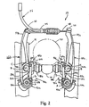
Figure 2 is a front elevational view of the bicycle brake device in accordance with a first embodiment of the present invention with the brake device coupled to the front fork of the bicycle; -
Figure 3 is a right side elevational view of the bicycle brake device illustrated inFigure 2 with the brake device coupled to the front fork of the bicycle; -
Figure 4 is a rear elevational view of the bicycle brake device illustrated inFigures 2 and3 in accordance with the first embodiment of the present invention; -
Figure 5 is a partial, enlarged front elevational view of one of the brake mechanisms of the bicycle brake device illustrated inFigures 1-4 with portions broken away for purposes of illustrating selected parts; -
Figure 6 is a partial, enlarged cross-sectional view of one of the brake mechanisms illustrated inFigures 2-5 as viewed along section line 6-6 ofFig. 5 ; -
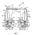
Figure 7 is a front elevational view of the bicycle brake device in accordance with a second embodiment of the present invention with the brake device coupled to the front fork of the bicycle; -
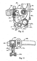
Figure 8 is a right side elevational view of the bicycle brake device illustrated inFigure 7 with the brake device coupled to the front fork of the bicycle; -
Figure 9 is a rear elevational view of the bicycle brake device illustrated inFigures 7 and8 in accordance with the second embodiment of the present invention; -
Figure 10 is a partial, enlarged front elevational view of one of the brake mechanisms of the bicycle brake device illustrated inFigures 7-9 with portions broken away for purposes of illustrating selected parts; -
Figure 11 is a cross-sectional view of one of the brake mechanisms illustrated inFigures 7-10 as viewed along section line 11-11 ofFig. 10 ; -
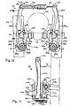
Figure 12 is a front elevational view of the bicycle brake device in accordance with a third embodiment of the present invention with the brake device coupled to the front fork of the bicycle; -
Figure 13 is a right side elevational view of the bicycle brake device illustrated inFigure 12 with the brake device coupled to the front fork of the bicycle; -
Figure 14 is a rear elevational view of the bicycle brake device illustrated inFigures 12 and 13 in accordance with the third embodiment of the present invention; and -
Figure 15 is a partial, enlarged cross-sectional view of one of the brake mechanisms illustrated inFigures 12-14 as viewed along section line 15-15 ofFig. 13 . - Referring initially to
Figure 1 , abicycle brake device 10 is illustrated in accordance with the present invention.Bicycle brake device 10 is illustrated as being fixedly coupled to frame 14 of abicycle 12. Whilebicycle brake device 10 is illustrated as being coupled to front fork 16 ofbicycle frame 14, it will be apparent to those skilled in the art from this disclosure thatbicycle brake device 10 can be coupled to the rear fork (not shown) ofbicycle frame 14 in a conventional manner.Bicycle brake device 10 applies a braking force againstrim 18 ofbicycle wheel 20.Brake device 10 has an increased braking force over prior art brake devices by reducing chatter therein. -
Bicycle brake device 10 is operated in a substantially conventional manner by the rider via a conventional brake operating device orlever 22 which is mounted on thehandle bar 24 ofbicycle 12 in a conventional manner. Bicycles and their various components are well-known in the art, and thus,bicycle 12 and its various components such as abrake operating device 22 will not be discussed or illustrated in detail herein. - As best seen in
Figure 1 , taken in conjunction withFigures 2 and4 ,brake device 10 is operatively coupled to brake operatingdevice 22 via abrake cable 26 having aninner brake wire 28 and anouter casing 30. Basically, the rider will operate thebrake operating device 22 which in turn will cause thebrake device 10 to move inwardly to apply a braking force againstrim 18 of thebicycle wheel 20. Upon releasing thebrake operating device 22, thebicycle brake device 10 will releaserim 18 to allowbicycle wheel 20 to rotate relative to thebicycle frame 14. - As best seen in
Figures 2 and4 ,brake device 10 basically includes a pair ofbrake mechanisms 40a and 40b which are substantially mirror images of each other, except for their connections to brakecable 26.Brake arm 44a is coupled tobrake cable 26 via alock bolt 32 which clampsbrake wire 28 thereto. Theouter casing 30 ofbrake cable 26 is coupled tobrake arm 44b by a connectingarm 34 which is pivotally coupled at one end to brakearm 44b and has theouter casing 30 ofbrake cable 26 coupled to an end thereof. - Basically,
right brake mechanism 40a includes a mountingassembly 42a for attachment to frame 14 ofbicycle 12, abrake arm 44a pivotally coupled to mountingassembly 42a, alinkage assembly 46a coupled to brakearm 44a, abrake shoe assembly 48a movably coupled tobrake arm 44a vialinkage assembly 46a and a return spring 49a (Fig. 4 ) for movingbrake arm 44a,linkage assembly 46a andbrake shoe assembly 48a from a braking position to a release position.Right brake mechanism 40a pivots about pivot axis A. In particular, mountingassembly 42a is supported on pivot pin offrame 14 ofbicycle 12 for pivotingright brake mechanism 40a between a release position and a braking position, and vice versa. During pivotal movement ofright braking mechanism 40a,brake shoe assembly 48a moves its brake pad against therim 18 of thebicycle wheel 20 to restrict rotation ofbicycle wheel 20 relative tobicycle frame 14. Movement ofbicycle shoe assembly 48a is controlled bylinkage assembly 46a to ensure a powerful braking force is obtained. - Likewise, left brake mechanism 40b basically includes a mounting assembly 42b for attachment to frame 14 of
bicycle 12, abrake arm 44b pivotally coupled to mounting assembly 42b, a linkage assembly 46b coupled tobrake arm 44b, a brake shoe assembly 48b movably coupled tobrake arm 44b via linkage assembly 46b and a return spring 49b for movingbrake arm 44b, linkage assembly 46b and brake shoe assembly 48b from a braking position to a release position. In view of the substantial similarities between right and leftbrake mechanisms 40a and 40b, only theright brake mechanism 40a will be described and illustrated in detail herein. Moreover, as used herein, the terms "upper", "lower", "inner", and "outer" are to be interpreted as viewed inFigures 1-4 . - Mounting
assemblies 42a and 42b fixedly couple right and leftbrake mechanisms 40a and 40b to frame 14 via mounting pins orscrews Figure 3 , screws 50a and 50b extend through tubular pivot pins 56a and 56b and are then threaded into mountingposts 51a and 51b offrame 14, respectively. Mountingassemblies 42a and 42b are relatively conventional mounting assemblies. Basically, mountingassemblies 42a and 42b are preferably designed in a manner similar to those disclosed inU.S. Patent No. 5,636,716 to Sugimoto et al. andU.S. Patent No. 5,655,630 to Sugimoto , both of which are assigned to Shimano Inc. The entire disclosures of these two patents are hereby incorporated herein by reference to explain mountingassemblies 42a and 42b, as well as to understand the basic operation of a brake mechanism which utilizes a four-bar linkage assembly. Therefore, mountingassemblies 42a and 42b will not be discussed or illustrated in detail herein. -
Brake arms arms arms brake device 10. As best seen inFigures 2-3 ,brake arm 44a has a first orlower end 52a and an upper or second end 54a.Lower end 52a is pivotally coupled to mountingassembly 42a, while upper end 54a is coupled toinner brake wire 28 ofbrake cable 26. During braking, the upper or second end 54a ofbrake arm 44a is moved against the bias of return spring 49a by movement ofinner brake wire 28 ofbrake cable 26 to apply a braking force againstrim 18 of thebicycle wheel 20.
Accordingly,brake arm 44a rotates about a first pivot axis A which is formed bytubular pivot pin 56a which mountsbrake arm 44a to theframe 14 of thebicycle 12. In addition, a portion oflinkage assembly 46a is coupled totubular pivot pin 56a, as mentioned above. - Left brake arm 40b is similarly constructed, except for its upper end. Accordingly, the parts of
brake arm 44b will be labelled with reference numerals similar to that ofright brake arm 44a, except that the reference numerals will be designated with a letter "b" instead of letter "a". -
Brake arms brake cable 26 in a conventional manner. Specifically, the upper end 54a ofbrake arm 44a is coupled to theinner brake wire 28 ofbrake cable 26 vialock bolt 32 which is received in a threaded hole on the upper end 54a of thebrake arm 44a. Thelock bolt 32 clampsinner brake wire 28 against the upper end 54a ofbrake arm 44a. Theouter casing 30 ofbrake cable 26 is coupled to the upper end 54b ofbrake arm 44b. In particular, as seen inFigures 2 and4 , connectingarm 34 is pivotally coupled to the upper end 54b ofbrake arm 44b at one end and has theouter casing 30 ofbrake cable 26 coupled to its other end. Operation ofbrake operating device 22 causes the upper ends 54a and 54b to move inwardly towards each other so that the brake pads ofbrake shoe assemblies 48a and 48b engages the side surfaces ofrim 18. - Specifically, the upper ends 54a and 54b of
brake arms brake shoe assemblies 48a and 48b coupled thereto vialinkage assemblies 46a and 46b. Therefore, this pivotal movement of thebrake arms brake shoe assemblies 48a and 48b to engage therim 18 of thebicycle wheel 20. Of course, brakearms -
Linkage assemblies 46a and 46b are substantially identical and mirror images of each other and utilize biasingmembers 58a and 58b to provide a stabilizing force thereto for reducing vibrational movement or chatter. In view of the similarities betweenlinkage assemblies 46a and 46b, they will be given identical reference numerals except for the right linkage assembly will be designated with a letter "a" and the left linkage assembly will be designated with a letter "b".Linkage assembly 46a forms a four-bar linkage assembly withbrake arm 44a. In particular,linkage assembly 46a includes an upper or brakeshoe attachment link 60a, aninner link 62a, a lower or fixed link 64a and a portion 66a ofbrake arm 44a forms a four-bar linkage. Portion 66a ofbrake arm 44a is the section ofbrake arm 44a that extends between the attachment points of upper andlower links 60a and 64a to form the fourth link of the four-bar linkage. -
Linkage assembly 46a is designed to movebrake shoe assembly 48a relatively uniformly each time in a generally horizontal direction. More specifically, brakeshoe attachment link 60a has an outer end pivotally coupled to an intermediate portion ofbrake arm 44a and an inner end pivotally coupled to an upper end ofinner link 62a. The lower end ofinner link 62a is in turn pivotally connected to an inner end of the fixed or lower link 64a. The outer end of fixed or lower link 64a is pivotally coupled tobrake arm 44a by thetubular pivot pin 56a for pivoting about the pivot axis A. -
Brake shoe assembly 48a is fixedly coupled to the inner end of brakeshoe attachment link 60a. Asbrake arm 44a moves from a release position to a brake position,linkage assembly 46a controls the movement ofbrake shoe assembly 48a as it moves to engage therim 18 of thebicycle wheel 20. - Brake
shoe attachment link 60a and 60b are substantially identical, except that they are mirror images of each other. Each brakeshoe attachment link 60a or 60b is a substantially U-shaped member which straddles an intermediate portion of thebrake arm shoe attachment link 60a is pivotally coupled tobrake arm 44a via apivot pin 72a for pivotal movement about pivot axis B. The outer end of brakeshoe attachment link 60a has an opening 70a therein for attachingbrake shoe assembly 48a thereto in a conventional manner. -
Inner link 62a is pivotally coupled to brakeshoe attachment link 60a via pivot pin 74a and pivotally coupled to fixed lower link 64a at its lower end via apivot pin 76a. In other words, brakeshoe attachment link 60a andinner link 62a pivot relative to each other about pivot axis C formed by pivot pin 74a, while fixed lower link 64a andinner link 62a rotate relative to each other about pivot axis D formed bypivot pin 76a. - Fixed link 64a is fixedly coupled to mounting
assembly 42a such that during movement ofbrake arm 44a from a release position to a braking position or vice versa, fixed link 64a does not move. Fixed lower link 64a has its inner end coupled to the lower end ofinner link 62a viapivot pin 76a. The outer end of fixed link 64a is coupled totubular pivot pin 56a such thatbrake arm 44a can rotate relative to fixed link 64a about pivot axis A. - In this embodiment, the biasing
members 58a and 58b are positioned between brakeshoe attachment links 60a, 60b andbrake arms linkage assemblies 46a and 46b. In particular, the biasingmembers 58a and 58b apply a force tolinkage assemblies 46a and 46b to take up any play within the pivot points thereof. Accordingly, biasingmembers 58a and 58b reduce vibrational movement and chatter oflinkage assemblies 46a and 46b.Biasing members 58a and 58b also biaslinkage assemblies 46a and 46b from their braking positions to their release positions. In other words, biasingmembers 58a and 58b operate together to normally movebrake shoe assemblies 48a and 48b away fromrim 18 ofbicycle wheel 20. It will be apparent to those skilled in the art that return springs 49a and 49b can be eliminated by installing biasingmembers 58a and 58b which have a sufficient return force to holdbrake arms members 58a and 58b illustrated in the drawings would have to be stronger and thicker than the springs to effectively work as return springs. - As seen in
Figures 5 and 6 , biasingmember 58a is preferably a torsion spring which is constructed of a suitable resilient material such as spring steel.
Biasing member 58a has afirst end 80a for engaging brakeshoe attachment link 60a and asecond end 82a for engagingbrake arm 44a. Torsion spring or biasingmember 58a also has a coiledportion 84a which is positioned about thepivot pin 72a which interconnects brakeshoe attachment link 60a toinner link 62a. Of course, biasing member 58b is similar in construction to biasingmember 58a, and thus, biasing member 58b will not be discussed or illustrated herein. - Preferably, the distance between the axis of
pin 56a and the axis ofpin 72a is equal to the distance between the axis of pivot pin 74a and the axis ofpivot pin 76a. In other words, the distance between axes A and B is substantially equal to the distance between axes C and D. Also, the distance between the axis ofpivot pin 72a and the axis of pivot pin 74a is substantially equal to the distance between the axis ofpivot pin 56a and the axis ofpivot pin 76a. In other words, the distance between axes B and C is substantially equal to the distance between axes A and D. Specifically, the fourpins - In operation, when the rider operates the
brake operating device 22, theinner wire 28 of thebrake cable 26 is pulled within theouter casing 30 of thebrake cable 26 so that the upper ends 54a and 54b of thebrake arms brake arms brake shoe assemblies 48a and 48b being pulled inwardly to press against the side surfaces ofrim 18 of thebicycle wheel 20 to cause a braking action to be performed. In other words,brake arm 44a rotates in a counterclockwise direction aboutpivot pin 56a against the force of return spring 49a, andbrake arm 44b rotates in a clockwise direction about pivot pin 56b against the force of return spring 49b. Once the rider releases thebrake operating device 22, theinner brake wire 28 of thebrake cable 26 is relaxed so that the return spring 49a and 49b causes thebrake arms brake shoe assemblies 48a and 48b are withdrawn from the side surfaces of thebicycle rim 18 so that the brake action is released. - Referring now to
Figures 7-11 , abrake device 110 is illustrated in accordance with a second embodiment of the present invention. This second embodiment differs from the first embodiment in that the biasingmembers shoe attachment link 160a and 160b and theinner link 162a and 162b instead of between the brake arm 144a and 144b and the brakeshoe attachment link 160a and 160b as in the first embodiment. Also, this second embodiment differs from the first embodiment in that the lower or fixedlinks screw U.S. Patent Application Serial No. 08/895,560 , assigned to Shimano Inc. The entire disclosure of Serial No.08/895,560 is hereby incorporated herein by reference. In view of the similarities between the two embodiments, only the main differences between the first and second embodiments will be discussed and illustrated herein. Moreover, since the second embodiment utilizes many of the same parts of the first embodiment, these parts will be given a similar reference numeral. - As best seen in
Figures 7 and9 ,brake device 110 is operatively coupled to a brake operating device via abrake cable 126 having aninner brake wire 128 and anouter casing 130. Basically, the rider will operate the brake operating device which in turn will cause thebrake device 110 to move inwardly to apply a braking force againstrim 118 of thebicycle wheel 120. Upon releasing the brake operating device, thebicycle brake device 110 will releaserim 118 to allowbicycle wheel 120 to rotate relative to the bicycle frame 114. -
Brake device 110 basically includes a pair ofbrake mechanisms 140a and 140b which are substantially mirror images of each other, except for their connections to brakecable 126. Brake arm 144a is coupled tobrake cable 126 via alock bolt 132 which clampsbrake wire 128 thereto. Theouter casing 130 ofbrake cable 126 is coupled to brake arm 144b by a connectingarm 134 which is pivotally coupled at one end to brake arm 144b and has theouter casing 130 ofbrake cable 126 coupled to the other end. - Basically,
right brake mechanism 140a includes a brake arm 144a, a linkage assembly 146a coupled to brake arm 144a for pivotally moving abrake shoe assembly 148a and areturn spring 149a for moving brake arm 144a, linkage assembly 146a andbrake shoe assembly 148a from a braking position to a release position.Right brake mechanism 140a pivots about pivot axis A. During pivotal movement ofright braking mechanism 140a,brake shoe assembly 148a moves its brake pad against therim 118 of thebicycle wheel 120 to restrict rotation ofbicycle wheel 120 relative to bicycle frame 114. Movement ofbicycle shoe assembly 148a is controlled by linkage assembly 146a to ensure a powerful braking force is obtained. - Likewise, left brake mechanism 140b basically includes a brake arm 144b, a linkage assembly 146b coupled to brake arm 144b for pivotally moving a brake shoe assembly 148b and a return spring 149b for moving brake arm 144b, linkage assembly 146b and brake shoe assembly 148b from a braking position to a release position. In view of the substantial similarities between right and left
brake mechanisms 140a and 140b, only theright brake mechanism 140a will be described and illustrated in detail herein. - Linkage assemblies 146a and 146b fixedly couple right and left
brake mechanisms 140a and 140b to frame 114 via mounting pins orscrews openings 153a and 153b (Figure 9 ) in fixedlinks portions 142a and 142b are formed by lower links of linkage assemblies 146a and 146b. Basically, linkage assemblies 146a and 146b are preferably designed in a manner similar to those disclosed in Serial No.08/895,560 . - Brake arms 144a and 144b are preferably constructed of a suitable rigid material. For example, brake arms 144a and 144b can be casted or machined from any suitable material such as aluminum, titanium, dense plastic, ceramic, acrylic, etc. Preferably, brake arms 144a and 144b are constructed of a lightweight material to minimize the weight of
brake device 110. As best seen inFigures 7-9 , brake arm 144a has a first orlower end 152a and an upper orsecond end 154a.Lower end 152a is pivotally coupled to mountingassembly 142a, whileupper end 154a is coupled toinner brake wire 128 ofbrake cable 126. During braking, the upper orsecond end 154a of brake arm 144a is moved against the bias ofreturn spring 149a by movement ofinner brake wire 128 ofbrake cable 126 to apply a braking force againstrim 118 of thebicycle wheel 120. Accordingly, brake arm 144a rotates about a first pivot axis A which is formed by apivot pin 156a. - Left brake arm 144b is similarly constructed, except for its upper end. Accordingly, the parts of brake arm 144b will be labelled with reference numerals similar to that of right brake arm 144a, except that the reference numerals will be designated with a letter "b" instead of letter "a".
- Brake arms 144a and 144b have their
upper ends 154a and 154b coupled tobrake cable 126 in a conventional manner. Specifically, theupper end 154a of brake arm 144a is coupled toinner brake wire 128 ofbrake cable 126 vialock bolt 132 which is received in a threaded hole on theupper end 154a of the brake arm 144a. Thelock bolt 132 clampsinner brake wire 128 against theupper end 154a of brake arm 144a. Theouter casing 130 ofbrake cable 126 is coupled to the upper end 154b of brake arm 144b. In particular, as seen inFigures 7 and9 , connectingarm 134 is pivotally coupled to the upper end 154b of brake arm 144b at one end and has theouter casing 130 ofbrake cable 126 coupled to its other end. Application of the brake operating device causes the upper ends 154a and 154b to move inwardly towards each other so that the brake pads ofbrake shoe assemblies 148a and 148b engages the side surfaces ofrim 118. - Specifically, the upper ends 154a and 154b of brake arms 144a and 144b have
brake shoe assemblies 148a and 148b coupled thereto via linkage assemblies 146a and 146b. Therefore, this pivotal movement of the brake arms 144a and 144b causes the brake pads ofbrake shoe assemblies 148a and 148b to engage therim 118 of thebicycle wheel 120. Of course, brake arms 144a and 144b are normally biased byreturn springs 149a and 149b from their braking positions to their release positions. - Linkage assemblies 146a and 146b are substantially identical and mirror images of each other and utilize biasing
members shoe attachment link 160a, aninner link 162a, a lower or fixedlink 164a and a portion 166a of brake arm 144a forms a four-bar linkage. Portion 166a of brake arm 144a is the section of brake arm 144a that extends between the attachment points of upper andlower links - Linkage assembly 146a is designed to move
brake shoe assembly 148a relatively uniformly each time in a generally horizontal direction. More specifically, brakeshoe attachment link 160a has an outer end pivotally coupled to an intermediate portion of brake arm 144a and an inner end pivotally coupled to an upper end ofinner link 162a. The lower end ofinner link 162a is in turn pivotally connected to an inner end of the fixed orlower link 164a. The outer end of fixed orlower link 164a is pivotally coupled to brake arm 144a by thepivot pin 156a for pivoting about the pivot axis A. -
Brake shoe assembly 148a is fixedly coupled to the inner end of brakeshoe attachment link 160a. As brake arm 144a moves from a release position to a brake position, linkage assembly 146a controls the movement ofbrake shoe assembly 148a as it moves to engage therim 118 of thebicycle wheel 120. - Brake
shoe attachment link 160a and 160b are substantially identical, except that they are mirror images of each other. Each brakeshoe attachment link 160a or 160b is a substantially U-shaped member which straddles an intermediate portion of the brake arm 144a or 144b. The inner end of brakeshoe attachment link 160a is pivotally coupled to brake arm 144a via a pivot pin 172a for pivotal movement about pivot axis B. The outer end of brakeshoe attachment link 160a has anopening 170a therein for attachingbrake shoe assembly 148a thereto in a conventional manner. -
Inner link 162a is pivotally coupled to brakeshoe attachment link 160a via pivot pin 174a and pivotally coupled to fixedlower link 164a at its lower end via apivot pin 176a. In other words, brakeshoe attachment link 160a andinner link 162a pivot relative to each other about pivot axis C formed by pivot pin 174a, while fixedlower link 164a andinner link 162a rotate relative to each other about pivot axis D formed bypivot pin 176a. -
Fixed link 164a has mountingportion 142a located betweentubular pivot pins link 164a does not move.Fixed link 164a has its inner end coupled to the lower end ofinner link 162a viapivot pin 176a. The outer end of fixedlink 164a is coupled totubular pivot pin 156a such that brake arm 144a can rotate relative to fixedlink 164a about pivot axis A. - In this embodiment, the biasing
members shoe attachment links 160a, 160b andinner links 162a, 162b so as to apply a stabilizing force to linkage assemblies 146a and 146b. In particular, the biasingmembers members Biasing members members brake shoe assemblies 148a and 148b away fromrim 118 ofbicycle wheel 120. It will be apparent to those skilled in the art that returnsprings 149a and 149b can be eliminated by installing biasingmembers members - As seen in
Figures 10 and 11 , biasingmember 158a is preferably a torsion spring which is constructed of a suitable resilient material such as spring steel.
Biasing member 158a has a first end 180a for engaging brakeshoe attachment link 160a and asecond end 182a for engaginginner link 162a. Torsion spring or biasingmember 158a also has a coiled portion 184a which is positioned about the pivot pin 174a which interconnects brakeshoe attachment link 160a toinner link 162a. Of course, biasingmember 158b is similar in construction to biasingmember 158a, and thus, biasingmember 158b will not be discussed or illustrated herein. - Preferably, the distance between the axis of
pin 156a and the axis of pin 172a is equal to the distance between the axis of pivot pin 174a and the axis ofpivot pin 176a.
In other words, the distance between axes A and B is substantially equal to the distance between axes C and D. Also, the distance between the axis of pivot pin 172a and the axis of pivot pin 174a is substantially equal to the distance between the axis ofpivot pin 156a and the axis ofpivot pin 176a. In other words, the distance between axes B and C is substantially equal to the distance between axes A and D. Specifically, the fourpins - Referring now to
Figures 12-15 , abrake device 210 is illustrated in accordance with a third embodiment of the present invention. This third embodiment differs from the first and second embodiments in that the return springs 249a and 249b are utilized to perform both the function of normally biasing the brake arms 244a and 244b from braking positions to release positions as well as applying a stabilizing force on each of thelinkage assemblies 246a and 246b to reduce vibrational movement thereof. In view of the similarities between the third embodiment and the two prior embodiments, only the main differences between the third and the prior embodiments will be discussed and illustrated in detail herein. - As best seen in
Figures 12 and14 ,brake device 210 is operatively coupled to the brake operating device via abrake cable 226 having aninner brake wire 228 and anouter casing 230. Basically, the rider will operate the brake operating device which in turn will cause thebrake device 210 to apply a braking force againstrim 218 of thebicycle wheel 220. Upon releasing the brake operating device, thebicycle brake device 210 will releaserim 218 to allowbicycle wheel 220 to rotate relative to thebicycle frame 214. - As best seen in
Figures 12 and14 ,brake device 210 basically includes a pair ofbrake mechanisms 240a and 240b which are substantially mirror images of each other, except for their connections to brakecable 226. Brake arm 244a is coupled toinner brake wire 228 ofbrake cable 226 via alock bolt 232 which clampsinner brake wire 228 thereto. Theouter casing 230 ofbrake cable 226 is coupled to brake arm 244b by a connectingarm 234 which is pivotally coupled at one end to brake arm 244b and has the outer casing ofbrake cable 226 coupled to its other end. - Basically,
right brake mechanism 240a includes a mountingassembly 242a for attachment to frame 214 of the bicycle, a brake arm 244a pivotally coupled to mountingassembly 242a, alinkage assembly 246a coupled to brake arm 244a, a brake shoe assembly 248a movably coupled to brake arm 244a vialinkage assembly 246a and areturn spring 249a for moving brake arm 244a,linkage assembly 246a and brake shoe assembly 248a from a braking position to a release position.Right brake mechanism 240a pivots about pivot axis A. In particular, mountingassembly 242a is supported on pivot pin offrame 214 of the bicycle for supportingright brake mechanism 240a between a release position and a braking position. During pivotal movement ofright braking mechanism 240a, brake shoe assembly 248a moves its brake pad against therim 218 of thebicycle wheel 220 to restrict rotation ofbicycle wheel 220 relative tobicycle frame 214.
Movement of bicycle shoe assembly 248a is controlled bylinkage assembly 246a to ensure a powerful braking force is obtained. - Likewise, left brake mechanism 240b basically includes a mounting
assembly 242b for attachment to frame 214 of the bicycle, a brake arm 244b pivotally coupled to mountingassembly 242b, a linkage assembly 246b coupled to brake arm 244b, a brake shoe assembly 248b movably coupled to brake arm 244b via linkage assembly 246b and a return spring 249b for moving brake arm 244b, linkage assembly 246b and brake shoe assembly 248b from a braking position to a release position. In view of the substantial similarities between right and leftbrake mechanisms 240a and 240b, only theright brake mechanism 240a will be described and illustrated in detail herein. - Mounting
assemblies brake mechanisms 240a and 240b to frame 214 via mountingscrews Figure 12 and 13 , mountingscrews tubular pivot pins 256a and 256b, and are then threaded into mounting posts 251a and 251b, offrame 214, respectively. Mountingassemblies assemblies - Brake arms 244a and 244b are preferably constructed of a suitable rigid material. For example, brake arms 244a and 244b can be cast or machined from any suitable material such as aluminum, titanium, dense plastic, ceramic, acrylic, etc. Preferably, brake arms 244a and 244b are constructed of a lightweight material to minimize the weight of
brake device 210. As best seen inFigures 12-14 , brake arm 244a has a first orlower end 252a and an upper orsecond end 254a.Lower end 252a is pivotally coupled to mountingassembly 242a for movement between a release position and a braking position. In particular, the upper orsecond end 254a of brake arm 244a is moved against the bias ofreturn spring 249a by movement ofinner brake wire 228 ofbrake cable 226 to apply a braking force againstrim 218 of thebicycle wheel 220. Accordingly, brake arm 244a rotates about a first pivot axis A which is formed by atubular pivot pin 256a which mounts brake arm 244a to theframe 214 of the bicycle as well as mounts a portion oflinkage assembly 246a thereto, as discussed below. Left brake arm 240b is similarly constructed, except for its upper end. Accordingly, the parts of brake arm 244b will be labelled with reference numerals similar to that of right brake arm 244a, except that the reference numerals will be designated with a letter "b" instead of letter "a". - Brake arms 244a and 244b have their
upper ends brake cable 226 in a conventional manner. Specifically, theupper end 254a of brake arm 244a is coupled toinner brake wire 228 ofbrake cable 226 vialock bolt 232 which is received in a threaded hole on theupper end 254a of the brake arm 244a. Thelock bolt 232 clampsinner brake wire 228 against theupper end 254a of brake arm 244a. Theouter casing 230 ofbrake cable 226 is coupled to theupper end 254b of brake arm 244b. In particular, as seen inFigure 12 and14 , connectingarm 234 is pivotally coupled to theupper end 254b of brake arm 244b at one end and has theouter casing 230 ofbrake cable 226 coupled to its other end. Application of the brake operating device causes the upper ends 254a and 254b to move inwardly towards each other so that the brake pads of brake shoe assemblies 248a and 248b engages the side surfaces ofrim 218. - Specifically, the upper ends 254a and 254b of brake arms 244a and 244b have brake shoe assemblies 248a and 248b coupled thereto via
linkage assemblies 246a and 246b. Therefore, this pivotal movement of the brake arms 244a and 244b causes the brake pads of brake shoe assemblies 248a and 248b to engage therim 218 of thebicycle wheel 220. -
Linkage assemblies 246a and 246b are substantially identical and mirror images of each other. Therefore,linkage assemblies 246a and 246b will be given identical reference numerals except for the right linkage assembly will be designated with a letter "a" and the left linkage assembly will be designated with a letter "b".Linkage assembly 246a forms a four-bar linkage assembly with brake arm 244a. In particular,linkage assembly 246a includes an upper or brake shoe attachment link 260a, aninner link 262a, a lower or fixed link 264a and aportion 266a of brake arm 244a forms a four-bar linkage.Portion 266a of brake arm 244a is the section of brake arm 244a that extends between the attachment points of upper and lower links 260a and 264a to form the fourth link of the four-bar linkage. -
Linkage assembly 246a is designed to move brake shoe assembly 248a relatively uniformly each time in a generally horizontal direction. More specifically, brake shoe attachment link 260a has an outer end pivotally coupled to an intermediate portion of brake arm 244a and an inner end pivotally coupled to an upper end ofinner link 262a. The lower end ofinner link 262a is in turn pivotally connected to an inner end of the fixed link 264a. The outer end of fixed link 264a is pivotally coupled to brake arm 244a by thepivot pin 256a for pivoting about the pivot axis A. - Brake shoe assembly 248a is fixedly coupled to the inner end of brake shoe attachment link 260a. As brake arm 244a moves from a release position to a brake position,
linkage position 246a controls the movement of brake shoe assembly 248a as it moves to engage therim 218 of thebicycle wheel 220. - Brake shoe attachment link 260a and 260b are substantially identical, except that they are mirror images of each other. Each brake shoe attachment link 260a and 260b is a substantially U-shaped member which straddles an intermediate portion of the brake arm 244a or 244b. The inner end of brake shoe attachment link 260a is pivotally coupled to brake arm 244a via a
pivot pin 272a for pivotal movement about pivot axis B. The outer end of brake shoe attachment link 260a has anopening 270a therein for attaching brake shoe assembly 248a thereto in a conventional manner. -
Inner link 262a is pivotally coupled to brake shoe attachment link 260a via pivot pin 274a and pivotally coupled to fixed lower link 264a at its lower end via apivot pin 276a. In other words, brake shoe attachment link 260a andinner link 262a pivot relative to each other about pivot axis C formed by pivot pin 274a, while fixed lower link 264a andinner link 262a rotate relative to each other about pivot axis D formed bypivot pin 276a. - Fixed link 264a is fixedly coupled to mounting
assembly 242a such that during movement of brake arm 244a from a release position to a braking position or vice versa, fixed link 264a does not move. Fixed link 264a has its inner end coupled to the lower end ofinner link 262a viapivot pin 276a. The outer end of fixed link 264a is coupled topivot pin 256a such that brake arm 244a can rotate relative to fixed link 264a about pivot axis A. - In this embodiment, the
return spring 249a engagespin 261a of brake shoe attachment link 260a to apply a stabilizing force tolinkage assembly 246a. In particular,return spring 249a applies a force tolinkage assembly 246a to take up any play within the pivot points thereof. Accordingly,return spring 249a reduces vibrational movement oflinkage assembly 246a. More specifically, as seen inFigures 13-15 ,return spring 249a is preferably a torsion spring which is constructed of a suitable resilient material such as spring steel. As seen inFigures 14 and 15 return spring 249a has afirst end 280a for engagingpin 261a coupled to brake shoe attachment link 260a and a second end 282a for engaging mountingmember 242a.Return spring 249a also has a coiled portion 284a which is positioned about thepivot pin 256a which pivotally couples brake arm 244a to frame 214. - Preferably, the distance between the axis of
pin 256a and the axis ofpin 272a is equal to the distance between the axis of pivot pin 274a and the axis ofpivot pin 276a. In other words, the distance between axes A and B is substantially equal to the distance between axes C and D. - Also, the distance between the axis of
pivot pin 272a and the axis of pivot pin 274a is substantially equal to the distance between the axis ofpivot pin 256a and the axis ofpivot pin 276a. In other words, the distance between axes B and C is substantially equal to the distance between axes A and D. Specifically, the fourpins
Claims (34)
- A bicycle brake device (10,110,210) comprising first and second brake arms (44,144,244) each having a linkage assembly (46,146,246) connecting a brake shoe (48,148,248) to a respective brake arm (44,144,244) and being movably coupled to said respective brake arm (44,144,244); and a biasing member (58,158,249), characterised in that the biasing member (58,158,249) engages a respective linkage assembly (46,146,246) to apply a stabilizing force to said linkage assembly (46,146,246).
- A bicycle brake device according to claim 1, wherein said biasing member (58,58,249) engages said brake arm (44,144,244) to apply said stabilizing force between said respective linkage assembly (46,146,246) and said respective brake arm (44,144,244).
- A bicycle brake device according to either preceding claim, wherein said biasing member (58,158,249) is a spring with a first end engaging said respective linkage assembly (46,146,246) and a second end engaging said respective brake arm (44,144, 244).
- A bicycle brake device according to any preceding claim, wherein said brake shoe (48,148,248) is coupled to said respective brake arm (44,144,244) via a brake shoe attachment link(60,160,260).
- A bicycle brake device according to claim 4, wherein said biasing member (58,158,249) engages said brake shoe attachment link (60,160,260) of said linkage assembly (46,146, 246).
- A bicycle brake device according to either claim 4 or claim 5, wherein said brake shoe attachment link (60,160,260) of said linkage assembly (46,146,246) is pivotally coupled to a respective brake arm (44,144,244) about a first pivot pin.
- A bicycle brake device according to claim 6, wherein said biasing member (58,158) is a torsion spring with a first end engaging said brake shoe attachment link (60,160) of said respective linkage assembly (46,146) a second end engaging said respective brake arm (44,144) and a coil portion (84,184) positioned about said first pivot pin.
- A bicycle brake device according to any preceding claim, wherein each linkage assembly (46,146,246) has an inner link (62,162,262) with a first end movably coupled to a brake shoe attachment link (60,160,260) and a second end movably coupled to an inner end of a lower link (64,164,264), said brake shoe attachment link (60,160,260) and said lower link (64,164,264) having outer ends movably coupled to said brake arm (44,144,244).
- A bicycle brake device according to claim 8, wherein said biasing member (58,158,249) engages two of said links to apply said stabilizing force therebetween.
- A bicycle brake device according to claim 8 or claim 9, wherein said biasing member (58,158,249) has a first end engaging said brake shoe attachment link (60,160,260) and a second end engaging said inner link (62,162,262).
- A bicycle brake device according to any one of claims 8 to 10, wherein said biasing member is a torsion spring with a first end engaging said brake shoe attachment link (60,160) a second end engaging said inner link (62,162) and a coil portion (84, 184) positioned about a pivot pin C coupling said brake shoe attachment link (60,160) to said inner link (62,162).
- A bicycle brake device according to any preceding claim, wherein said biasing member (249) is a return spring engaging a respective linkage assembly (246) for normally biasing said brake arm (244) from a braking position to a release position, and for applying said stabilizing force on said linkage assembly, (246) to reduce vibrational movement thereof.
- A bicycle brake device according to any one of claims 4 to 12 wherein each linkage assembly (46,146,246) has an inner link (62,162,262) with a first end pivotally coupled to said brake shoe attachment link (60,160,260) of said linkage assembly (46,146,246) about a second pivot pin and a second end pivotally coupled to an inner end of a lower link (64,164,264) about a third pivot pin, said lower link (64,164,264) having an outer end pivotally coupled to said brake (44,144,244) arm about a fourth pivot pin.
- A bicycle brake device according to claim 13, wherein each brake arm (44,144,244) is pivotally mounted about a respective fourth pivot pin.
- A bicycle brake device according to any one of claims 8 to 14, wherein said lower link, (64,164,264) has an attachment portion configured to be fixedly coupled to the bicycle frame.
- A bicycle brake device according to any preceding claim, wherein the device includes a return spring coupled to each brake arm (44,144,244).
- A bicycle brake device according to claim 12, wherein said brake shoe attachment link (60,160,260) of each linkage assembly(46,146,246) is pivotally coupled to a respective brake arm (44,144,244) about a first pivot pin.
- A bicycle brake device according to claim 17, wherein a first end of said biasing member (58,158,249) engages said brake shoe attachment link (60,160,260) of a respective linkage assembly (46,146,246) and a second end engages a respective brake arm (44,144,244).
- A bicycle brake device according to claim 18, wherein each linkage assembly (46,146,246) has an inner link, (62,162,262) with a first end pivotally coupled to said brake shoe attachment link (60,160,260) of said respective linkage assembly (46,146,246) about a second pivot pin and a second end pivotally coupled to an inner end of a lower link (64,164,264) about a third pivot pin, said lower link, (64,164,264) having an outer end pivotally coupled to said respective brake arm (44, 144,244) about a fourth pivot pin.
- A bicycle brake device according to claim 19, wherein said return spring has a coil portion (84,184,284) positioned about said fourth pivot pin.
- A bicycle brake device according to claim 1, wherein each linkage assembly (46,146,246) has an inner link (62,162,262) with a first end pivotally coupled to said brake shoe attachment link (60,160,260) of a respective linkage assembly (46,146,246) about a second pivot pin and a second end pivotally coupled to an inner end of a lower link (64,164,264) about a third pivot pin, said lower link(64,164,264) having an outer end pivotally coupled to said brake arm, (44,144,244) about a fourth pivot pin.
- A bicycle brake device according to claim 21, wherein said lower link (64,164,264) has an attachment portion configured to be fixedly coupled to the bicycle frame.
- A bicycle brake device according to any one of claims 20-22, wherein said fourth pivot pin of each of said brake mechanisms is adapted to be fixedly coupled to the bicycle frame.
- A bicycle brake device as claimed in claim 1 wherein the first and second brake arms (44,144,244) are each pivotable about a first pivot axis, and wherein the linkage assembly (46,146,246) includes:a first link member (60,160,260) having an outer end pivotally coupled to a respective brake arm (44,144,244) about a second pivot axis and an inner end having a brake shoe attachment portion;a second link member (62,162,262) having an upper end pivotally coupled to said inner end of said first link member (60,160,260) about a third pivot axis and a lower end spaced from said upper end;a third link member (64,164,264) having an inner end pivotally coupled to said lower end of said second link member (62,162, 262) about a fourth pivot axis and an outer end pivotally coupled to said first end of said brake arm (44,144,244) about said first pivot axis to form a fourth link member (52,152,252) between said first and second pivot axes; andwherein the biasing member (58,158,249) engages two of said links to apply a stabilizing force therebetween.
- A bicycle brake device according to claim 24, wherein said third link (64,164,264) of each of said brake arms (44,144,244) has an attachment potion adapted to be coupled to the bicycle frame.
- A bicycle brake device according to claim 24, or claim 25, wherein each of said brake arms (44,144,244) has a first pivot pin coupling said outer end of said third link (64,164,264) to said first end of said brake arm (44,144,244) about said first pivot axis with said first pivot pin adapted to be coupled to the bicycle frame.
- A bicycle brake device according to any of claims 24-26, wherein a first end of said biasing member (58,158,249) engages said first link (60,160,260) and a second end engages said fourth link (52,152,252).
- A bicycle brake device according to any one of claims 24-27, wherein said biasing member (58,158,249) of each of said brake mechanisms comprises a return spring which is arranged for both normally biasing said brake arm (44,144,244) between a braking position and a release position and applying said stabilizing force to reduce vibrational movement of said second link (62,162,262).
- A bicycle brake device according to claim 28, wherein said return spring of each of said arms (44,144,244) has a coil portion (84,184,284) positioned about said first pivot axis.
- A bicycle brake device according to any one of claims 24-26, 28 and 29, wherein a first end of said biasing member, (58,158,249) engages said first link (60,160,260) and a second end engages said second link (62,162,262).
- A bicycle brake device according to any one of claims 24-30, wherein each of said brake arms (44,144,244) has a return spring coupled thereto.
- A bicycle brake device according to claim 31, wherein said return spring of each of said brake arms (44,144,244) has a coil portion (84,184,284) positioned about said first pivot axis.
- A bicycle brake device according to any preceding claim, wherein a portion of the linkage assembly (46,146,246) has an attachment portion configured to be fixedly coupled to the bicycle frame.
- A bicycle brake device according to any preceding claim, wherein the biasing member (58,158,249) engages a pair of adjacent links of said linkage assembly (46,146,246).
Applications Claiming Priority (2)
| Application Number | Priority Date | Filing Date | Title |
|---|---|---|---|
| US09/033,300 US6003638A (en) | 1998-03-02 | 1998-03-02 | Bicycle brake device |
| US33300 | 1998-03-02 |
Publications (3)
| Publication Number | Publication Date |
|---|---|
| EP0940333A2 EP0940333A2 (en) | 1999-09-08 |
| EP0940333A3 EP0940333A3 (en) | 2000-06-21 |
| EP0940333B1 true EP0940333B1 (en) | 2008-06-11 |
Family
ID=21869626
Family Applications (1)
| Application Number | Title | Priority Date | Filing Date |
|---|---|---|---|
| EP98308847A Expired - Lifetime EP0940333B1 (en) | 1998-03-02 | 1998-10-30 | Bicycle brake device |
Country Status (5)
| Country | Link |
|---|---|
| US (2) | US6003638A (en) |
| EP (1) | EP0940333B1 (en) |
| CN (1) | CN1093811C (en) |
| DE (1) | DE69839599D1 (en) |
| TW (1) | TW453965B (en) |
Families Citing this family (7)
| Publication number | Priority date | Publication date | Assignee | Title |
|---|---|---|---|---|
| US6264008B1 (en) * | 1999-04-09 | 2001-07-24 | Sram Corporation | Parallel-push brake mechanism for bicycles |
| US7331429B2 (en) * | 2004-11-22 | 2008-02-19 | Gigantex Composite Technologies Co., Ltd. | Brake for composite rim |
| US8066104B2 (en) * | 2009-03-19 | 2011-11-29 | Specialized Bicycle Components, Inc. | Bicycle brake assembly |
| CN102398663A (en) * | 2010-09-16 | 2012-04-04 | 洪铭泽 | Brake structure for controlling front and rear wheel brakes |
| CN102765455A (en) * | 2012-07-25 | 2012-11-07 | 宁波力盟工业有限公司 | Bicycle brake device |
| US9457867B2 (en) | 2013-03-14 | 2016-10-04 | Specialized Bicycle Components, Inc. | Bicycle brake assembly |
| US20170191534A1 (en) * | 2016-01-06 | 2017-07-06 | Shimano Inc. | Bicycle disc brake caliper |
Family Cites Families (15)
| Publication number | Priority date | Publication date | Assignee | Title |
|---|---|---|---|---|
| GB450429A (en) * | 1935-06-12 | 1936-07-17 | Marr Louis Thomas | Improvements in brakes for cycles and the like |
| US3921764A (en) * | 1973-07-25 | 1975-11-25 | William R Mathauser | Self-energizing bicycle brake |
| US4036333A (en) * | 1976-02-13 | 1977-07-19 | Mathauser William R | Bicycle brake shoe with heat dissipating means |
| JPS621873A (en) * | 1985-06-28 | 1987-01-07 | Canon Inc | Washing method for deposit film-forming device |
| JPH02129985A (en) * | 1988-11-09 | 1990-05-18 | Canon Inc | Method of cleaving wafer of semiconductor laser |
| DE4228320A1 (en) * | 1992-08-26 | 1994-03-03 | Weinmann & Co Kg | Bicycle rim brake |
| JP3679822B2 (en) * | 1994-08-24 | 2005-08-03 | 株式会社シマノ | Bicycle brake device |
| US5636716A (en) * | 1995-03-07 | 1997-06-10 | Shimano, Inc. | Bicycle brake device |
| JP3323398B2 (en) * | 1996-06-11 | 2002-09-09 | 株式会社シマノ | Bicycle braking device |
| US5775466A (en) * | 1996-10-04 | 1998-07-07 | Banyas; Michael | Bicycle braking system |
| US5887683A (en) * | 1996-12-23 | 1999-03-30 | Shimano Inc. | Brake adjusting device |
| TW334994U (en) * | 1997-01-24 | 1998-06-21 | Falcon Cycle Parts Co Ltd | Bi-level activating braking system |
| US5913387A (en) | 1997-07-16 | 1999-06-22 | Shimano Inc. | Brake device |
| US5894913A (en) * | 1997-07-17 | 1999-04-20 | Shimano Inc. | Bicycle brake assembly |
| US5960913A (en) * | 1999-02-08 | 1999-10-05 | Kuo; Yung-Pin | Device for adjusting the brake pad relative to the wheel rim of a bicycle |
-
1998
- 1998-03-02 US US09/033,300 patent/US6003638A/en not_active Expired - Lifetime
- 1998-10-27 CN CN98123808A patent/CN1093811C/en not_active Expired - Fee Related
- 1998-10-30 EP EP98308847A patent/EP0940333B1/en not_active Expired - Lifetime
- 1998-10-30 DE DE69839599T patent/DE69839599D1/en not_active Expired - Lifetime
- 1998-11-18 TW TW087119119A patent/TW453965B/en not_active IP Right Cessation
-
1999
- 1999-08-12 US US09/372,899 patent/US6089356A/en not_active Expired - Lifetime
Also Published As
| Publication number | Publication date |
|---|---|
| CN1227815A (en) | 1999-09-08 |
| US6003638A (en) | 1999-12-21 |
| EP0940333A2 (en) | 1999-09-08 |
| CN1093811C (en) | 2002-11-06 |
| DE69839599D1 (en) | 2008-07-24 |
| TW453965B (en) | 2001-09-11 |
| US6089356A (en) | 2000-07-18 |
| EP0940333A3 (en) | 2000-06-21 |
Similar Documents
| Publication | Publication Date | Title |
|---|---|---|
| US8297415B2 (en) | Light weight bicycle brake assembly | |
| EP0731018B1 (en) | Bicycle brake device | |
| EP0999123B1 (en) | Bicycle pedal | |
| EP0940333B1 (en) | Bicycle brake device | |
| US6325401B1 (en) | Bicycle brake mounting structure | |
| EP1167173B1 (en) | Bicycle pedal | |
| EP0891922B1 (en) | Brake device | |
| EP0256473B1 (en) | Auxiliary brake control assembly for bicycle | |
| EP0704371B1 (en) | Bicycle brake device | |
| US5894913A (en) | Bicycle brake assembly | |
| US5924525A (en) | Bicycle brake assembly | |
| AU9120098A (en) | Disk brake mount | |
| JP2001018878A (en) | Bicycle part assembly, cable fixing bolt holding tool, and cable fixing bolt holding method | |
| RU2242395C2 (en) | Bicycle brake | |
| JP3422588B2 (en) | Bicycle braking device | |
| EP1178921B1 (en) | Safety device for racing bicycles provided with braking operating aerodynamic swinging handles | |
| JPH08239076A (en) | Brake device for bicycle | |
| JPS63258284A (en) | Side-pull type caliper brake |
Legal Events
| Date | Code | Title | Description |
|---|---|---|---|
| PUAI | Public reference made under article 153(3) epc to a published international application that has entered the european phase |
Free format text: ORIGINAL CODE: 0009012 |
|
| 17P | Request for examination filed |
Effective date: 19981116 |
|
| AK | Designated contracting states |
Kind code of ref document: A2 Designated state(s): DE FR GB IE IT NL |
|
| AX | Request for extension of the european patent |
Free format text: AL;LT;LV;MK;RO;SI |
|
| RAP1 | Party data changed (applicant data changed or rights of an application transferred) |
Owner name: SHIMANO INC. |
|
| K1C1 | Correction of patent application (title page) published |
Effective date: 19990908 |
|
| PUAL | Search report despatched |
Free format text: ORIGINAL CODE: 0009013 |
|
| AK | Designated contracting states |
Kind code of ref document: A3 Designated state(s): AT BE CH CY DE DK ES FI FR GB GR IE IT LI LU MC NL PT SE |
|
| AX | Request for extension of the european patent |
Free format text: AL;LT;LV;MK;RO;SI |
|
| AKX | Designation fees paid |
Free format text: DE FR GB IT |
|
| RBV | Designated contracting states (corrected) |
Designated state(s): DE FR GB IE IT NL |
|
| 17Q | First examination report despatched |
Effective date: 20060623 |
|
| RAP1 | Party data changed (applicant data changed or rights of an application transferred) |
Owner name: SHIMANO INC. |
|
| GRAP | Despatch of communication of intention to grant a patent |
Free format text: ORIGINAL CODE: EPIDOSNIGR1 |
|
| GRAS | Grant fee paid |
Free format text: ORIGINAL CODE: EPIDOSNIGR3 |
|
| GRAA | (expected) grant |
Free format text: ORIGINAL CODE: 0009210 |
|
| AK | Designated contracting states |
Kind code of ref document: B1 Designated state(s): DE FR GB IE IT NL |
|
| REG | Reference to a national code |
Ref country code: GB Ref legal event code: FG4D |
|
| REF | Corresponds to: |
Ref document number: 69839599 Country of ref document: DE Date of ref document: 20080724 Kind code of ref document: P |
|
| REG | Reference to a national code |
Ref country code: IE Ref legal event code: FG4D |
|
| PG25 | Lapsed in a contracting state [announced via postgrant information from national office to epo] |
Ref country code: NL Free format text: LAPSE BECAUSE OF FAILURE TO SUBMIT A TRANSLATION OF THE DESCRIPTION OR TO PAY THE FEE WITHIN THE PRESCRIBED TIME-LIMIT Effective date: 20080611 |
|
| NLV1 | Nl: lapsed or annulled due to failure to fulfill the requirements of art. 29p and 29m of the patents act | ||
| PLBE | No opposition filed within time limit |
Free format text: ORIGINAL CODE: 0009261 |
|
| STAA | Information on the status of an ep patent application or granted ep patent |
Free format text: STATUS: NO OPPOSITION FILED WITHIN TIME LIMIT |
|
| 26N | No opposition filed |
Effective date: 20090312 |
|
| GBPC | Gb: european patent ceased through non-payment of renewal fee |
Effective date: 20081030 |
|
| REG | Reference to a national code |
Ref country code: IE Ref legal event code: MM4A |
|
| REG | Reference to a national code |
Ref country code: FR Ref legal event code: ST Effective date: 20090630 |
|
| PG25 | Lapsed in a contracting state [announced via postgrant information from national office to epo] |
Ref country code: IT Free format text: LAPSE BECAUSE OF FAILURE TO SUBMIT A TRANSLATION OF THE DESCRIPTION OR TO PAY THE FEE WITHIN THE PRESCRIBED TIME-LIMIT Effective date: 20080611 |
|
| PG25 | Lapsed in a contracting state [announced via postgrant information from national office to epo] |
Ref country code: IE Free format text: LAPSE BECAUSE OF NON-PAYMENT OF DUE FEES Effective date: 20081030 Ref country code: FR Free format text: LAPSE BECAUSE OF NON-PAYMENT OF DUE FEES Effective date: 20081031 |
|
| PG25 | Lapsed in a contracting state [announced via postgrant information from national office to epo] |
Ref country code: GB Free format text: LAPSE BECAUSE OF NON-PAYMENT OF DUE FEES Effective date: 20081030 |
|
| PGFP | Annual fee paid to national office [announced via postgrant information from national office to epo] |
Ref country code: DE Payment date: 20101027 Year of fee payment: 13 |
|
| PG25 | Lapsed in a contracting state [announced via postgrant information from national office to epo] |
Ref country code: DE Free format text: LAPSE BECAUSE OF NON-PAYMENT OF DUE FEES Effective date: 20130501 |
|
| REG | Reference to a national code |
Ref country code: DE Ref legal event code: R119 Ref document number: 69839599 Country of ref document: DE Effective date: 20130501 |