EP0940305A2 - Seat belt assemblies for vehicle - Google Patents
Seat belt assemblies for vehicle Download PDFInfo
- Publication number
- EP0940305A2 EP0940305A2 EP99101771A EP99101771A EP0940305A2 EP 0940305 A2 EP0940305 A2 EP 0940305A2 EP 99101771 A EP99101771 A EP 99101771A EP 99101771 A EP99101771 A EP 99101771A EP 0940305 A2 EP0940305 A2 EP 0940305A2
- Authority
- EP
- European Patent Office
- Prior art keywords
- seat
- row
- seat belt
- webbing
- last
- Prior art date
- Legal status (The legal status is an assumption and is not a legal conclusion. Google has not performed a legal analysis and makes no representation as to the accuracy of the status listed.)
- Granted
Links
Images


Classifications
-
- B—PERFORMING OPERATIONS; TRANSPORTING
- B60—VEHICLES IN GENERAL
- B60R—VEHICLES, VEHICLE FITTINGS, OR VEHICLE PARTS, NOT OTHERWISE PROVIDED FOR
- B60R22/00—Safety belts or body harnesses in vehicles
- B60R22/02—Semi-passive restraint systems, e.g. systems applied or removed automatically but not both ; Manual restraint systems
- B60R22/023—Three-point seat belt systems comprising two side lower and one side upper anchoring devices
Definitions
- the present invention relates to seat belt assemblies for a vehicle and, more particularly to, seat belt assemblies for a vehicle, having plural row of seats, suitable for protecting a passenger sitting on a center seat in an arbitrary row, except the last row.
- a seat belt unit for a rear seat, whose retractor(winder) is arranged within a rear fender is known (refer to Japanese Patent Application Laid-Open No. 6-263005).
- retractors are mounted on the tops of strut type suspension units which are located at the sides of the back of the rear seats (in a case where there are a plurality of separate backs of the respective seats, then at the right and the left sides of the rightmost and the leftmost backs, respectively), and anchors(slip guides) are mounted on the rear pillars which are located above the retractors.
- the direction of each webbing, pulled out from the retractor is changed to the front lower oblique direction by the anchor. In this manner, the seat belt unit is installed for a rear seat.
- a vehicle in which seats are arranged in three rows, in the length direction of a vehicle, where the second row is designed for providing seats for three passengers, and seat or seats in third row are detachable or foldable, so as to provide room for freight, by detaching or folding the seat or seats in the third row, is known.
- three-point support type seat belt units are provided for a right seat 21 and a left seat 22 in the third row.
- the seat belt unit or units for the third row become useless.
- three-point support type seat belt units are also provided for a right seat 11 and a left seat 13 in the second row, however, no seat belt unit or a two-point support type seat belt unit is generally provided for a center seat 12.
- a three-point support type seat belt unit for the center seat 12 for a security purpose to protect a passenger seating there.
- the present invention has been made in consideration of the above situation, and has as its object to design a seat belt unit for the last row, in a vehicle having plural rows of seats where the second to the last seat row is for providing seats for three passengers, so as to be usable in the second to the last seat row.
- a seat belt unit for protecting a passenger on a seat in a last row is configured so that a webbing is pulled out via an anchor, as a fulcrum, provided on a rear pillar of the vehicle, and has enough length to be used as a webbing for protecting a passenger on a center seat, in the width direction, of the second to the last seat row.
- the seat belt unit for the last row is also used for the center seat of the second to the last seat row. Accordingly, the seat belt unit can be shared by the last row and the center seat of the second to the last seat row, thereby it becomes unnecessary to provide a seat belt unit exclusively for the center seat of the second to the last seat row.
- the seat belt unit for the last row is also used for the center seat of the second to the last seat row, thereby, it is unnecessary to design an arrangement of seat belt units by taking the possible seat arrangements into consideration, which reduces cost for designing the vehicle.
- the webbing has a fixed tang which is provided at an end of the webbing and a slide tang designed to be slide along the webbing.
- the seat belt unit of the present invention an optimized configuration of the seat belt unit of the present invention is specified. More specifically, according to the seat belt unit, the fixed tang is engaged with a buckle provided on one side of a seated passenger, then a slide tang is engaged with a buckle provided on the other side of the passenger, thereby the seat belt unit functions as a three-point support type seat belt unit for the passenger.
- the seat belt unit functions as a three-point support type seat belt unit for the passenger.
- the webbing of the seat belt unit provided for the last row can be easily pulled out to the position of the center seat of the second to the last seat row, thereby it is possible to use the seat belt unit provided for the last row for the center seat of the second to the last seat row under proper state of the webbing.
- a seat belt unit for protecting a passenger in a rightmost or leftmost seat, in the width direction, of the second to the last seat row is provided, and a mounting position of an anchor for the webbing of the seat belt unit for the last row is higher than a mounting position of an anchor, as a fulcrum, used when pulling out a webbing of the seat belt unit for the second to the last seat row.
- the anchor of the seat belt unit for the last row in the elevated position when using the seat belt unit, provided for the last row, for the center seat of the second to the last seat row, it is possible to pull the webbing from the rear upper position to the front with respect to a passenger seated in the center seat. Accordingly, the webbing is provided at an optimum angle for the passenger seated in the center seat, thus, it is possible to protect the passenger.
- the anchor for the webbing of the seat belt unit for the last row is preferably provided on the rear pillar of the vehicle, and a rotatable range of the anchor about a rotation axis is between a direction for pulling out the webbing toward the last row of seats and a direction for pulling out the webbing toward a seat in the second to the last seat row.
- an elevation of a seat of the last row is preferably higher than an elevation of a seat of the second to the last seat row.
- the webbing is provided at an optimum angle for the passenger seated in the last row. Accordingly, the webbing is arranged at the best angle for both a passenger seated in the last row and a passenger seated in the center seat of the second to the last seat row, thereby it is possible to protect both passengers.
- the foregoing object is also attained by providing seat belt assemblies for a vehicle in which three rows of seats are arranged in a length direction of the vehicle, the second row is designed for providing seats for three passengers, and a seat or seats in the third row is/are detachable or foldable.
- a seat belt unit for protecting a passenger on a seat of the third row is configured so that a webbing is pulled out via an anchor, as a fulcrum, provided on a rear pillar of the vehicle, has enough length to be used as a webbing for protecting a passenger on a center seat, in the width direction, of the second row, has a fixed tang which is provided at an end of said webbing and a slide tang designed to be slide along said webbing, and is designed to be stored behind a trim panel when wound by a retractor when it is not used.
- the seat belt unit for the third row can be used as a seat belt unit for the center seat of the second row when the third row is not used, thereby realizing an effective use of the seat belt unit provided for the third row.
- the webbing is wound up by the retractor. Since a top (clamping) end of the webbing is not fixed to the vehicle body, the webbing is wound up until the fixed tang provided at the end reaches the anchor, and the webbing is stored behind a trim panel.
- the webbing is not visible when it is not used, thus, the interior of the vehicle looks attractive.
- Fig. 1 shows an arrangement of seats in a vehicle to which seat belt assemblies for the vehicle according to the embodiment of the present invention are applied.
- the vehicle has a form of, so called, a station wagon in which three rows of seats are arranged in the length direction of the vehicle.
- the second row is designed for providing seats for three passengers.
- the third row i.e., the last row, is designed for providing seats for two passengers.
- a seat or seats in the third row are designed to be detachable or foldable, and when the seat or seats in the third row are detached or folded, room for freight is provided behind the second row.
- Figs. 2 and 3 show a rear part of the inside of the vehicle where the second and third rows of seats are arranged.
- reference numeral 31 denotes a seat belt unit for the right seat 11 in the second row; and 41, a seat belt unit for the right seat 21 of the third row.
- seat belt units for the left seat 13 in the second row and the left seat 22 in the third row are not shown.
- the third row is arranged in an elevated position from the position of the second row, as shown in Fig. 2, so that seating position of the third row is higher by H1 than seating position of the second row.
- the seat belt unit 31 for the right seat 11 in the second row comprises a retractor 31a mounted on a C pillar 52 which is behind a right-side trim panel 6 and located in front of a rear side window 51, an anchor 31b mounted inside of the vehicle in the trim panel 6 above the C pillar 52, and a webbing 31c which is wound up by the retractor 31a.
- the webbing 31c is pulled out into the inside of the vehicle through a slit 61 provided on the trim panel 6, and the revealing end of the webbing is fixed on a floor 53. Between the revealing end of the webbing 31c and the anchor 31b, a tang 31d which slides along the webbing 31c is provided.
- the seat belt unit 41 for the right seat 21 of the third row comprises a retractor 41a mounted on a D pillar 54 which is behind the trim panel 6 and located behind the rear side window 51, an anchor 41b mounted inside of the vehicle on the trim panel 6 above the D pillar 54, and a webbing 41c which is wound up by the retractor 41a.
- the webbing 41c is pulled out into the inside of the vehicle through a slit 62 provided on the trim panel 6. Further, as shown in Fig.
- the webbing 41c has two tangs; one is a fixed tang 41d which is fixed at a revealing end of the webbing 41c and the other is a slide tang 41e, provided between the fixed tang 41d and the anchor 41b, which slides along the webbing 41c, differing from the webbing 31c of the seat belt unit 31 of the second row.
- the webbing 41c has enough length to reach the second row.
- the anchor 41b is provided at a higher position by H2 (Fig. 2) than the position of the anchor 31b. Further, the anchors 31b and 41b are respectively configured rotatable about an axis which extends in the width direction of the vehicle. A rotatable angle of the anchor 41b is set greater than a rotatable angle of the anchor 31b. More specifically, the anchor 41b is designed rotatable until it faces toward the second row (refer to a two-dot-dash line showing outline of 41b in Fig. 2).
- the seat belt unit 31 is for protecting a passenger seated in the right seat 11 in the second row by fastening the tang 31d to a buckle 11a, provided on the left of the seat 11, as shown in Figs. 2 and 3.
- the seat belt unit 41 is for protecting a passenger seated in the right seat 21 of the third row by fastening the fixed tang 41d to a first buckle 21a fixed on the floor 53, then fastening the slide tang 41e to a second buckle 21b provided on the left side of the seat 21.
- the fixed tang 41d of the seat belt unit 41 is fastened to a first buckle 12a provided on the right of the center seat 12 of the second row, then the slide tang 41e is fastened to a second buckle 12b provided on the left side of the center seat 12.
- the seat belt unit 41, provided for the third row can be used as a seat belt unit for the center seat 12 of the second row.
- the anchor 41b of the seat belt unit 41 is arranged at a higher position than the position of the anchor 31b of the seat belt unit 31, and the anchor 41b is designed rotatable to completely face to the second row, it is possible to pull out the webbing 41c toward the front, i.e., toward the passenger in the center seat 12 of the second row, at a proper angle from his/her shoulder. Further, since the third row is set at an elevated position from the second row, the webbing 41c is pulled out toward a passenger seated in the right seat 21 of the third row at a proper angle from his/her shoulder. Thus, the seat belt unit 41 can protect both the passenger in the seat 21 of the third row and the passenger in the seat 12 of the second row.
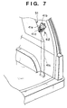
- the webbing 41b is wound up by the retractor 41a until the fixed tang 41d and the slide tang 41e reach the anchor 41b when it is not needed. Accordingly, in a case where a seat or seats in the third row are detached to use the room behind the second row for carrying freight, for instance, with one end of the webbing 41b being fixed on the floor (shown by dot-dash lines in Fig. 7), the webbing 41c does not tangle with the freight while loading and unloading on/from the vehicle. As a result, it increases convenience of the vehicle as well as the inside of the vehicle looks attractive since the webbing 41c is stored behind the trim panel.
- the seat belt unit 41 for the third row can be also used as a seat belt unit for the center seat 12 of the second row, it is possible to realize an effective use of the seat belt unit 41 when it is not used in the third row.
- the seat belt unit 41 for the third row can be used as a seat belt unit for the center seat 12 of the second row, it is not necessary to design an arrangement of seat belt units in consideration of possible seat arrangements, which reduces cost of vehicle design.
- the seat belt unit 41 for the right seat 21 of the third row is used as a seat belt unit for the center seat 12 of the second row in the above embodiment, however, a seat belt unit for the left seat 22 in the third row may be used for the same purpose, for instance.
- three rows of seats are arranged in the length direction in the vehicle, however, the number of rows of seats is not limited to this.
- a vehicle e.g., sedan type
- a seat belt unit for the rear seat may be used for the middle seat of the front row.
- the present invention is also applicable to, e.g., a van having a body of the same shape, but with only two rows of seats, and room behind the second row for freight.
- a passenger in the center seat of the second row can use the seat belt unit, anytime.
- the same arrangement of seat belt units may be used for a station wagon and a van, which makes possible to reduce manufacturing cost.
- the seat belt unit 41 for the third row is used as a seat belt unit for the center seat 12 of the second row when the third row is detached in the above embodiment; however, the present invention is not limited to this, and when at least either one of the right and left seats 21 and 22 in the third row is not occupied, the seat belt unit for the vacant seat can be used for the center seat 12.
- the seat belt units for a vehicle as described in the above embodiment, it is possible to pull out the webbing of the seat belt unit for the last row until it reaches the center seat of the second to the last seat row, thus, the seat belt unit for the last row is also used for the center seat of the second to the last seat row. Accordingly, the seat belt unit can be shared by the last row and the center seat of the second to the last seat row, thereby it becomes unnecessary to provide a seat belt unit exclusively for the center seat of the second to the last seat row.
- seat belt assemblies of the same type can be used in different types of vehicles; thus, a manufacturing cost is reduced. Further, it is unnecessary to design an arrangement of seat belt units by taking the possible seat arrangements into consideration, which reduces cost for designing a vehicle.
- the seat belt assemblies for a vehicle as described in the above embodiment only a base end of the webbing has to be fixed on the vehicle body, and it is not necessary to fix the both ends, i.e., the base end and the top end, of the webbing on the vehicle body for configuring a three-point support seat belt unit. Accordingly, the webbing of the seat belt unit provided for the last row can be easily pulled out to the position of the center seat of the second to the last seat row, thereby it is possible to use the seat belt unit provided for the last row for the center seat of the second to the last seat row under proper state of the webbing.
- the anchor of the seat belt unit for the last row in an elevated position from the position of the anchor of the second to the last seat row, when using the seat belt unit, provided for the last row, for the center seat of the second to the last seat row, it is possible to pull the webbing from the rear upper position to the front with respect to a passenger seated in the center seat. Accordingly, the webbing is provided at the optimum angle for the passenger seated in the center seat.
- the webbing is provided at an optimum angle for the passenger seated in the last row. Accordingly, the webbing is arranged at the best angle for both a passenger seated in the last row and a passenger seated in the center seat of the second to the last seat row, thereby it is possible to protect either of the passengers.
- the seat belt unit for the third row can be used as a seat belt unit for the center seat of the second row when the third row is not used, thereby realizing an effective use of the seat belt unit provided for the third row.
- the webbing is stored behind the trim panel.
- the webbing is not visible when it is not used, thus, the interior of the vehicle looks attractive.
Abstract
Description
- The present invention relates to seat belt assemblies for a vehicle and, more particularly to, seat belt assemblies for a vehicle, having plural row of seats, suitable for protecting a passenger sitting on a center seat in an arbitrary row, except the last row.
- Conventionally, a seat belt unit, for a rear seat, whose retractor(winder) is arranged within a rear fender is known (refer to Japanese Patent Application Laid-Open No. 6-263005). In this type of seat belt units, retractors are mounted on the tops of strut type suspension units which are located at the sides of the back of the rear seats (in a case where there are a plurality of separate backs of the respective seats, then at the right and the left sides of the rightmost and the leftmost backs, respectively), and anchors(slip guides) are mounted on the rear pillars which are located above the retractors. The direction of each webbing, pulled out from the retractor, is changed to the front lower oblique direction by the anchor. In this manner, the seat belt unit is installed for a rear seat.
- As shown in Fig. 1, a vehicle in which seats are arranged in three rows, in the length direction of a vehicle, where the second row is designed for providing seats for three passengers, and seat or seats in third row are detachable or foldable, so as to provide room for freight, by detaching or folding the seat or seats in the third row, is known.
- In a vehicle of this type, three-point support type seat belt units are provided for a
right seat 21 and aleft seat 22 in the third row. When a seat or seats in the third row are detached or folded, for instance, the seat belt unit or units for the third row become useless. - Further, three-point support type seat belt units are also provided for a
right seat 11 and aleft seat 13 in the second row, however, no seat belt unit or a two-point support type seat belt unit is generally provided for acenter seat 12. - However, it is preferable to provide a three-point support type seat belt unit for the
center seat 12 for a security purpose to protect a passenger seating there. - Accordingly, it is considered to provide a three-point support type seat belt unit for the
center seat 12 within either right or left fender. In such a case, however, since the retractors of the seat belt units for theright seat 11 and theleft seat 13 are already mounted in both of the right and left fenders, it is difficult to realize the above arrangement due to problems of space and strength for mounting an extra retractor in the fender. - Further, different types of vehicles, using vehicle bodies of the same type, are manufactured, such as a van having two rows of seats, and a station wagon having three rows of seats. When three rows of seats are arranged, it is tended to provide no seat belt unit for the center seat of the second row, whereas, when two rows of seats are installed, it is tended to provide a three-point support type seat belt unit for the center seat of the rear row. However, in such cases, it is necessary to change the mounting positions of seat belt units for the different types of vehicles, which increases manufacturing cost.
- Furthermore, there is a station wagon which allows a user to change the number of rows of seats, between two and three, depending upon user utilization. Accordingly, it is necessary to design an arrangement of seat belt units by taking all the possible seat arrangements into consideration, which increases the cost of a vehicle.
- The present invention has been made in consideration of the above situation, and has as its object to design a seat belt unit for the last row, in a vehicle having plural rows of seats where the second to the last seat row is for providing seats for three passengers, so as to be usable in the second to the last seat row.
- According to the present invention, the foregoing object is attained by providing seat belt assemblies for a vehicle in which plural rows of seats are arranged in a length direction of the vehicle and a second to the last seat row is designed for providing seats for three passengers. In the seat belt assemblies, a seat belt unit for protecting a passenger on a seat in a last row is configured so that a webbing is pulled out via an anchor, as a fulcrum, provided on a rear pillar of the vehicle, and has enough length to be used as a webbing for protecting a passenger on a center seat, in the width direction, of the second to the last seat row.
- With the aforesaid configuration, it is possible to pull out the webbing of the seat belt unit for the last row until it reaches the center seat of the second to the last seat row, thus, the seat belt unit for the last row is also used for the center seat of the second to the last seat row. Accordingly, the seat belt unit can be shared by the last row and the center seat of the second to the last seat row, thereby it becomes unnecessary to provide a seat belt unit exclusively for the center seat of the second to the last seat row.
- Further, when designing a van and a station wagon using the same type of vehicle bodies, it is unnecessary to change arrangements of seat belt units for each respective vehicle, since seat belt assemblies of the same type can be used in both types of vehicles. As a result, manufacturing cost is reduced.
- Furthermore, in a station wagon, the seat belt unit for the last row is also used for the center seat of the second to the last seat row, thereby, it is unnecessary to design an arrangement of seat belt units by taking the possible seat arrangements into consideration, which reduces cost for designing the vehicle.
- Preferably, the webbing has a fixed tang which is provided at an end of the webbing and a slide tang designed to be slide along the webbing.
- By the above configuration, an optimized configuration of the seat belt unit of the present invention is specified. More specifically, according to the seat belt unit, the fixed tang is engaged with a buckle provided on one side of a seated passenger, then a slide tang is engaged with a buckle provided on the other side of the passenger, thereby the seat belt unit functions as a three-point support type seat belt unit for the passenger. With the foregoing configuration, only a base end of the webbing has to be fixed on the vehicle body, and it is not necessary to fix the both ends, i.e., the base end and a top end, of the webbing to the vehicle body for configuring a three-point support seat belt unit. Accordingly, the webbing of the seat belt unit provided for the last row can be easily pulled out to the position of the center seat of the second to the last seat row, thereby it is possible to use the seat belt unit provided for the last row for the center seat of the second to the last seat row under proper state of the webbing.
- Preferably, a seat belt unit for protecting a passenger in a rightmost or leftmost seat, in the width direction, of the second to the last seat row is provided, and a mounting position of an anchor for the webbing of the seat belt unit for the last row is higher than a mounting position of an anchor, as a fulcrum, used when pulling out a webbing of the seat belt unit for the second to the last seat row.
- With the above configuration, by arranging the anchor of the seat belt unit for the last row in the elevated position, when using the seat belt unit, provided for the last row, for the center seat of the second to the last seat row, it is possible to pull the webbing from the rear upper position to the front with respect to a passenger seated in the center seat. Accordingly, the webbing is provided at an optimum angle for the passenger seated in the center seat, thus, it is possible to protect the passenger.
- Further, the anchor for the webbing of the seat belt unit for the last row is preferably provided on the rear pillar of the vehicle, and a rotatable range of the anchor about a rotation axis is between a direction for pulling out the webbing toward the last row of seats and a direction for pulling out the webbing toward a seat in the second to the last seat row.
- With this configuration, when using the seat belt unit, provided for the last row, for the center seat of the second to the last seat row, the angle of the webbing is changed to a proper angle.
- Further, an elevation of a seat of the last row is preferably higher than an elevation of a seat of the second to the last seat row.
- With this configuration, since the position of seats in the last row is arranged in an elevated position from the position in the second to the last seat row, in a case where the anchor of the seat belt unit for the last row is arranged in the upper position, the webbing is provided at an optimum angle for the passenger seated in the last row. Accordingly, the webbing is arranged at the best angle for both a passenger seated in the last row and a passenger seated in the center seat of the second to the last seat row, thereby it is possible to protect both passengers.
- Further, the foregoing object is also attained by providing seat belt assemblies for a vehicle in which three rows of seats are arranged in a length direction of the vehicle, the second row is designed for providing seats for three passengers, and a seat or seats in the third row is/are detachable or foldable. In the seat belt assemblies, a seat belt unit for protecting a passenger on a seat of the third row is configured so that a webbing is pulled out via an anchor, as a fulcrum, provided on a rear pillar of the vehicle, has enough length to be used as a webbing for protecting a passenger on a center seat, in the width direction, of the second row, has a fixed tang which is provided at an end of said webbing and a slide tang designed to be slide along said webbing, and is designed to be stored behind a trim panel when wound by a retractor when it is not used.
- With the above configuration, the seat belt unit for the third row can be used as a seat belt unit for the center seat of the second row when the third row is not used, thereby realizing an effective use of the seat belt unit provided for the third row.
- Further, when the seat belt unit for the third row is not used, the webbing is wound up by the retractor. Since a top (clamping) end of the webbing is not fixed to the vehicle body, the webbing is wound up until the fixed tang provided at the end reaches the anchor, and the webbing is stored behind a trim panel. As a result, when the third row is detached to make room for freight behind the second row, for instance, it is possible to prevent the webbing tangling with the freight while loading and unloading the freight. In addition, the webbing is not visible when it is not used, thus, the interior of the vehicle looks attractive.
- Other features and advantages of the present invention will be apparent from the following description taken in conjunction with the accompanying drawings, in which like reference characters designate the same or similar parts throughout the figures thereof.
- The accompanying drawings, which are incorporated in and constitute a part of the specification, illustrate an embodiment of the invention and, together with the description, serve to explain the principles of the invention.
- Fig. 1 is a perspective view showing an arrangement of seats in a vehicle to which seat belt assemblies for the vehicle according to the embodiment of the present invention is provided;
- Fig. 2 is a side view showing a rear part of the inside of the vehicle;
- Fig. 3 is a perspective view of the rear part of the inside of the vehicle;
- Fig. 4 shows a configuration of a seat belt unit for a third row;
- Fig. 5 is a side view showing a case where the seat belt unit for the third row is used for a center seat of the second row;
- Fig. 6 is a perspective view showing the case where the seat belt unit for the third row is used for the center seat of the second row; and
- Fig. 7 is a perspective view of a part of the vehicle seen from the back when the seat belt unit for the third row is not used.
-
- A preferred embodiment of the present invention will be described in detail below in accordance with the accompanying drawings.
- Fig. 1 shows an arrangement of seats in a vehicle to which seat belt assemblies for the vehicle according to the embodiment of the present invention are applied. The vehicle has a form of, so called, a station wagon in which three rows of seats are arranged in the length direction of the vehicle. Among the three rows of seats, the second row is designed for providing seats for three passengers. Further, the third row, i.e., the last row, is designed for providing seats for two passengers. A seat or seats in the third row are designed to be detachable or foldable, and when the seat or seats in the third row are detached or folded, room for freight is provided behind the second row.
- Figs. 2 and 3 show a rear part of the inside of the vehicle where the second and third rows of seats are arranged. In Figs. 2 and 3,
reference numeral 31 denotes a seat belt unit for theright seat 11 in the second row; and 41, a seat belt unit for theright seat 21 of the third row. Note, in Figs. 2 and 3, seat belt units for theleft seat 13 in the second row and theleft seat 22 in the third row are not shown. - The third row is arranged in an elevated position from the position of the second row, as shown in Fig. 2, so that seating position of the third row is higher by H1 than seating position of the second row.
- The
seat belt unit 31 for theright seat 11 in the second row comprises aretractor 31a mounted on aC pillar 52 which is behind a right-sidetrim panel 6 and located in front of arear side window 51, ananchor 31b mounted inside of the vehicle in thetrim panel 6 above theC pillar 52, and awebbing 31c which is wound up by theretractor 31a. Thewebbing 31c is pulled out into the inside of the vehicle through aslit 61 provided on thetrim panel 6, and the revealing end of the webbing is fixed on afloor 53. Between the revealing end of thewebbing 31c and theanchor 31b, atang 31d which slides along thewebbing 31c is provided. - The
seat belt unit 41 for theright seat 21 of the third row comprises aretractor 41a mounted on aD pillar 54 which is behind thetrim panel 6 and located behind therear side window 51, ananchor 41b mounted inside of the vehicle on thetrim panel 6 above theD pillar 54, and awebbing 41c which is wound up by theretractor 41a. Thewebbing 41c is pulled out into the inside of the vehicle through aslit 62 provided on thetrim panel 6. Further, as shown in Fig. 4, thewebbing 41c has two tangs; one is a fixedtang 41d which is fixed at a revealing end of thewebbing 41c and the other is aslide tang 41e, provided between the fixedtang 41d and theanchor 41b, which slides along thewebbing 41c, differing from thewebbing 31c of theseat belt unit 31 of the second row. Thewebbing 41c has enough length to reach the second row. - The
anchor 41b is provided at a higher position by H2 (Fig. 2) than the position of theanchor 31b. Further, theanchors anchor 41b is set greater than a rotatable angle of theanchor 31b. More specifically, theanchor 41b is designed rotatable until it faces toward the second row (refer to a two-dot-dash line showing outline of 41b in Fig. 2). - Next, functions of the
seat belt units - The
seat belt unit 31 is for protecting a passenger seated in theright seat 11 in the second row by fastening thetang 31d to abuckle 11a, provided on the left of theseat 11, as shown in Figs. 2 and 3. Theseat belt unit 41 is for protecting a passenger seated in theright seat 21 of the third row by fastening the fixedtang 41d to afirst buckle 21a fixed on thefloor 53, then fastening theslide tang 41e to asecond buckle 21b provided on the left side of theseat 21. - Next, a case where a seat or seats in the third row are detached is explained. As shown in Figs. 5 and 6, the fixed
tang 41d of theseat belt unit 41 is fastened to afirst buckle 12a provided on the right of thecenter seat 12 of the second row, then theslide tang 41e is fastened to asecond buckle 12b provided on the left side of thecenter seat 12. In this manner, theseat belt unit 41, provided for the third row, can be used as a seat belt unit for thecenter seat 12 of the second row. - Since the
anchor 41b of theseat belt unit 41 is arranged at a higher position than the position of theanchor 31b of theseat belt unit 31, and theanchor 41b is designed rotatable to completely face to the second row, it is possible to pull out thewebbing 41c toward the front, i.e., toward the passenger in thecenter seat 12 of the second row, at a proper angle from his/her shoulder. Further, since the third row is set at an elevated position from the second row, thewebbing 41c is pulled out toward a passenger seated in theright seat 21 of the third row at a proper angle from his/her shoulder. Thus, theseat belt unit 41 can protect both the passenger in theseat 21 of the third row and the passenger in theseat 12 of the second row. - Further, as shown in Fig. 7, the
webbing 41b is wound up by theretractor 41a until the fixedtang 41d and theslide tang 41e reach theanchor 41b when it is not needed. Accordingly, in a case where a seat or seats in the third row are detached to use the room behind the second row for carrying freight, for instance, with one end of thewebbing 41b being fixed on the floor (shown by dot-dash lines in Fig. 7), thewebbing 41c does not tangle with the freight while loading and unloading on/from the vehicle. As a result, it increases convenience of the vehicle as well as the inside of the vehicle looks attractive since thewebbing 41c is stored behind the trim panel. - According to the embodiment as described above, the
seat belt unit 41 for the third row can be also used as a seat belt unit for thecenter seat 12 of the second row, it is possible to realize an effective use of theseat belt unit 41 when it is not used in the third row. - Further, since the
seat belt unit 41 for the third row can be used as a seat belt unit for thecenter seat 12 of the second row, it is not necessary to design an arrangement of seat belt units in consideration of possible seat arrangements, which reduces cost of vehicle design. - The present invention is not limited to the above embodiment and various changes and modifications can be made within the spirit and scope of the present invention. More specifically, the
seat belt unit 41 for theright seat 21 of the third row is used as a seat belt unit for thecenter seat 12 of the second row in the above embodiment, however, a seat belt unit for theleft seat 22 in the third row may be used for the same purpose, for instance. - Further, in the above embodiment, three rows of seats are arranged in the length direction in the vehicle, however, the number of rows of seats is not limited to this. For instance, when a vehicle (e.g., sedan type) has two rows of seats where the front row has a driver's seat, a front passenger seat, and another seat between the two seats, a seat belt unit for the rear seat may be used for the middle seat of the front row.
- Furthermore, a case where the present invention is applied to a station wagon is explained in the above embodiment, however, the present invention is also applicable to, e.g., a van having a body of the same shape, but with only two rows of seats, and room behind the second row for freight. By providing the same type of seat belt unit as that of the station wagon to the van, a passenger in the center seat of the second row can use the seat belt unit, anytime. Thus, the same arrangement of seat belt units may be used for a station wagon and a van, which makes possible to reduce manufacturing cost.
- Further, the
seat belt unit 41 for the third row is used as a seat belt unit for thecenter seat 12 of the second row when the third row is detached in the above embodiment; however, the present invention is not limited to this, and when at least either one of the right and leftseats center seat 12. - According to the seat belt assemblies for a vehicle as described in the above embodiment, it is possible to pull out the webbing of the seat belt unit for the last row until it reaches the center seat of the second to the last seat row, thus, the seat belt unit for the last row is also used for the center seat of the second to the last seat row. Accordingly, the seat belt unit can be shared by the last row and the center seat of the second to the last seat row, thereby it becomes unnecessary to provide a seat belt unit exclusively for the center seat of the second to the last seat row.
- Further, seat belt assemblies of the same type can be used in different types of vehicles; thus, a manufacturing cost is reduced. Further, it is unnecessary to design an arrangement of seat belt units by taking the possible seat arrangements into consideration, which reduces cost for designing a vehicle.
- Further, according to the seat belt assemblies for a vehicle as described in the above embodiment, only a base end of the webbing has to be fixed on the vehicle body, and it is not necessary to fix the both ends, i.e., the base end and the top end, of the webbing on the vehicle body for configuring a three-point support seat belt unit. Accordingly, the webbing of the seat belt unit provided for the last row can be easily pulled out to the position of the center seat of the second to the last seat row, thereby it is possible to use the seat belt unit provided for the last row for the center seat of the second to the last seat row under proper state of the webbing.
- Further, according to the seat belt assemblies for a vehicle as described in the above embodiment, by arranging the anchor of the seat belt unit for the last row in an elevated position from the position of the anchor of the second to the last seat row, when using the seat belt unit, provided for the last row, for the center seat of the second to the last seat row, it is possible to pull the webbing from the rear upper position to the front with respect to a passenger seated in the center seat. Accordingly, the webbing is provided at the optimum angle for the passenger seated in the center seat.
- Further, according to the seat belt assemblies for a vehicle as described in the above embodiment, when using the seat belt unit, provided for the last row, for the center seat of the second to the last seat row, angle of webbing is changed to a proper angle.
- Further, according to the seat belt assemblies for a vehicle as described in the above embodiment, since the position of seats in the last row is arranged in an elevated position from the position in the second to the last seat row, in a case where the anchor of the seat belt unit for the last row is arranged in the upper position than the position of the anchor for the second to the last seat row, the webbing is provided at an optimum angle for the passenger seated in the last row. Accordingly, the webbing is arranged at the best angle for both a passenger seated in the last row and a passenger seated in the center seat of the second to the last seat row, thereby it is possible to protect either of the passengers.
- Further, according to the seat belt assemblies for a vehicle as described in the above embodiment, the seat belt unit for the third row can be used as a seat belt unit for the center seat of the second row when the third row is not used, thereby realizing an effective use of the seat belt unit provided for the third row.
- Further, when the seat belt unit for the third row is not used, the webbing is stored behind the trim panel. As a result, when the third row is detached to make room for freight behind the second row, for instance, it is possible to prevent the webbing from tangling with the freight while loading and unloading the freight. In addition, the webbing is not visible when it is not used, thus, the interior of the vehicle looks attractive.
- It should be noted that a case where a bench seat is used in the third row, as shown in Fig. 3, is explained in the above embodiment; however, the present invention is not limited to this and also applicable to a case where a plurality of independent seats are installed.
- The present invention is not limited to the above embodiments and various changes and modifications can be made within the spirit and scope of the present invention. Therefore to apprise the public of the scope of the present invention, the following claims are made.
Claims (6)
- Seat belt assemblies for a vehicle in which plural rows of seats are arranged in a length direction of the vehicle and a second to the last seat row is designed for providing seats for three passengers,
characterized in thata seat belt unit (41) for protecting a passenger on a seat in a last row (21) is configured so that a webbing (41c) is pulled out via an anchor (41b), as a fulcrum, provided on a rear pillar (54) of the vehicle, and has enough length to be used as a webbing for protecting a passenger on a center seat (12), in the width direction, of the second to the last seat row. - The seat belt assemblies for the vehicle according to claim 1, wherein said webbing has a fixed tang (41d) which is provided at an end of said webbing and a slide tang (41e) designed to be slide along said webbing.
- The seat belt assemblies for the vehicle according to claim 1, characterized by comprisinga seat belt unit (31) for protecting a passenger in a rightmost or leftmost seat (11), in the width direction, of the second to the last seat row,
wherein a mounting position of the anchor for said webbing of said seat belt unit for the last row is higher than a mounting position of an anchor (31b), as a fulcrum, used when pulling out a webbing (31c) of said seat belt unit for the second to the last seat row. - The seat belt assemblies for the vehicle according to claim 1 or 3, wherein the anchor for said webbing of said seat belt unit for the last row is provided on the rear pillar of the vehicle, and a rotatable range of the anchor about a rotation axis is between a direction for pulling out said webbing toward the last row of seats and a direction for pulling out said webbing toward a seat in the second to the last seat row.
- The seat belt assemblies for the vehicle according to claim 3, wherein an elevation of a seat of the last row is higher than an elevation of a seat of the second to the last seat row.
- Seat belt assemblies for a vehicle in which three rows of seats are arranged in a length direction of the vehicle, the second row is designed for providing seats for three passengers, and a seat or seats in the third row is/are detachable or foldable,
characterized in thata seat belt unit (41) for protecting a passenger on a seat (21) of the third row is configured so that a webbing (41c) is pulled out via an anchor (41b), as a fulcrum, provided on a rear pillar (54) of the vehicle, has enough length to be used as a webbing for protecting a passenger on a center seat (12), in the width direction, of the second row, has a fixed tang (41d) which is provided at an end of said webbing and a slide tang (41e) designed to be slide along said webbing, and is designed to be stored behind a trim panel when wound by a retractor (41a) when it is not used.
Applications Claiming Priority (2)
| Application Number | Priority Date | Filing Date | Title |
|---|---|---|---|
| JP5316498 | 1998-03-05 | ||
| JP05316498A JP3622480B2 (en) | 1998-03-05 | 1998-03-05 | Vehicle seat belt device |
Publications (3)
| Publication Number | Publication Date |
|---|---|
| EP0940305A2 true EP0940305A2 (en) | 1999-09-08 |
| EP0940305A3 EP0940305A3 (en) | 2001-03-21 |
| EP0940305B1 EP0940305B1 (en) | 2004-09-08 |
Family
ID=12935230
Family Applications (1)
| Application Number | Title | Priority Date | Filing Date |
|---|---|---|---|
| EP99101771A Expired - Lifetime EP0940305B1 (en) | 1998-03-05 | 1999-02-12 | Seat belt assemblies for vehicle |
Country Status (4)
| Country | Link |
|---|---|
| US (1) | US6065776A (en) |
| EP (1) | EP0940305B1 (en) |
| JP (1) | JP3622480B2 (en) |
| DE (1) | DE69919919T2 (en) |
Cited By (4)
| Publication number | Priority date | Publication date | Assignee | Title |
|---|---|---|---|---|
| GB2345033B (en) * | 1998-12-23 | 2002-06-26 | Autoliv Asp Inc | Interlocking detachable seatbelt system |
| DE10317221A1 (en) * | 2003-04-15 | 2004-11-04 | Bayerische Motoren Werke Ag | Seat belt assembly for a vehicle |
| EP1783010A1 (en) * | 2005-11-07 | 2007-05-09 | Ford Global Technologies, LLC, A subsidary of Ford Motor Company | Removable safety belt fastening |
| DE102010010613A1 (en) * | 2010-03-08 | 2011-09-08 | Volkswagen Ag | Vehicle with a safety belt system |
Families Citing this family (7)
| Publication number | Priority date | Publication date | Assignee | Title |
|---|---|---|---|---|
| JP3716400B2 (en) * | 1998-06-16 | 2005-11-16 | 富士重工業株式会社 | Seat belt device mounting structure for rear seats |
| JP4590706B2 (en) * | 2000-09-13 | 2010-12-01 | マツダ株式会社 | Vehicle seat belt storage structure |
| KR100371708B1 (en) * | 2000-12-05 | 2003-02-11 | 현대자동차주식회사 | Device for fixing a tongue of three poing type seat belt to a roof panel |
| US7322636B1 (en) * | 2007-01-05 | 2008-01-29 | Ford Global Technologies, Llc | Vehicle side-entry door assembly |
| DE102010010612A1 (en) * | 2010-03-08 | 2011-09-08 | Volkswagen Ag | Seat belt system in a vehicle |
| DE102011010705A1 (en) * | 2011-02-09 | 2012-08-16 | Gm Global Technology Operations, Llc | Passenger car without B-pillar |
| DE102016218795B4 (en) * | 2016-09-29 | 2020-06-18 | Bayerische Motoren Werke Aktiengesellschaft | Seat system for a motor vehicle |
Citations (1)
| Publication number | Priority date | Publication date | Assignee | Title |
|---|---|---|---|---|
| JPH06263005A (en) | 1993-03-12 | 1994-09-20 | Suzuki Motor Corp | Seat belt device |
Family Cites Families (9)
| Publication number | Priority date | Publication date | Assignee | Title |
|---|---|---|---|---|
| SE443335B (en) * | 1982-05-18 | 1986-02-24 | Volvo Ab | Vehicle seat with child seats |
| US4568107A (en) * | 1984-12-04 | 1986-02-04 | Biviano J Marion | Safety belt overhead holder |
| US4915413A (en) * | 1988-12-22 | 1990-04-10 | Allied-Signal, Inc. | Three-point safety restraint system with shoulder belt quick disconnect |
| FR2667032B3 (en) * | 1990-09-25 | 1992-12-31 | Matra Automobile | MOTOR VEHICLES WITH SEAT BELTS WITH THREE POINT ANCHORAGE. |
| US5106121A (en) * | 1991-04-22 | 1992-04-21 | Chrysler Corporation | Occupant restraint belt anchorage arrangement |
| FR2681297B1 (en) * | 1991-09-13 | 1993-12-24 | Peugeot Automobiles | RETAINER FOR A PASSENGER OCCUPANCY THE REAR CENTRAL PLACE OF A MOTOR VEHICLE. |
| US5253896A (en) * | 1991-10-04 | 1993-10-19 | The Compliance Group, Inc. | Harness anchorage reinforcement for a conversion van |
| EP0603595A1 (en) * | 1992-12-04 | 1994-06-29 | Hoechst Aktiengesellschaft | Fibre reactive dyes, method for their preparation and their use |
| DE4415635C2 (en) * | 1993-05-14 | 2002-05-08 | Volkswagen Ag | Seat belt arrangement with a seat belt extending to the vehicle roof |
-
1998
- 1998-03-05 JP JP05316498A patent/JP3622480B2/en not_active Expired - Fee Related
-
1999
- 1999-02-12 EP EP99101771A patent/EP0940305B1/en not_active Expired - Lifetime
- 1999-02-12 DE DE69919919T patent/DE69919919T2/en not_active Expired - Lifetime
- 1999-03-01 US US09/260,419 patent/US6065776A/en not_active Expired - Fee Related
Patent Citations (1)
| Publication number | Priority date | Publication date | Assignee | Title |
|---|---|---|---|---|
| JPH06263005A (en) | 1993-03-12 | 1994-09-20 | Suzuki Motor Corp | Seat belt device |
Cited By (5)
| Publication number | Priority date | Publication date | Assignee | Title |
|---|---|---|---|---|
| GB2345033B (en) * | 1998-12-23 | 2002-06-26 | Autoliv Asp Inc | Interlocking detachable seatbelt system |
| DE10317221A1 (en) * | 2003-04-15 | 2004-11-04 | Bayerische Motoren Werke Ag | Seat belt assembly for a vehicle |
| EP1783010A1 (en) * | 2005-11-07 | 2007-05-09 | Ford Global Technologies, LLC, A subsidary of Ford Motor Company | Removable safety belt fastening |
| DE102010010613A1 (en) * | 2010-03-08 | 2011-09-08 | Volkswagen Ag | Vehicle with a safety belt system |
| US9073506B2 (en) | 2010-03-08 | 2015-07-07 | Volkswagen Ag | Vehicle having a seat belt system |
Also Published As
| Publication number | Publication date |
|---|---|
| EP0940305A3 (en) | 2001-03-21 |
| DE69919919T2 (en) | 2005-09-22 |
| US6065776A (en) | 2000-05-23 |
| EP0940305B1 (en) | 2004-09-08 |
| JP3622480B2 (en) | 2005-02-23 |
| JPH11245765A (en) | 1999-09-14 |
| DE69919919D1 (en) | 2004-10-14 |
Similar Documents
| Publication | Publication Date | Title |
|---|---|---|
| US8434828B2 (en) | Vehicular seat assembly | |
| US5704685A (en) | Vehicle rear seat provided with child seat | |
| US6065776A (en) | Seat belt assemblies for vehicle | |
| EP0700811B1 (en) | A vehicle safety belt system | |
| US7104570B2 (en) | Low mount seat belt guide loop | |
| US10933784B2 (en) | Seat assembly with integrated belt restraint | |
| US20040012242A1 (en) | Vehicle seat belt system | |
| JP2004114791A (en) | Seat belt device for vehicle | |
| JP4652604B2 (en) | Vehicle seat | |
| JP6990363B2 (en) | bracket | |
| JP3831221B2 (en) | Vehicle side-by-side seat structure | |
| JP2002331907A (en) | Seat belt structure for vehicle | |
| JP3595684B2 (en) | Auxiliary seats for vehicles with seat belts | |
| EP3766737B1 (en) | Reconfigurable cargo screen assembly | |
| GB2293960A (en) | Vehicle child safety seat with linear retractor | |
| KR0120362Y1 (en) | Rear seat assembly for a car | |
| KR100520768B1 (en) | Apparatus for reinforcing frame of rear seat for automobile | |
| JP3196420B2 (en) | Seat belt equipment | |
| JPH06286527A (en) | Storage case mountable on vehicle | |
| JPH11235968A (en) | Seat belt device of vehicle | |
| JP2523656Y2 (en) | Car seat equipment | |
| KR200141893Y1 (en) | Rear seat belt for an automobile | |
| JPH05330375A (en) | Baggage loading car | |
| KR19990017897U (en) | Passenger jacket type holding device | |
| JPH1044931A (en) | Seat belt guiding structure |
Legal Events
| Date | Code | Title | Description |
|---|---|---|---|
| PUAI | Public reference made under article 153(3) epc to a published international application that has entered the european phase |
Free format text: ORIGINAL CODE: 0009012 |
|
| AK | Designated contracting states |
Kind code of ref document: A2 Designated state(s): DE ES FR GB IT |
|
| AX | Request for extension of the european patent |
Free format text: AL;LT;LV;MK;RO;SI |
|
| PUAL | Search report despatched |
Free format text: ORIGINAL CODE: 0009013 |
|
| AK | Designated contracting states |
Kind code of ref document: A3 Designated state(s): AT BE CH CY DE DK ES FI FR GB GR IE IT LI LU MC NL PT SE |
|
| AX | Request for extension of the european patent |
Free format text: AL;LT;LV;MK;RO;SI |
|
| 17P | Request for examination filed |
Effective date: 20010621 |
|
| AKX | Designation fees paid |
Free format text: DE ES FR GB IT |
|
| 17Q | First examination report despatched |
Effective date: 20020321 |
|
| GRAP | Despatch of communication of intention to grant a patent |
Free format text: ORIGINAL CODE: EPIDOSNIGR1 |
|
| GRAS | Grant fee paid |
Free format text: ORIGINAL CODE: EPIDOSNIGR3 |
|
| GRAA | (expected) grant |
Free format text: ORIGINAL CODE: 0009210 |
|
| AK | Designated contracting states |
Kind code of ref document: B1 Designated state(s): DE ES FR GB IT |
|
| PG25 | Lapsed in a contracting state [announced via postgrant information from national office to epo] |
Ref country code: IT Free format text: LAPSE BECAUSE OF FAILURE TO SUBMIT A TRANSLATION OF THE DESCRIPTION OR TO PAY THE FEE WITHIN THE PRESCRIBED TIME-LIMIT;WARNING: LAPSES OF ITALIAN PATENTS WITH EFFECTIVE DATE BEFORE 2007 MAY HAVE OCCURRED AT ANY TIME BEFORE 2007. THE CORRECT EFFECTIVE DATE MAY BE DIFFERENT FROM THE ONE RECORDED. Effective date: 20040908 Ref country code: FR Free format text: LAPSE BECAUSE OF NON-PAYMENT OF DUE FEES Effective date: 20040908 |
|
| REG | Reference to a national code |
Ref country code: GB Ref legal event code: FG4D |
|
| REF | Corresponds to: |
Ref document number: 69919919 Country of ref document: DE Date of ref document: 20041014 Kind code of ref document: P |
|
| RTI2 | Title (correction) |
Free format text: VEHICLE INCLUDING A SEAT BELT ASSEMBLY |
|
| PG25 | Lapsed in a contracting state [announced via postgrant information from national office to epo] |
Ref country code: ES Free format text: LAPSE BECAUSE OF FAILURE TO SUBMIT A TRANSLATION OF THE DESCRIPTION OR TO PAY THE FEE WITHIN THE PRESCRIBED TIME-LIMIT Effective date: 20041219 |
|
| PG25 | Lapsed in a contracting state [announced via postgrant information from national office to epo] |
Ref country code: GB Free format text: LAPSE BECAUSE OF NON-PAYMENT OF DUE FEES Effective date: 20050212 |
|
| PLBE | No opposition filed within time limit |
Free format text: ORIGINAL CODE: 0009261 |
|
| STAA | Information on the status of an ep patent application or granted ep patent |
Free format text: STATUS: NO OPPOSITION FILED WITHIN TIME LIMIT |
|
| 26N | No opposition filed |
Effective date: 20050609 |
|
| EN | Fr: translation not filed | ||
| GBPC | Gb: european patent ceased through non-payment of renewal fee |
Effective date: 20050212 |
|
| PGFP | Annual fee paid to national office [announced via postgrant information from national office to epo] |
Ref country code: DE Payment date: 20110208 Year of fee payment: 13 |
|
| REG | Reference to a national code |
Ref country code: DE Ref legal event code: R119 Ref document number: 69919919 Country of ref document: DE Effective date: 20120901 |
|
| PG25 | Lapsed in a contracting state [announced via postgrant information from national office to epo] |
Ref country code: DE Free format text: LAPSE BECAUSE OF NON-PAYMENT OF DUE FEES Effective date: 20120901 |