EP0939209A2 - Metallischer Dichtungsring der Abgasleitung einer Brennkraftmaschine - Google Patents
Metallischer Dichtungsring der Abgasleitung einer Brennkraftmaschine Download PDFInfo
- Publication number
- EP0939209A2 EP0939209A2 EP99420032A EP99420032A EP0939209A2 EP 0939209 A2 EP0939209 A2 EP 0939209A2 EP 99420032 A EP99420032 A EP 99420032A EP 99420032 A EP99420032 A EP 99420032A EP 0939209 A2 EP0939209 A2 EP 0939209A2
- Authority
- EP
- European Patent Office
- Prior art keywords
- joint
- opening
- intended
- legs
- metal seal
- Prior art date
- Legal status (The legal status is an assumption and is not a legal conclusion. Google has not performed a legal analysis and makes no representation as to the accuracy of the status listed.)
- Withdrawn
Links
Images
Classifications
-
- F—MECHANICAL ENGINEERING; LIGHTING; HEATING; WEAPONS; BLASTING
- F01—MACHINES OR ENGINES IN GENERAL; ENGINE PLANTS IN GENERAL; STEAM ENGINES
- F01N—GAS-FLOW SILENCERS OR EXHAUST APPARATUS FOR MACHINES OR ENGINES IN GENERAL; GAS-FLOW SILENCERS OR EXHAUST APPARATUS FOR INTERNAL COMBUSTION ENGINES
- F01N13/00—Exhaust or silencing apparatus characterised by constructional features ; Exhaust or silencing apparatus, or parts thereof, having pertinent characteristics not provided for in, or of interest apart from, groups F01N1/00 - F01N5/00, F01N9/00, F01N11/00
- F01N13/18—Construction facilitating manufacture, assembly, or disassembly
- F01N13/1805—Fixing exhaust manifolds, exhaust pipes or pipe sections to each other, to engine or to vehicle body
- F01N13/1827—Sealings specially adapted for exhaust systems
-
- F—MECHANICAL ENGINEERING; LIGHTING; HEATING; WEAPONS; BLASTING
- F16—ENGINEERING ELEMENTS AND UNITS; GENERAL MEASURES FOR PRODUCING AND MAINTAINING EFFECTIVE FUNCTIONING OF MACHINES OR INSTALLATIONS; THERMAL INSULATION IN GENERAL
- F16J—PISTONS; CYLINDERS; SEALINGS
- F16J15/00—Sealings
- F16J15/02—Sealings between relatively-stationary surfaces
- F16J15/06—Sealings between relatively-stationary surfaces with solid packing compressed between sealing surfaces
- F16J15/061—Sealings between relatively-stationary surfaces with solid packing compressed between sealing surfaces with positioning means
Definitions
- a heat engine for example an engine fitted to a motor vehicle, produces appropriate exhaust gases to evacuate through an exhaust line.
- This exhaust line includes different tubular elements, assembled to each other, as well as a catalyst, and a silencer. To the extent that the engine has several cylinders, a manifold should be available joining different conduits into one or two only outlet conduits. These various elements constitute the exhaust line. These elements must be assembled tightly to each other, in order to avoid parasitic passage of combustion gases between them.
- the different elements of the line exhaust ends with flanges, assembled together others by bolting.
- Sealing between two flanges is achieved by a metal joint, obtained from sheet metal, by cutting to provide at least one opening for the passage of gases, and stamping of a sealing rib.
- These seals have ears protruding outwards, having openings allowing the passage of the assembly studs between two flanges, or two surfaces belonging to two elements.
- This type of seal is made of high elasticity stainless steel and having a high thermal resistance. This type of steel is expensive.
- the object of the invention is to provide a metallic seal of this type, which is of a lower cost price than the seals currently known, and which allows positioning on one or the other of two elements to be assembled from an exhaust line, before assembly of these two elements.
- the metal seal it relates to intended to be mounted clamped between two surfaces or flanges belonging to two sections of the exhaust line, and having an opening intended to be placed opposite each gas passage, surrounded by a sealing rib, is characterized in that it comprises at minus two legs projecting directly or not from the edge delimiting an opening, extending substantially perpendicular to the plane of the joint and intended to be engaged in pipes of the line exhaust adjacent to the gasket, in contact with the wall of these tubing.
- each leg is obtained by cutting out opening the joint and folding the tab at substantially 90 °.
- the realization does not pose any particular problem, in the measurement where the legs are obtained during the cutting operation, and located in areas that are usually lost, in the as they correspond to the opening or openings of the joint.
- each leg has, near its free end, a transverse fold facing the outside, delimiting an inclined end zone in the shape of a chamfer.
- the chamfer facilitates the introduction of the legs into the openings, while the rib gives them good elasticity ensuring excellent support in the tubing (s).
- this joint in the case of a joint for a single tubing, it has three legs offset by 120 ° from each other and projecting directly from the edge delimiting the opening.
- this comprises at least one tab protruding from the edge of each opening.
- the joint in the case where one of the pipes adjacent to the joint has a intermediate partition, the joint has an intermediate strip correspondent from which project legs intended to come and take support on either side of the intermediate partition.
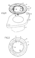
- the seal 2 shown in Figures 1 to 3 comprises a body flat annular 3 in the central part of which is formed an opening 4 delimited by an edge 5. Near the edge 5, is provided a sealing rib 6. This seal is intended to seal between two pipes 7 of an exhaust line, each pipe ending by a flange 8, in which are formed two openings 9 intended to allow the assembly of the two elements by bolts 10 shown schematically in phantom in Figure 3.
- the seal 2 has three legs 12 projecting from the edge 5, substantially perpendicular to the plane of the joint.
- Each leg 12 has, near its free end, a transverse fold 13 facing outward, delimiting an end zone 14 inclined at chamfer shape.
- the joint is positioned relative to a first element with engagement of lugs 12 in the tubing 7.
- the seal 12 is centered and retained, by support of the legs 12 against the tubing 7.
- the second element of the line can be positioned and then tightened on the first by the bolts 10.
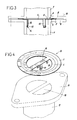
- FIG. 4 represents a seal 15, which constitutes a variant of the previous joint, in which the same elements are designated by the same references as before.
- This joint is intended to realize the seal against the flange 16 of a tube 17 having a central partition 18.
- the joint 3 has a diametrical central strip 19, corresponding to the partition 18, legs 20, 22 projecting from this central strip 19.
- the legs 20 arranged on either side of the central strip 19 are similar to the legs 12 of the seal described with reference in Figures 1 to 3. On the contrary, the legs 22 are straight legs, which are simple positioning tabs.
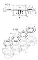
- FIG. 6 represents a seal 23 intended to equip a exhaust manifold, the multiple flange 24 of which is shown in drawing.
- This seal has several annular bodies 3 identical to that described with reference to Figures 1 to 3, connected to each other by bypasses 25.
- at least one tab 12 projects from the edge of each body 3 defining an opening 4 for the passage of gas from combustion.
- the invention provides a great improvement to the existing technique, providing a joint metal of simple structure, of a reduced cost price and having means ensuring its positioning and its retention on one of the elements an exhaust line, before assembling this element with a neighboring element.
Landscapes
- Engineering & Computer Science (AREA)
- General Engineering & Computer Science (AREA)
- Mechanical Engineering (AREA)
- Chemical & Material Sciences (AREA)
- Combustion & Propulsion (AREA)
- Exhaust Silencers (AREA)
- Gasket Seals (AREA)
Applications Claiming Priority (2)
| Application Number | Priority Date | Filing Date | Title |
|---|---|---|---|
| FR9801979A FR2774726B1 (fr) | 1998-02-12 | 1998-02-12 | Joint metallique d'etancheite pour ligne d'echappement de gaz de combustion de moteurs thermiques |
| FR9801979 | 1998-02-12 |
Publications (2)
| Publication Number | Publication Date |
|---|---|
| EP0939209A2 true EP0939209A2 (de) | 1999-09-01 |
| EP0939209A3 EP0939209A3 (de) | 2000-01-05 |
Family
ID=9523116
Family Applications (1)
| Application Number | Title | Priority Date | Filing Date |
|---|---|---|---|
| EP99420032A Withdrawn EP0939209A3 (de) | 1998-02-12 | 1999-02-11 | Metallischer Dichtungsring der Abgasleitung einer Brennkraftmaschine |
Country Status (2)
| Country | Link |
|---|---|
| EP (1) | EP0939209A3 (de) |
| FR (1) | FR2774726B1 (de) |
Cited By (6)
| Publication number | Priority date | Publication date | Assignee | Title |
|---|---|---|---|---|
| FR2867511A1 (fr) * | 2004-03-09 | 2005-09-16 | Faurecia Sys Echappement | Dispositif d'assemblage reversible d'un premier et d'un second troncon tubulaire d'une ligne d'echappement et joint d'etancheite pour un tel dispositif d'assemblage |
| DE10135335B4 (de) * | 2001-07-19 | 2009-10-01 | Elringklinger Ag | Flachdichtung |
| DE102008038052A1 (de) * | 2008-08-16 | 2010-02-18 | Elringklinger Ag | Dichtungsanordnung |
| DE102013104068A1 (de) * | 2013-04-22 | 2014-10-23 | Elringklinger Ag | Flachdichtung |
| CN105473909A (zh) * | 2013-08-01 | 2016-04-06 | 爱尔铃克铃尔股份公司 | 具有筛插入件的egr密封件以及制造方法 |
| US10520088B2 (en) | 2014-12-22 | 2019-12-31 | Nok Corporation | Metal gasket |
Families Citing this family (2)
| Publication number | Priority date | Publication date | Assignee | Title |
|---|---|---|---|---|
| FR2940363B1 (fr) * | 2008-12-22 | 2011-01-14 | Freudenberg Carl Kg | Joint de bloc moteur, notamment pour le montage d'un composant faiblement rigide sur ledit bloc moteur |
| WO2016177642A1 (en) * | 2015-05-01 | 2016-11-10 | Saint-Gobain Performance Plastics L+S GMBH | Seal rings |
Citations (5)
| Publication number | Priority date | Publication date | Assignee | Title |
|---|---|---|---|---|
| US3492834A (en) * | 1968-06-21 | 1970-02-03 | Arthur C Grantham | Seal means for refrigeration systems |
| US5044641A (en) * | 1989-10-31 | 1991-09-03 | Dana Corporation | Frictionless positioning grommet for engine gasket |
| US5333884A (en) * | 1990-10-25 | 1994-08-02 | Ishikawa Gasket Co., Ltd. | Gasket with auxiliary attaching mechanism |
| US5393108A (en) * | 1993-06-11 | 1995-02-28 | Indian Head Industries, Inc. | Spherical exhaust flange gasket with interference fit |
| US5524906A (en) * | 1994-07-18 | 1996-06-11 | Mascotech Tubular Products, Inc. | Gasket for exhaust system joint |
-
1998
- 1998-02-12 FR FR9801979A patent/FR2774726B1/fr not_active Expired - Fee Related
-
1999
- 1999-02-11 EP EP99420032A patent/EP0939209A3/de not_active Withdrawn
Patent Citations (5)
| Publication number | Priority date | Publication date | Assignee | Title |
|---|---|---|---|---|
| US3492834A (en) * | 1968-06-21 | 1970-02-03 | Arthur C Grantham | Seal means for refrigeration systems |
| US5044641A (en) * | 1989-10-31 | 1991-09-03 | Dana Corporation | Frictionless positioning grommet for engine gasket |
| US5333884A (en) * | 1990-10-25 | 1994-08-02 | Ishikawa Gasket Co., Ltd. | Gasket with auxiliary attaching mechanism |
| US5393108A (en) * | 1993-06-11 | 1995-02-28 | Indian Head Industries, Inc. | Spherical exhaust flange gasket with interference fit |
| US5524906A (en) * | 1994-07-18 | 1996-06-11 | Mascotech Tubular Products, Inc. | Gasket for exhaust system joint |
Cited By (7)
| Publication number | Priority date | Publication date | Assignee | Title |
|---|---|---|---|---|
| DE10135335B4 (de) * | 2001-07-19 | 2009-10-01 | Elringklinger Ag | Flachdichtung |
| FR2867511A1 (fr) * | 2004-03-09 | 2005-09-16 | Faurecia Sys Echappement | Dispositif d'assemblage reversible d'un premier et d'un second troncon tubulaire d'une ligne d'echappement et joint d'etancheite pour un tel dispositif d'assemblage |
| WO2005088093A1 (fr) * | 2004-03-09 | 2005-09-22 | Faurecia Systemes d'Echappement, Société Par Actions Simplifiée | Dispositif d'assemblage reversible d'un premier et d'un second troncon tubulaire d'une ligne d'echappement et joint d'etancheite pour un tel dispositif d'assemblage. |
| DE102008038052A1 (de) * | 2008-08-16 | 2010-02-18 | Elringklinger Ag | Dichtungsanordnung |
| DE102013104068A1 (de) * | 2013-04-22 | 2014-10-23 | Elringklinger Ag | Flachdichtung |
| CN105473909A (zh) * | 2013-08-01 | 2016-04-06 | 爱尔铃克铃尔股份公司 | 具有筛插入件的egr密封件以及制造方法 |
| US10520088B2 (en) | 2014-12-22 | 2019-12-31 | Nok Corporation | Metal gasket |
Also Published As
| Publication number | Publication date |
|---|---|
| FR2774726B1 (fr) | 2000-04-21 |
| FR2774726A1 (fr) | 1999-08-13 |
| EP0939209A3 (de) | 2000-01-05 |
Similar Documents
| Publication | Publication Date | Title |
|---|---|---|
| FR2568978A1 (fr) | Dispositif pour raccorder les extremites de gaines en tole metallique et connecteur d'angle pour ce dispositif | |
| EP0284466B1 (de) | Auspuffrohrverbindungsvorrichtung und mit dieser Vorrichtung ausgestatteter Verbrennungsmotor | |
| EP0624772B1 (de) | Wärmetauscher für Kraftfahrzeug | |
| EP0458700B1 (de) | Abgedichtete Verbindung zweier stumpf aneinanderstossender glatter Rohre | |
| EP2344830A1 (de) | Sammelplatte für einen wärmetauscher und wärmetauscher mit solch einer platte | |
| EP0939209A2 (de) | Metallischer Dichtungsring der Abgasleitung einer Brennkraftmaschine | |
| FR2886363A1 (fr) | Joint plat metallique a parties de liaison frangibles | |
| EP0403379A1 (de) | Verbindungsschelle für Auspuffleitungen | |
| FR2742857A1 (fr) | Plaque collectrice pour echangeur de chaleur | |
| EP2455697B1 (de) | Sammelkasten und entsprechender Wärmetauscher | |
| FR2472123A1 (fr) | Element d'etancheite de conduits, notamment pour moteur a combustion interne | |
| EP0298815A1 (de) | Elastische Kupplung | |
| WO2005090892A1 (fr) | Boite collectrice munie d’une tubulure de raccordement pour un echangeur de chaleur brase | |
| EP1957927B1 (de) | Verstärkter sammler für den sammelbehälter eines wärmetauschers und einen solchen sammler umfassender sammelbehälter | |
| EP4127541B1 (de) | Spannsystem zum verbinden von rohren mit einem bund und einer dichtung | |
| FR2621075A1 (fr) | Tuyau a bride d'extremite pour les gaz d'echappement d'un moteur de vehicule | |
| FR2882428A1 (fr) | Echangeur de chaleur a collecteur ameliore | |
| EP1724500A1 (de) | Dichtung mit befestigten Laschen | |
| FR2780153A1 (fr) | Echangeur de chaleur a tubes plats, en particulier pour vehicule automobile | |
| FR2751697A1 (fr) | Dispositif de fixation d'un pot d'echappement | |
| FR2883031A1 (fr) | Bride tole d'interface echappement | |
| FR2811748A1 (fr) | Tubulure pour echangeur de chaleur, notamment de vehicule automobile, et echangeur comportant cette tubulure | |
| EP2128548B1 (de) | Verteilerwärmetauscher und Verteilerkammer, insbesondere für Kraftfahrzeug | |
| FR2727493A1 (fr) | Dispositif et procede de raccordement etanche entre une bride munie d'au moins un tube et une piece | |
| WO1996017203A1 (fr) | Dispositif, procede et joint de raccordement etanche entre une bride munie d'au moins un tube et une piece |
Legal Events
| Date | Code | Title | Description |
|---|---|---|---|
| PUAI | Public reference made under article 153(3) epc to a published international application that has entered the european phase |
Free format text: ORIGINAL CODE: 0009012 |
|
| AK | Designated contracting states |
Kind code of ref document: A2 Designated state(s): AT BE CH DE DK ES FI FR GB IE IT LI LU NL PT SE |
|
| AX | Request for extension of the european patent |
Free format text: AL;LT;LV;MK;RO;SI |
|
| PUAL | Search report despatched |
Free format text: ORIGINAL CODE: 0009013 |
|
| AK | Designated contracting states |
Kind code of ref document: A3 Designated state(s): AT BE CH CY DE DK ES FI FR GB GR IE IT LI LU MC NL PT SE |
|
| AX | Request for extension of the european patent |
Free format text: AL;LT;LV;MK;RO;SI |
|
| 17P | Request for examination filed |
Effective date: 20000228 |
|
| AKX | Designation fees paid |
Free format text: AT BE CH DE DK ES FI FR GB IE IT LI LU NL PT SE |
|
| GRAG | Despatch of communication of intention to grant |
Free format text: ORIGINAL CODE: EPIDOS AGRA |
|
| 17Q | First examination report despatched |
Effective date: 20010731 |
|
| GRAG | Despatch of communication of intention to grant |
Free format text: ORIGINAL CODE: EPIDOS AGRA |
|
| GRAH | Despatch of communication of intention to grant a patent |
Free format text: ORIGINAL CODE: EPIDOS IGRA |
|
| GRAH | Despatch of communication of intention to grant a patent |
Free format text: ORIGINAL CODE: EPIDOS IGRA |
|
| STAA | Information on the status of an ep patent application or granted ep patent |
Free format text: STATUS: THE APPLICATION IS DEEMED TO BE WITHDRAWN |
|
| 18D | Application deemed to be withdrawn |
Effective date: 20020903 |