EP4127541B1 - Spannsystem zum verbinden von rohren mit einem bund und einer dichtung - Google Patents
Spannsystem zum verbinden von rohren mit einem bund und einer dichtung Download PDFInfo
- Publication number
- EP4127541B1 EP4127541B1 EP21720810.7A EP21720810A EP4127541B1 EP 4127541 B1 EP4127541 B1 EP 4127541B1 EP 21720810 A EP21720810 A EP 21720810A EP 4127541 B1 EP4127541 B1 EP 4127541B1
- Authority
- EP
- European Patent Office
- Prior art keywords
- washer
- clamping system
- collar
- annular
- seal
- Prior art date
- Legal status (The legal status is an assumption and is not a legal conclusion. Google has not performed a legal analysis and makes no representation as to the accuracy of the status listed.)
- Active
Links
- 239000000463 material Substances 0.000 claims description 13
- 239000002184 metal Substances 0.000 claims description 13
- 238000007789 sealing Methods 0.000 claims description 13
- 239000010445 mica Substances 0.000 claims description 9
- 229910052618 mica group Inorganic materials 0.000 claims description 9
- 239000011230 binding agent Substances 0.000 claims description 5
- 239000002131 composite material Substances 0.000 claims description 5
- OKTJSMMVPCPJKN-UHFFFAOYSA-N Carbon Chemical compound [C] OKTJSMMVPCPJKN-UHFFFAOYSA-N 0.000 claims description 4
- 239000010439 graphite Substances 0.000 claims description 4
- 229910002804 graphite Inorganic materials 0.000 claims description 4
- 229910052500 inorganic mineral Inorganic materials 0.000 claims description 3
- 239000011707 mineral Substances 0.000 claims description 3
- 239000002245 particle Substances 0.000 claims description 3
- 230000002787 reinforcement Effects 0.000 claims description 3
- 238000004026 adhesive bonding Methods 0.000 description 2
- 239000003292 glue Substances 0.000 description 2
- 230000037431 insertion Effects 0.000 description 2
- 238000003780 insertion Methods 0.000 description 2
- 239000007769 metal material Substances 0.000 description 2
- 239000010935 stainless steel Substances 0.000 description 2
- 229910001220 stainless steel Inorganic materials 0.000 description 2
- 210000002105 tongue Anatomy 0.000 description 2
- 239000011324 bead Substances 0.000 description 1
- 238000002485 combustion reaction Methods 0.000 description 1
- 239000000470 constituent Substances 0.000 description 1
- 238000005520 cutting process Methods 0.000 description 1
- 230000009977 dual effect Effects 0.000 description 1
- 238000005516 engineering process Methods 0.000 description 1
- 238000010438 heat treatment Methods 0.000 description 1
- 230000014759 maintenance of location Effects 0.000 description 1
- 238000004519 manufacturing process Methods 0.000 description 1
- 238000007493 shaping process Methods 0.000 description 1
- 125000006850 spacer group Chemical group 0.000 description 1
- 238000003466 welding Methods 0.000 description 1
Images


Classifications
-
- F—MECHANICAL ENGINEERING; LIGHTING; HEATING; WEAPONS; BLASTING
- F16—ENGINEERING ELEMENTS AND UNITS; GENERAL MEASURES FOR PRODUCING AND MAINTAINING EFFECTIVE FUNCTIONING OF MACHINES OR INSTALLATIONS; THERMAL INSULATION IN GENERAL
- F16L—PIPES; JOINTS OR FITTINGS FOR PIPES; SUPPORTS FOR PIPES, CABLES OR PROTECTIVE TUBING; MEANS FOR THERMAL INSULATION IN GENERAL
- F16L23/00—Flanged joints
- F16L23/16—Flanged joints characterised by the sealing means
- F16L23/18—Flanged joints characterised by the sealing means the sealing means being rings
- F16L23/22—Flanged joints characterised by the sealing means the sealing means being rings made exclusively of a material other than metal
-
- F—MECHANICAL ENGINEERING; LIGHTING; HEATING; WEAPONS; BLASTING
- F16—ENGINEERING ELEMENTS AND UNITS; GENERAL MEASURES FOR PRODUCING AND MAINTAINING EFFECTIVE FUNCTIONING OF MACHINES OR INSTALLATIONS; THERMAL INSULATION IN GENERAL
- F16L—PIPES; JOINTS OR FITTINGS FOR PIPES; SUPPORTS FOR PIPES, CABLES OR PROTECTIVE TUBING; MEANS FOR THERMAL INSULATION IN GENERAL
- F16L23/00—Flanged joints
- F16L23/04—Flanged joints the flanges being connected by members tensioned in the radial plane
- F16L23/08—Flanged joints the flanges being connected by members tensioned in the radial plane connection by tangentially arranged pin and nut
-
- F—MECHANICAL ENGINEERING; LIGHTING; HEATING; WEAPONS; BLASTING
- F16—ENGINEERING ELEMENTS AND UNITS; GENERAL MEASURES FOR PRODUCING AND MAINTAINING EFFECTIVE FUNCTIONING OF MACHINES OR INSTALLATIONS; THERMAL INSULATION IN GENERAL
- F16L—PIPES; JOINTS OR FITTINGS FOR PIPES; SUPPORTS FOR PIPES, CABLES OR PROTECTIVE TUBING; MEANS FOR THERMAL INSULATION IN GENERAL
- F16L21/00—Joints with sleeve or socket
- F16L21/08—Joints with sleeve or socket with additional locking means
-
- F—MECHANICAL ENGINEERING; LIGHTING; HEATING; WEAPONS; BLASTING
- F16—ENGINEERING ELEMENTS AND UNITS; GENERAL MEASURES FOR PRODUCING AND MAINTAINING EFFECTIVE FUNCTIONING OF MACHINES OR INSTALLATIONS; THERMAL INSULATION IN GENERAL
- F16L—PIPES; JOINTS OR FITTINGS FOR PIPES; SUPPORTS FOR PIPES, CABLES OR PROTECTIVE TUBING; MEANS FOR THERMAL INSULATION IN GENERAL
- F16L17/00—Joints with packing adapted to sealing by fluid pressure
- F16L17/02—Joints with packing adapted to sealing by fluid pressure with sealing rings arranged between outer surface of pipe and inner surface of sleeve or socket
- F16L17/04—Joints with packing adapted to sealing by fluid pressure with sealing rings arranged between outer surface of pipe and inner surface of sleeve or socket with longitudinally split or divided sleeve
-
- F—MECHANICAL ENGINEERING; LIGHTING; HEATING; WEAPONS; BLASTING
- F16—ENGINEERING ELEMENTS AND UNITS; GENERAL MEASURES FOR PRODUCING AND MAINTAINING EFFECTIVE FUNCTIONING OF MACHINES OR INSTALLATIONS; THERMAL INSULATION IN GENERAL
- F16L—PIPES; JOINTS OR FITTINGS FOR PIPES; SUPPORTS FOR PIPES, CABLES OR PROTECTIVE TUBING; MEANS FOR THERMAL INSULATION IN GENERAL
- F16L21/00—Joints with sleeve or socket
- F16L21/06—Joints with sleeve or socket with a divided sleeve or ring clamping around the pipe-ends
- F16L21/065—Joints with sleeve or socket with a divided sleeve or ring clamping around the pipe-ends tightened by tangentially-arranged threaded pins
-
- F—MECHANICAL ENGINEERING; LIGHTING; HEATING; WEAPONS; BLASTING
- F16—ENGINEERING ELEMENTS AND UNITS; GENERAL MEASURES FOR PRODUCING AND MAINTAINING EFFECTIVE FUNCTIONING OF MACHINES OR INSTALLATIONS; THERMAL INSULATION IN GENERAL
- F16L—PIPES; JOINTS OR FITTINGS FOR PIPES; SUPPORTS FOR PIPES, CABLES OR PROTECTIVE TUBING; MEANS FOR THERMAL INSULATION IN GENERAL
- F16L23/00—Flanged joints
- F16L23/16—Flanged joints characterised by the sealing means
- F16L23/18—Flanged joints characterised by the sealing means the sealing means being rings
Definitions
- the presentation relates to a clamping system for connecting a first and a second tube whose facing ends have bearing surfaces projecting relative to the cylindrical exterior surface of said tubes, the system comprising a collar and a seal, the collar being able to be tightened around the bearing surfaces of the tubes.
- This device is particularly suitable for clamping two tubes fitted together and having radially projecting surfaces serving as support for a clamp which comprises a recess capable of housing these radially projecting surfaces, the closed annular seal itself having a shape suitable for these protruding surfaces.
- such a seal can be made from a stainless steel type metal, as well as the collar belt.
- the presentation aims to remedy at least substantially the aforementioned drawbacks.
- the presentation concerns a clamping system for connecting a first and a second tube whose facing ends have bearing surfaces projecting relative to the cylindrical exterior surface of said tubes, the system comprising a collar which can be tightened and a seal, the collar comprising a belt capable of cooperating with said bearing surfaces by its interior periphery delimiting a recess in which the bearing surfaces can be inserted, the seal being supported by the collar in the untightened state of the latter and comprising an annular sealing part, which comprises a first washer and a second washer fixed to the first washer, the first washer carrying retaining tabs which cooperate with the second washer to retain said second washer relative to the first washer.
- the first washer is metallic.
- the retaining tabs are cut into the first washer.
- the first washer carries support tabs by which said first washer and said second washer are supported relative to the collar.
- At least some of the support legs are formed in one piece with the first washer.
- At least some of the retaining tabs are formed in the support tabs.
- the retaining tabs are formed by parts of the support tabs projecting radially inwards, in particular by wings folded on longitudinal edges of the support tabs or tabs cut out in the support tabs and folded inwards.
- the first washer has a stamped frustoconical surface and the second washer is formed in a plane ring, deformed to match the frustoconical shape of the frustoconical surface.
- the second washer is formed from a composite material.
- the second washer is formed from mica-based material.
- the second washer comprises mineral particles, in particular mica or graphite, and a binder.
- the second washer includes a frame, in particular a metal frame.
- the first washer has an annular bulge on a first face of said first washer and the second washer is placed against said first face.
- the second washer has an annular bulge on a first face of said second washer and said first faces of the first washer and the second washer are placed against each other, so that the annular bulges are in contact.
- the second washer also has an annular bulge on its second face and said annular bulges of the second washer optionally delimit an annular space between them.
- the annular sealing part further comprises a second additional washer fixed to the first washer, so that the first washer is located between the second washer and the second additional washer.
- the seal of the clamping system therefore comprises two washers which are fixed together by retaining lugs which the first washer carries.
- the two washers are fixed together by mechanical means, which do not alter over time and are simple to implement.
- the retaining tabs may not require any material external to the first washer and be made directly with it. In particular, it may not be necessary to attach the two washers using glue.
- the retaining tabs are used to fix the two washers together, while possibly allowing them to be slight movements between the two washers, thus facilitating their adjustment when tightening, to optimize sealing.
- All of these two washers can be worn relative to the collar using a suitable configuration of the seal.
- the part necessary for sealing namely the first washer and the second washer, can be easily shaped so as to meet the need for sealing, taking into account the tightening constraints and the temperature levels concerned.
- the second washer may be metallic or comprise a material adapted to maintain elastic deformability at high temperatures and to contribute to sealing over wide temperature and stress ranges, in particular a mica-based material.
- the seal may be light, the first washer part providing its strength and mechanical resistance, the non-metallic base part contributing to its effectiveness, particularly for high temperature and pressure ranges.
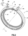
- FIG. 1 shows a clamp 10 comprising a belt 12 whose ends are raised radially so as to form clamping lugs 12A and 12B respectively.
- a tightening screw 14 With the tightening tabs 12A and 12B.
- the barrel 14B of the screw passes through the holes in the clamping tabs, its head 14A cooperating with the tab 12A and the opposite end being provided with a nut 14C cooperating with the tab 12B in this case via a spacer 14D.
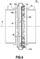
- the belt 12 has an internal recess 15 (better visible on the Figure 4 ) provided between two sides, respectively 12C and 12D, of this belt.
- a seal 20 is placed inside the belt.
- the clamping system is used to connect two tubes 1 and 2 whose ends are provided with bearing surfaces 1A and 2A. To connect the tubes, their ends are brought together until they are axially in the recess 15, and the diameter of the belt is reduced so that the sides 12C and 12D tighten against the bearing surfaces 1A and 2A.
- the bearing surfaces 1A and 2A are formed on radial flanges which the ends of the tubes 1 and 2 have.
- the seal 20 is arranged inside the collar.
- the front surfaces 1'A and 2'A of the ends of the tubes 1A and 2A are placed on either side of an annular sealing part 21 presented by the seal 20.
- the forward direction for the tube 1 or 2 is the direction going towards the other tube 2 or 1 when their ends are brought together to assemble the tubes.
- the bearing surfaces 1A and 2A are formed on the rear faces of the radial flanges present at the ends of the tubes.
- the backward direction is obviously the opposite direction.
- the direction towards the inside is that which goes towards axis A of the belt.
- the outward direction is opposite.
- This annular sealing part comprises a first washer 22 and a second washer 24 fixed to the first washer.
- the annular sealing part comprises the first washer 22, the second washer 24 disposed on a first face of the first washer and a second additional washer 26 disposed on the other face of the first washer.
- the first washer 22 is sandwiched between the second washers 24 and 26.
- the first washer 22 can be made from the same metal as the belt 12, for example stainless steel.
- the second washer(s) 24, 26 may be formed from metal, or may have a non-metallic base, in particular being formed from a composite material. They can be formed from a mica-based material. They can be formed from the same material or from different materials, for example one made of metal, the other made of composite material, for example based on mica.
- the second washer(s) may comprise mineral particles, in particular mica or graphite, and a binder. The two washers may or may not have the same thickness, whether or not they are made of the same material.
- the second washer(s) may comprise an armature, in particular a metallic armature, supporting non-metallic material, in particular a composite material based on mica or graphite.
- the reinforcement can be a thin metal mesh.
- the indication that the washer 24 or 26 is "non-metallic based" means that this washer does not contain metal or that, if it contains metal, for example a metal frame, the metal only represents by mass a minority part of this washer, for example the mass of metal does not represent more than 40% of that of the washer, in particular not more than 20 or 30%.
- the second washer(s) 24 and 26 are carried by the first washer 22.
- this first washer 22 carries support tabs by which the first washer and the second washer are supported relative to the collar 10.
- the seal is thus pre-assembled in the belt, that is to say, before the positioning the collar on the tubes and tightening it, the seal is carried by the collar so that the collar and seal can be handled as a set.
- the first washer can also carry support tabs used for pre-assembly of the collar equipped with the washer on one of the tubes to be assembled.
- the assembly formed by the collar and the seal can be placed at the end of one of the tubes and remain in place at this end, before positioning the end of the other tube and tightening the collar.
- the same tabs can have the dual function of serving for pre-assembly of the seal in the belt and for pre-assembly of the assembly formed by the collar and the seal at the end of one of the tubes.
- These support tabs are carried by the external periphery (far from the axis A of the belt), of the first washer 22.
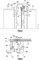
- the support tabs 30 have ends 30A curved into a hook so as to be able to hang on the edge 13 of the side 12C of the belt 12. Between their connection zone to the external periphery 22' of the first washer 22 and this hook 30A, these support tabs 30 have an axial section 30B which extends substantially axially, that is to say substantially parallel to the axis A.
- this axial section 30B has, on the one hand, a hooking tab 30C which is cut out in the axial section 30B and folded radially inwards, extending towards its free end, in the direction going from the hook 30A to the external periphery 22' of the first washer 22.
- This tongue 30C serves to grip the washer on the bearing surface 1A of the tube 1 to retain the collar pre-assembled at the end of this tube.
- the orientation of these tabs 30C prevents the tube from being able to be released from the washer in the rearward direction for this tube 1, according to the arrow R1 indicated on the Figure 4 .
- the support legs 30 have wings 30D which, from the longitudinal edges of the axial sections 30B, are folded radially outwards, that is to say so as to move away from the axis A Furthermore, these wings 30D have a retaining edge 30D' directed towards the internal face of the hook 30A and therefore towards the internal face of the flank 12C of the belt 12 when the seal is pre-assembled in the washer. These retaining edges 30D' are spaced from the internal faces of the hooks 30A. The edge 13 of the side 12C is housed in the space thus provided between the hook 30A and the retaining edge 30D. This makes it possible to maintain the first washer 22 relative to the collar belt by retaining it in both axial directions.
- the support tabs also comprise support tabs 32 which also have hooks 32A at their free ends opposite their areas of attachment to the external periphery 22' of the washer 22.
- These support tabs 32 also include axial sections 32B which extend substantially axially between the attachment of these tabs to the washer 22 and the hooks 32A.
- These support tabs 32 also have hooking tabs 32C similar to the tabs 30C previously described.
- these support legs 32 also include wings 32D which are however oriented in the opposite direction to the aforementioned wings 30D. Indeed, the wings 32D are folded radially inwards from the longitudinal edges of the axial sections 32B. These wings 32D have longitudinal edges 32D' which contribute to the pre-mounted retention of the collar on the end of the tube 1 by retaining the washer relative to the tube with respect to radial deflections.
- the first washer still has support legs 34 which, as seen on the figures 1 And 3 , have hooks 34A at their free ends opposite the external periphery 22' of the washer 22 and axial sections which extend from this washer to these hooks.
- These support tabs 34 serve to angularly position the washer relative to the belt, the hooks 34A being engaged in notches 13A presented by the edge 13 of the side 12C of the belt.
- the support tabs 30 and the support tabs 32 are arranged alternately on the external periphery of the washer 22. These tabs 30 and 32 serve to hook onto the edge 13 of the side 12C of the belt 12 by preventing the seal to move relative to the belt in the opposite direction to the direction R1 indicated on the Figure 4 .
- the 30D wings serve to retain the washer relative to the belt by limiting its movement in direction R1 relative to the belt.
- These tabs, as well as the tabs 32 also have tabs 30C or 32C used to retain the end of the tube inside the washer.
- the legs 32 also have wings 32D used to center the tube relative to the washer.
- the support legs 30 and 32 are formed in one piece with the first washer.
- this first washer is formed in a single piece from a strip, by cutting, stamping and folding.
- the first washer 22 and the second washers 24 and 26 are substantially flat. Indeed, the front faces 1'A and 2'A flanges on which are formed the bearing surfaces of the tubes 1 and 2 on which are oriented radially.
- the collar can be pre-assembled on tubes whose bearing surfaces are frustoconical.
- the first washer 122 may have a frustoconical surface, in particular a stamped frustoconical surface.
- the seal 120 with the washer 122 and support tabs 30, 32 and 34, similar to the tabs previously described.
- This belt 112 is similar to the belt 12, except that its sides 112C and 112B can be inclined like the branches of a V, adapted to the flare of the tubes 101 and 102.
- the support surface 101A of the tube 101 has a frustoconical shape forming a flare
- the bearing surface 102A of the tube 102 has a front face 102'A, which also forms a frustoconical surface so as to be adapted to the aforementioned flare.
- the bearing surface 102A formed at the rear in the direction R2 with respect to the frustoconical portion 102'A is also frustoconical in the opposite direction, substantially parallel to the flank 112B of the belt 112.
- the first washer has a stamped frustoconical surface 122A, adapted to the shapes of the surfaces 101'A and 102'A of the tubes whose connection must be sealed using the seal 120.
- the second washer 124 is formed in a plane ring which is deformed to match the frustoconical shape of the frustoconical surface of the first washer 122.
- this washer 124 cannot always be stamped. It may be interesting to form it from a flat plate for manufacturing cost reasons. However, to a certain extent, an initially planar (fabricated flat) washer with a non-metallic base can be deformed to conform to the frustoconical shape of the surface 122A of the washer 122.
- the angle ⁇ formed by the aforementioned frustoconical surfaces of the tubes with respect to the direction perpendicular to the axis A is for example of the order of 20 degrees maximum for an initially flat washer with a non-metallic base.
- the second washer 24 can, unlike the first washer 22, be purely annular, being devoid of fixing lugs, support or others.
- the second washer is carried by the first washer 22.
- the second washer 24 is fixed to the first washer 22 by retaining tabs which the latter carries.
- the second washer 24 can be supported by the first washer 22 by purely mechanical means not using an external material such as glue.
- the first washer 22 has retaining tabs 36 which are formed by cutouts of this washer slightly straightened axially to form tongues whose free ends are oriented towards the axis A. These retaining tabs 36 thus serve to wedge and retain the second washer 24 by cooperating with its external radial edge 24A.
- the first washer 22 has retaining tabs 38 which are similar to the retaining tabs 36 but are oriented on the other side axially to retain the second additional washer 26 located on the other face of the washer 22.
- the retaining tabs 36 or 38 retain the washers 24 or 26 by their external radial edges.
- the support tabs of the first washer may include retaining tabs for retaining the second washer relative to the first washer.
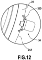
- the first washer 22 with one of its support legs 32 and one of its support legs 34.
- the Figure 10 also shows the second washer 24 whose external diameter is almost equal to the external diameter of the first washer 22, being very slightly less than it.
- the outer edge 24A of the second washer 24 extends substantially to the circle delimiting the outer edge of the first washer 22, between the support legs.
- the support tab 34 or more precisely its axial section 34B, has a hooking tab 34C which forms a retaining tab for the second washer 24. This retaining tab 34C is cut out from the axial section 34B by being attached to it by its end close to the hook 34A, while its opposite end is free.
- the retaining tab 34C can be cut in a circumferentially central region of the axial section 34B or on the contrary on an edge longitudinal of the latter.
- the retaining tab 34C is bent radially inward.
- the free end of the retaining tab 34C is located radially further inwards than the outer edge 24A of the second washer 24, which allows it to perform its function as a retaining tab.
- the edge 24A of the second washer 24 and/or the retaining tab 34C can be elastically deflected to allow the insertion of the outer edge of the second washer 24 under the free end of the tab hooking 34C.
- the wings 32D of the support tabs 32 can also act as retaining tabs for the second washer 24.
- outer edge 24A of the second washer 24 reaches radially under the wings 32D, in the space provided between the edges of these wings distant from the hook 32A and the outer edge of the annular part of the first washer 22.
- outer edge 24A of the second washer can be elastically deflected to allow the insertion of this outer edge into this space, when assembling the two washers.
- the first washer 22 may have an annular bulge or, in general, an annular relief giving it a capacity for axial deformation.
- annular bulge or, in general, an annular relief giving it a capacity for axial deformation.
- the second washer 24 or the second additional washer 26 can for its part be perfectly flat. It can also have an annular bulge 24A, in particular whose convexity can be reversed relative to those of the annular bulge 22A of the washer 22 and whose diametric dimensions correspond to those of the bulge 22A.
- the washer 24 when the washer 24 is assembled to the washer 22, their respective bulges can therefore be in contact via their convex faces, which is a way of allowing axial deformation of the washers under the clamping forces in the areas of the bulges to ensure a good seal.
- the washer 26 can for its part have an annular bulge 26A which can have a convexity of a direction similar to that of the annular bulge 22A so as to "fit" partly into this bulge, in which case these are rather the zones of the washers other than the bulges which may be deformed under tightening forces. These bulges can also be in the opposite direction.
- the second washer 124 is in fact formed of two elementary washers, respectively 123 and 123' fixed together, for example by gluing or by mechanical fixing using retaining tabs, for example similar to the tabs retainer 36 or 38 mentioned above.
- Each of these elementary washers 123 and 123' has an annular bulge, respectively 123A and 123B.
- the washer 124 has an annular bulge not only on its first face facing the first washer 22, but also on the second opposite face.
- the annular bulges 123A and 123B are arranged on the same diametric dimensions so as to provide an annular space 124' between them.
- the first washer 22 has an annular bulge 22A projecting on its first face against which the washer 124 is placed, so that the annular bulges 22A and 123A are arranged one against the other.
- the first washer 22 may have a wave or deformation forming a slight fold so that the inner and outer radial edges of the first washer are slightly spaced axially. This is what we see for example on the Figure 7 , on which the first washer 22 has such a slight fold 22B.
- the second washers 24 and 26 arranged on either side of the first washer 22 can be initially flat and be deformed to adapt to this fold when tightening the collar, or else initially present such folds.
- the reliefs, folds or bulges of the second washer can be produced by any appropriate means, for example by hot shaping, in particular when the material in which this washer is made includes a thermoformable binder.
- the thickness of the first washer 22, measured axially between the two faces of the latter in a zone in which no bulge is present, is for example of the order of 0.2 mm to 0.8 mm, in particular of the order of 0.2 mm to 0.4 mm.
- the thickness of the second washer, measured in the same way, can be 50% to 200%, in particular 120% to 200%, of the thickness of the first washer.
Claims (16)
- Klemmsystem für die Verbindung eines ersten und eines zweiten Rohrs (1, 2), deren einander zugewandte Enden Anlageflächen (1'A, 2'A) aufweisen, die in Bezug auf die äußere zylindrische Oberfläche der Rohre wegragen, wobei das System eine Schelle (10), die zusammengeklemmt werden kann, und eine Dichtung (20) umfasst, wobei die Schelle einen Gurtring (12) beinhaltet, der dazu geeignet ist, mit den Anlageflächen durch seinen Innenumfang zusammenzuwirken, der eine Aussparung (15) begrenzt, in welche die Anlageflächen eingesetzt werden können, wobei die Dichtung von der Schelle in deren nicht zusammengeklemmtem Zustand getragen wird und einen ringförmigen Dichtabschnitt (21) umfasst, der eine erste Unterlegscheibe (22, 122) und eine zweite Unterlegscheibe (24, 124) umfasst, die an der ersten Unterlegscheibe befestigt ist, wobei die erste Unterlegscheibe (22, 122) Sicherungslaschen (36, 38, 34C, 32D) trägt, die mit der zweiten Unterlegscheibe (24, 124) zusammenwirken, um die zweite Unterlegscheibe in Bezug auf die erste Unterlegscheibe zu sichern.
- Klemmsystem nach Anspruch 1, wobei die erste Unterlegscheibe (22, 122) aus Metall ist.
- Klemmsystem nach Anspruch 1 oder 2, wobei die Sicherungslaschen (36, 38, 34C, 32D) in die erste Unterlegscheibe (22, 122) eingeschnitten sind.
- Klemmsystem nach einem der Ansprüche 1 bis 3, wobei die erste Unterlegscheibe (22, 122) Haltelaschen (30, 32, 34) trägt, durch welche die erste Unterlegscheibe und die zweite Unterlegscheibe (24, 124) in Bezug auf die Schelle gehalten werden.
- Klemmsystem nach Anspruch 4, wobei zumindest einige der Haltelaschen (30, 32, 34) einstückig mit der ersten Unterlegscheibe (22, 122) ausgebildet sind.
- Klemmsystem nach Anspruch 4 oder 5, wobei zumindest einige der Sicherungslaschen (36, 38, 34C, 32D) in den Haltelaschen (30, 32, 34) ausgebildet sind.
- Klemmsystem nach Anspruch 6, wobei zumindest einige der Sicherungslaschen (34C, 32D) durch Abschnitte der Haltelaschen (32, 34) ausgebildet sind, die nach innen radial wegragen, insbesondere durch Flügel (32D), die über die Längskanten der Haltelaschen (32) zurückgefaltet sind, oder Zungen (34C), die in die Haltelaschen (34) eingeschnitten und nach innen gefaltet sind.
- Klemmsystem nach einem der Ansprüche 1 bis 7, wobei die erste Unterlegscheibe (22, 122) eine kegelstumpfförmige eingetiefte Oberfläche aufweist und die zweite Unterlegscheibe (24, 124) als ein flacher Ring geformt ist, der verformt wird, um sich an die kegelstumpfförmige Form der kegelstumpfförmigen Oberfläche anzupassen.
- Klemmsystem nach einem der Ansprüche 1 bis 8, wobei die zweite Unterlegscheibe (24, 124) aus einem Verbundmaterial gebildet ist.
- Klemmsystem nach einem der Ansprüche 1 bis 9, wobei die zweite Unterlegscheibe (24, 124) aus einem Material auf Basis von Mica gebildet ist.
- Klemmsystem nach einem der Ansprüche 1 bis 10, wobei die zweite Unterlegscheibe (24, 124) mineralische Partikel, insbesondere aus Mica oder aus Graphit, und ein Bindemittel umfasst.
- Klemmsystem nach einem der Ansprüche 1 bis 11, wobei die zweite Unterlegscheibe (24, 124) eine Bewehrung, insbesondere eine metallische Bewehrung umfasst.
- Klemmsystem nach einem der Ansprüche 1 bis 12, wobei die erste Unterlegscheibe (22, 122) eine ringförmige Ausbauchung (22A) auf einer ersten Seite der ersten Unterlegscheibe aufweist und die zweite Unterlegscheibe (24, 124) gegen die erste Seite angeordnet ist.
- Klemmsystem nach Anspruch 13, wobei die zweite Unterlegscheibe (24, 124) eine ringförmige Ausbauchung (24A, 123A) auf einer ersten Seite der zweiten Unterlegscheibe aufweist und die ersten Seiten der ersten Unterlegscheibe und der zweiten Unterlegscheibe gegeneinander angeordnet sind, sodass die ringförmigen Ausbauchungen in Kontakt sind.
- Klemmsystem nach Anspruch 14, wobei die zweite Unterlegscheibe (24, 124) gleichermaßen eine ringförmige Ausbauchung (123B) auf ihrer zweiten Seite aufweist und die ringförmigen Ausbauchungen der zweiten Unterlegscheibe optional zwischeneinander einen ringförmigen Raum (124') begrenzen.
- Klemmsystem nach einem der Ansprüche 1 bis 15, wobei der ringförmige Dichtabschnitt (21) ferner eine zusätzliche zweite Unterlegscheibe (26) umfasst, die an der ersten Unterlegscheibe (22, 122) so befestigt ist, dass die erste Unterlegscheibe sich zwischen der zweiten Unterlegscheibe und der zusätzlichen zweiten Unterlegscheibe befindet.
Applications Claiming Priority (2)
| Application Number | Priority Date | Filing Date | Title |
|---|---|---|---|
| FR2003382A FR3108961B1 (fr) | 2020-04-03 | 2020-04-03 | Système de serrage pour le raccordement de tubes, comprenant un collier et un joint d’étanchéité |
| PCT/FR2021/050544 WO2021198604A1 (fr) | 2020-04-03 | 2021-03-26 | Systeme de serrage pour le raccordement de tubes, comprenant un collier et un joint d'etancheite |
Publications (2)
| Publication Number | Publication Date |
|---|---|
| EP4127541A1 EP4127541A1 (de) | 2023-02-08 |
| EP4127541B1 true EP4127541B1 (de) | 2024-04-24 |
Family
ID=70804823
Family Applications (2)
| Application Number | Title | Priority Date | Filing Date |
|---|---|---|---|
| EP21720810.7A Active EP4127541B1 (de) | 2020-04-03 | 2021-03-26 | Spannsystem zum verbinden von rohren mit einem bund und einer dichtung |
| EP21720809.9A Active EP4127540B1 (de) | 2020-04-03 | 2021-03-26 | Spannsystem zum verbinden von rohren mit einem bund und einer dichtung |
Family Applications After (1)
| Application Number | Title | Priority Date | Filing Date |
|---|---|---|---|
| EP21720809.9A Active EP4127540B1 (de) | 2020-04-03 | 2021-03-26 | Spannsystem zum verbinden von rohren mit einem bund und einer dichtung |
Country Status (7)
| Country | Link |
|---|---|
| US (2) | US20230184356A1 (de) |
| EP (2) | EP4127541B1 (de) |
| JP (3) | JP2023520512A (de) |
| KR (3) | KR20220156967A (de) |
| CN (3) | CN115335626A (de) |
| FR (2) | FR3108961B1 (de) |
| WO (2) | WO2021198604A1 (de) |
Families Citing this family (1)
| Publication number | Priority date | Publication date | Assignee | Title |
|---|---|---|---|---|
| DE102022113803A1 (de) * | 2022-06-01 | 2023-12-07 | Norma Germany Gmbh | Montagering und Rohrverbindungssystem |
Family Cites Families (16)
| Publication number | Priority date | Publication date | Assignee | Title |
|---|---|---|---|---|
| US4185858A (en) * | 1978-06-28 | 1980-01-29 | The United States Of America As Represented By The Secretary Of The Air Force | Secondary seal for tubing joined via V-band couplings |
| DE19534437C2 (de) * | 1995-09-16 | 2000-09-21 | Daimler Chrysler Ag | Schelle zur Verbindung von zwei rohrförmigen Leitungsteilen |
| AU2002313651A1 (en) * | 2001-06-29 | 2003-03-03 | Breeze-Torca Products, Llc | Clamp for joining tubular bodies |
| FR2833065B1 (fr) | 2001-12-05 | 2004-09-03 | Caillau Ets | Systeme de serrage pour le raccordement etanche de deux tubes ayant des surfaces d'appui |
| FR2963404B1 (fr) * | 2010-07-27 | 2014-02-07 | Caillau Ets | Systeme de serrage pour le raccordement et le pre-montage d'un premier et d'un deuxieme tube |
| FR3025581B1 (fr) * | 2014-09-04 | 2017-03-24 | Caillau Ets | Systeme pour le raccordement de deux tubes |
| FR3048468B1 (fr) * | 2016-03-07 | 2018-04-06 | Etablissements Caillau | Systeme de serrage comprenant un collier et des clips individuels de pre-montage |
| FR3049997B1 (fr) | 2016-04-12 | 2018-05-04 | Etablissements Caillau | Dispositif de serrage comprenant un collier de serrage et un manchon |
| FR3057047B1 (fr) * | 2016-10-04 | 2019-05-10 | Etablissements Caillau | Systeme de serrage a position angulaire controlee pour le raccordement de deux tubes |
| FR3057918B1 (fr) * | 2016-10-26 | 2018-11-23 | Etablissements Caillau | Dispositif de serrage comprenant un collier de serrage a temoin de positionnement |
| DE102017121994A1 (de) * | 2017-09-22 | 2019-03-28 | Norma Germany Gmbh | Profilschelle mit Dichtelement |
| DE102017222383A1 (de) * | 2017-12-11 | 2019-06-13 | Audi Ag | Anordnung und Verfahren zum Verbinden fluidleitender Bauteile, insbesondere im Abgasstrang eines Kraftfahrzeugs |
| FR3080666B1 (fr) * | 2018-04-26 | 2020-05-08 | Etablissements Caillau | Systeme de serrage a pattes rabattables pour le raccordement de tubes |
| FR3088097B1 (fr) * | 2018-11-07 | 2020-11-27 | Caillau Ets | Collier de serrage a doigt de retenue rabattable |
| FR3103233B1 (fr) * | 2019-11-20 | 2021-11-26 | Caillau | Collier de serrage |
| ES2937419T3 (es) * | 2020-04-03 | 2023-03-28 | Caillau | Sistema de ajuste para la conexión de tubos, que comprende una abrazadera y una arandela que lleva patillas de soporte |
-
2020
- 2020-04-03 FR FR2003382A patent/FR3108961B1/fr active Active
- 2020-05-19 FR FR2005095A patent/FR3108960B1/fr active Active
-
2021
- 2021-03-26 JP JP2022560197A patent/JP2023520512A/ja active Pending
- 2021-03-26 US US17/916,083 patent/US20230184356A1/en active Pending
- 2021-03-26 JP JP2022560196A patent/JP2023520511A/ja active Pending
- 2021-03-26 CN CN202180023974.XA patent/CN115335626A/zh active Pending
- 2021-03-26 CN CN202180023943.4A patent/CN115380185A/zh active Pending
- 2021-03-26 EP EP21720810.7A patent/EP4127541B1/de active Active
- 2021-03-26 WO PCT/FR2021/050544 patent/WO2021198604A1/fr active Application Filing
- 2021-03-26 WO PCT/FR2021/050543 patent/WO2021198603A1/fr active Application Filing
- 2021-03-26 KR KR1020227038604A patent/KR20220156967A/ko active Search and Examination
- 2021-03-26 KR KR1020227038603A patent/KR20220152400A/ko unknown
- 2021-03-26 EP EP21720809.9A patent/EP4127540B1/de active Active
- 2021-03-26 US US17/916,107 patent/US20230160507A1/en active Pending
- 2021-03-29 JP JP2021054567A patent/JP2021169859A/ja active Pending
- 2021-04-02 KR KR1020210043344A patent/KR20210124070A/ko active Search and Examination
- 2021-04-06 CN CN202110366486.0A patent/CN113494646A/zh active Pending
Also Published As
| Publication number | Publication date |
|---|---|
| CN115335626A (zh) | 2022-11-11 |
| US20230184356A1 (en) | 2023-06-15 |
| EP4127541A1 (de) | 2023-02-08 |
| US20230160507A1 (en) | 2023-05-25 |
| EP4127540A1 (de) | 2023-02-08 |
| EP4127540B1 (de) | 2024-04-24 |
| FR3108961B1 (fr) | 2022-08-26 |
| WO2021198603A1 (fr) | 2021-10-07 |
| KR20220156967A (ko) | 2022-11-28 |
| JP2021169859A (ja) | 2021-10-28 |
| WO2021198604A1 (fr) | 2021-10-07 |
| FR3108960A1 (fr) | 2021-10-08 |
| FR3108961A1 (fr) | 2021-10-08 |
| FR3108960B1 (fr) | 2022-04-08 |
| JP2023520512A (ja) | 2023-05-17 |
| KR20220152400A (ko) | 2022-11-15 |
| CN113494646A (zh) | 2021-10-12 |
| CN115380185A (zh) | 2022-11-22 |
| KR20210124070A (ko) | 2021-10-14 |
| JP2023520511A (ja) | 2023-05-17 |
Similar Documents
| Publication | Publication Date | Title |
|---|---|---|
| EP2598785B1 (de) | Klemmsystem zur verbindung und vormontage eines ersten und zweiten rohrs | |
| EP3217059B1 (de) | Spannanordnung mit einer spannschelle und einzelne vormontageclips | |
| EP3306164B1 (de) | Spannsystem in kontrollierter winkelposition für anschluss von zwei rohren | |
| EP3901507B1 (de) | Spannsystem für die verbindung von rohren, das eine schelle und eine unterlegscheibe mit haltebügeln umfasst | |
| EP2156088B1 (de) | Spannvorrichtung | |
| EP3189261B1 (de) | Kopplungssystem für zwei rohre | |
| WO2003048624A1 (fr) | Systeme de serrage pour le raccordement etanche de deux tubes ayant des surfaces d'appui. | |
| FR3049997A1 (fr) | Dispositif de serrage comprenant un collier de serrage et un manchon | |
| WO1996014526A1 (fr) | Embrayage de verrouillage pour dispositif d'accouplement hydrocinetique, notamment pour vehicules automobiles et son procede de montage | |
| FR3008160A1 (fr) | Dispositif de serrage comprenant un collier et un manchon | |
| EP4127541B1 (de) | Spannsystem zum verbinden von rohren mit einem bund und einer dichtung | |
| EP3670988B1 (de) | Spannvorrichtung, die einen riemen und einen dichtungsring umfasst | |
| WO1999001683A1 (fr) | Appareil d'accouplement hydrocinetique a embrayage de verrouillage, pour vehicule automobile | |
| FR2923528A1 (fr) | Etage de turbine ou de compresseur d'un turboreacteur | |
| EP0939209A2 (de) | Metallischer Dichtungsring der Abgasleitung einer Brennkraftmaschine | |
| EP3910223A1 (de) | Klemmsystem, das eine schlauchklemme und eine vormontageklammer umfasst | |
| EP3734129A1 (de) | Verschlussvorrichtung, die eine schelle und eine dichtungsfuge umfasst | |
| EP1409897B1 (de) | Zylinderkopfdichtung mit einem rand-zu-rand-anschlagsring | |
| EP0678170A1 (de) | Kupplungseinheit mit ferdernder einspannung der tellerfeder und dafür bestimmte vorrichtung | |
| EP0836685A1 (de) | Befestigung eines kupplungsrücklagers | |
| FR2962187A1 (fr) | Dispositif et procede de raccordement en particulier pour circuit de refroidissement d'eau de vehicule automobile. | |
| FR3081524A1 (fr) | Collier de fixation d'un article tubulaire sur un support externe. |
Legal Events
| Date | Code | Title | Description |
|---|---|---|---|
| STAA | Information on the status of an ep patent application or granted ep patent |
Free format text: STATUS: UNKNOWN |
|
| STAA | Information on the status of an ep patent application or granted ep patent |
Free format text: STATUS: THE INTERNATIONAL PUBLICATION HAS BEEN MADE |
|
| PUAI | Public reference made under article 153(3) epc to a published international application that has entered the european phase |
Free format text: ORIGINAL CODE: 0009012 |
|
| STAA | Information on the status of an ep patent application or granted ep patent |
Free format text: STATUS: REQUEST FOR EXAMINATION WAS MADE |
|
| 17P | Request for examination filed |
Effective date: 20221019 |
|
| AK | Designated contracting states |
Kind code of ref document: A1 Designated state(s): AL AT BE BG CH CY CZ DE DK EE ES FI FR GB GR HR HU IE IS IT LI LT LU LV MC MK MT NL NO PL PT RO RS SE SI SK SM TR |
|
| DAV | Request for validation of the european patent (deleted) | ||
| DAX | Request for extension of the european patent (deleted) | ||
| GRAP | Despatch of communication of intention to grant a patent |
Free format text: ORIGINAL CODE: EPIDOSNIGR1 |
|
| STAA | Information on the status of an ep patent application or granted ep patent |
Free format text: STATUS: GRANT OF PATENT IS INTENDED |
|
| INTG | Intention to grant announced |
Effective date: 20231026 |
|
| GRAS | Grant fee paid |
Free format text: ORIGINAL CODE: EPIDOSNIGR3 |
|
| GRAA | (expected) grant |
Free format text: ORIGINAL CODE: 0009210 |
|
| STAA | Information on the status of an ep patent application or granted ep patent |
Free format text: STATUS: THE PATENT HAS BEEN GRANTED |
|
| P01 | Opt-out of the competence of the unified patent court (upc) registered |
Effective date: 20240223 |
|
| AK | Designated contracting states |
Kind code of ref document: B1 Designated state(s): AL AT BE BG CH CY CZ DE DK EE ES FI FR GB GR HR HU IE IS IT LI LT LU LV MC MK MT NL NO PL PT RO RS SE SI SK SM TR |
|
| REG | Reference to a national code |
Ref country code: GB Ref legal event code: FG4D Free format text: NOT ENGLISH |
|
| REG | Reference to a national code |
Ref country code: CH Ref legal event code: EP |
|
| REG | Reference to a national code |
Ref country code: DE Ref legal event code: R096 Ref document number: 602021012296 Country of ref document: DE |
|
| REG | Reference to a national code |
Ref country code: IE Ref legal event code: FG4D Free format text: LANGUAGE OF EP DOCUMENT: FRENCH |