EP0938759B1 - High voltage assembly with separable elements - Google Patents
High voltage assembly with separable elements Download PDFInfo
- Publication number
- EP0938759B1 EP0938759B1 EP97913234A EP97913234A EP0938759B1 EP 0938759 B1 EP0938759 B1 EP 0938759B1 EP 97913234 A EP97913234 A EP 97913234A EP 97913234 A EP97913234 A EP 97913234A EP 0938759 B1 EP0938759 B1 EP 0938759B1
- Authority
- EP
- European Patent Office
- Prior art keywords
- separable
- high voltage
- separable element
- elements
- rigid
- Prior art date
- Legal status (The legal status is an assumption and is not a legal conclusion. Google has not performed a legal analysis and makes no representation as to the accuracy of the status listed.)
- Expired - Lifetime
Links
Images


Classifications
-
- H—ELECTRICITY
- H01—ELECTRIC ELEMENTS
- H01R—ELECTRICALLY-CONDUCTIVE CONNECTIONS; STRUCTURAL ASSOCIATIONS OF A PLURALITY OF MUTUALLY-INSULATED ELECTRICAL CONNECTING ELEMENTS; COUPLING DEVICES; CURRENT COLLECTORS
- H01R13/00—Details of coupling devices of the kinds covered by groups H01R12/70 or H01R24/00 - H01R33/00
- H01R13/46—Bases; Cases
- H01R13/53—Bases or cases for heavy duty; Bases or cases for high voltage with means for preventing corona or arcing
Definitions
- the present invention relates, in general, to a high voltage assembly comprising separable elements and more particularly such a high voltage assembly in which the continuity of electrical insulation between separable elements is ensured by an element of insulating material, elastically deformable. See, for example, document US-A-4,296,986.
- connection of a high voltage cable to a high voltage device voltage for example a high-voltage generator or the sheath of a X-ray tube
- electrical connection is made conventionally by means of paired electrical contacts held in blocks rigid insulation, themselves arranged in metal envelopes allowing a secure mechanical assembly of the connection elements, for example by means of additional threading and tapping on the envelopes or bayonet device.
- the object of the present invention is therefore to produce an assembly with high voltage with separable elements, in which it is not no need to use oil or grease to ensure continuity of electrical insulation between the separable elements of all.
- Another object of the invention is to provide a set with high tension comprising separable elements which can be easily assembled during manufacture or installation and disassembled after use or intervention.
- a high voltage assembly includes at least two elements separable, each of the separable elements comprising at least one electrical contact having a terminal transverse face, said contacts of a separable element electrically connected to said contact of the other separable elements when the elements separable are joined together, in which the continuity of the insulation electrical around the contacts is achieved by means of an element of insulation made of electrically insulating and elastically insulating material deformable, deformed by compression, when the separable elements are connected to each other.
- An insulation element deformable ensuring continuity of electrical insulation can be a joint elastically deformable, made of insulating material, arranged between faces transverse end of rigid blocks of insulating material so as to surround the electrical contact (s). The seal is deformed by compression between the terminal transverse faces of rigid blocks of insulating material, to achieve continuity electrical insulation of the high-voltage assembly, when the separable elements are combined.
- An elastically deformable joint can be produced in any flexible, elastically deformable insulating material having suitable electrical insulation characteristics and hardness suitable for being able to be compressed between the blocks of material insulating separable elements and deforming enough to perfectly fill, in compressed state, the space between the blocks rigid insulation around the contacts.
- the flexible insulating joint adapts perfectly to the transverse faces rigid insulating blocks and thus remedies possible surface imperfections of these transverse faces terminal.
- a flexible, elastically deformable seal is in a suitable elastomeric material, such as a silicone elastomer.
- the Shore A hardness of the flexible insulating material of a joint is generally between 10 and 50, preferably between 10 and 30.
- the pressure exerted by the separable elements on the insulating joint flexible must be sufficient to achieve the desired electrical insulation. Obviously, this pressure will depend on the hardness (flexibility) and the nature of the gasket material and the high operating voltage from the whole.
- a flexible insulating joint can be a removable joint, i.e. that it constitutes a separate element from the separable elements.
- this joint can also be integral with a transverse end face a rigid insulating block, for example, by fixing by means of a adhesive suitable for said face.
- the transverse faces rigid blocks in insulating material separable have a convex shape where the flexible joint has a shape biconvex, so that when meeting elements separable from the whole, spaces are temporarily formed annular wedges between the flexible joint and the faces transverse end of the rigid insulating blocks of the elements, allowing air to escape from the interface between the two elements separable, until these spaces have completely disappeared when the two separable elements have reached their final position coupling and that the flexible seal compressed under the effect of the pressure exerted by rigid blocks of insulating material occupies the entire space between the blocks of insulating material of the two separable elements.
- This produces a high voltage assembly comprising separable elements which, when combined, have excellent continuity of electrical insulation.
- the convexity of the terminal transverse faces of the insulating blocks or flexible removable joint should be such that the spaces in the form of corner created during the meeting separable elements are only a few degrees to allow air to escape and thus avoid air is trapped at the interfaces between the separable elements and the joint, and to ensure that the flexible insulating joint does not leave no air gaps remain when the separable elements are in their final meeting position.
- the convexity is such that the angle of the wedge-shaped spaces is generally between 1 and 5 °.
- a high voltage connector comprises two separable elements.
- a first of the separable elements is constituted by an envelope hollow frustoconical shape, open at one end, of material rigid insulation, provided in its bottom wall with one or more electrical contacts, for example female contacts.
- the second separable element includes a frustoconical block of material electrically insulating, solid, elastically deformable by compression and whose front face is intended to abut against the bottom wall of the frustoconical envelope and comprises one or more electrical contacts, for example male contacts, intended to be connect with the female contact (s) of the first element separable.
- the height of the insulating block elastically deformable is slightly higher, for example by 1 at 5 mm, at the depth of the interior volume of the envelope rigid tapered hollow.
- the elastically deformable insulating block is deformed so that the elastically deformable material completely fills the internal volume of the hollow frustoconical envelope, coming into contact narrow and without discontinuity with the internal walls of this envelope.
- An annular seal is arranged between a flange ring of the first separable element and a flange annular of the second separable element.
- the angle at the top of the frustoconical envelope rigid of the first separable element is slightly greater than the angle at the top of the frustoconical insulation block of the second element separable, so that when the two separable elements are simply nested one inside the other, that is to say without a compression is exerted on the deformable insulation block of the second separable element, there is a small angular annular space, for example from 1 to 5 °, between the inner side wall of the envelope rigid frustoconical and the external side wall of the frustoconical block in elastically deformable insulating material.
- the insulation block of the second separable element and / or the annular seal preferably consist of an elastomer suitable, such as a silicone elastomer.
- This material has generally a Shore A hardness between 10 and 50, of preferably between 10 and 30.
- the pressure exerted on the block of elastically insulating material deformable must be such as to allow a reduction in height of the block to the value of the depth of the internal volume of the envelope rigid frustoconical. Obviously, this additional height of the insulating block of elastically deformable material must be such that the block, when completely deformed by compression, fills the entire interior volume of the hollow frustoconical envelope, rigid.
- the electrical contact (s) of the second separable element are generally arranged in recesses in the front face of the block of elastically deformable insulating material so that that these contacts do not project outside of this front face of the insulating block.
- these recesses are shaped and sized to receive additional electrical contacts of the first separable element. This avoids any risk of deterioration of the electrical contacts of the second separable element during handling of the connector.
- the contacts electrical devices arranged in the recesses of the insulating block of material elastically deformable are male contacts, and preferably still male contacts laterally forming contact spring intended to be inserted into complementary female contacts carried by the bottom wall of the hollow rigid frustoconical envelope of the first separable element.
- these keying devices must, to be effective, take action before any engagement of contacts.
- FIGS. 1 to 6 and in particular in FIGS. 1 and 2 we have schematically depicted an embodiment of a high set tension as an indication, to help the understanding of the invention.
- the set includes two elements separable 1a, 1b, each comprising an electrical contact 2a, 2b, fixedly held in a rigid block of insulating material 3a, 3b, and connected, as is well known, to an electrical conductor power supply or different organs to operate under a high voltage.
- the separable elements of such assemblies include conventionally complementary metallic envelopes provided appropriate cooperative means making it possible to reunite fixedly between them the separable elements of the whole. These metallic envelopes constitute an electrical mass schematically represented by the block 5 in Figures 1 and 2.
- the high voltage assembly further includes a removable seal 6 made of material flexible, elastically deformable insulation, annular in shape, arranged between the end transverse faces of the rigid blocks of material insulating elements of the assembly and surrounding the electrical contacts 2a, 2b.
- a removable seal 6 made of material flexible, elastically deformable insulation, annular in shape, arranged between the end transverse faces of the rigid blocks of material insulating elements of the assembly and surrounding the electrical contacts 2a, 2b.
- a means of evacuation of the air at the interfaces between the terminal transverse faces 4a and 4b of the rigid insulation blocks of separable elements from the high assembly tension and flexible insulating joint As shown more particularly in Figures 3 and 4, in a recommended implementation, a means of evacuation of the air at the interfaces between the terminal transverse faces 4a and 4b of the rigid insulation blocks of separable elements from the high assembly tension and flexible insulating joint.
- this means of air evacuation can be produced by conferring on the transverse end faces 4a and 4b of the blocks a convexity such that an annular space is formed in wedge shape between the terminal transverse faces 4a, 4b of the blocks rigid and the corresponding transverse surfaces of the joint 6.
- the angle ⁇ thus obtained is generally a few degrees. So the convexity of the transverse end faces 4a, 4b of the rigid blocks 3a, 3b must be such that annular spaces are formed in the form of corner but should not be so large that it would no longer be possible to remove these annular spaces by compression of the joint flexible 6 when the separable elements 1a, 1b meet.
- the value of the angle ⁇ will obviously also depend on the hardness of the material insulator of the joint 6. In general, this angle ⁇ will be between 1 and 5 °.
- a high voltage connection set between a cable high voltage power supply and a socket of a device under high voltage such as for example a high voltage generator -where the sheath an X-ray tube.
- the high voltage assembly includes two separable connecting elements 10a, 10b.
- the element separable 10a is fixedly connected to the casing of a device with high voltage, for example a high voltage generator, using a metal shell of generally cylindrical shape, the end of which located outside the high-voltage device has a thread.
- An electrical contact 12a for example a male contact, is maintained inside the cylindrical metallic envelope 15a by means of a rigid insulating block 13a.
- the various components of the high-voltage device are electrically isolated by means of an insulating oil filling.
- the separable connection element 10b of the connection assembly includes a metallic shell generally shaped cylindrical one end of which is provided with a thread intended for cooperate with the thread of the casing 15a of the element fixed to the high voltage device.
- the other end of envelope 15b of the connecting element 10b is fixed to the end of a cable to high voltage 17.
- An electrical contact 12b for example a contact female, is maintained inside the envelope 15b by means of a rigid insulating block 13b. As is well known, this contact 12b is joined to the conductor of the high voltage cable.
- the contacts 12a and 12b couple to achieve electrical continuity between the two elements of the assembly of connection.
- annular seal in flexible, elastically deformable insulating material is disposed between the transverse end faces 14a and 14b of the rigid insulating blocks 13a and 13b.
- the annular seal made of flexible insulating material is compressed between the faces cross sections 14a and 14b of the insulating blocks 13a and 13b until contacts 12a and 12b are combined.
- the flexible removable seal annular 16 compressed between the transverse faces 14a and 14b of the blocks 13a and 13b thus ensures excellent insulation continuity between the separable elements 10a, 10b.
- each of the elements may have two or more contacts held in the rigid insulating blocks.
- the removable seal of elastically deformable insulating material will include the number necessary passages to allow the meeting of contacts cooperating with these separable elements.
- FIG. 6 schematically represents a modular assembly with high tension.
- the modular assembly may include a first module 10, for example the secondary windings of a high voltage generator contained in a material envelope rigid plastic, a second module 20 consisting of a block of rectification and filtering, also contained in an envelope in rigid plastic, a third module 30 constituting a block of output connection, and fittings 40a, 40b of high cable voltage.
- a first module 10 for example the secondary windings of a high voltage generator contained in a material envelope rigid plastic
- a second module 20 consisting of a block of rectification and filtering, also contained in an envelope in rigid plastic
- a third module 30 constituting a block of output connection
- fittings 40a, 40b of high cable voltage for example the secondary windings of a high voltage generator contained in a material envelope rigid plastic
- the different modules 10, 20, 30, 40a and 40b are electrically connectable to each other by contacts complementary. Between each module is provided removable seals made of elastically deformable insulating material 11, 21, 31a and 31b, which, when the modules are joined together, from so as to make the electrical connection between the different modules, are compressed between the adjacent modules, to achieve continuity of electrical insulation between the different modules such as this has been described previously.
- transverse surfaces module envelopes a slight convexity or alternatively use biconvex flexible insulating joints for, as before, perform air evacuation at the interfaces between the modules and the joints.
- Figures 7 to 12 show an embodiment a high voltage connector according to the invention.
- the high voltage connector recommended according to the invention comprises two connection elements separable, a female element 10 and a male element 20.
- the female element 10 is intended to be fixed to an appliance operating under high voltage, for example a high generator tension or sheath of an x-ray tube, for feeding under high voltage.
- this separable female element 10 is essentially composed of a frustoconical, hollow, rigid envelope, electrically insulating material 11, for example a material rigid plastic.
- This hollow frustoconical envelope includes a bottom wall 12 and a side wall 13, open at its end 15 opposite the bottom wall 12 and defining an interior volume 14.
- This frustoconical envelope is provided on the periphery of its open end 15 of an annular flange 16 for its connection to a wall 30, grounded electrically, of the metal casing of a high voltage device.
- This wall 30 of the envelope of the device high voltage is also provided with a means, for example a thread 31 intended to cooperate with a fixing nut 26 of the male connection element 20 of the connector to ensure a secure connection of separable elements of the connector.
- female electrical contacts 17 are . arranged in the bottom wall 12 of the hollow rigid envelope 11 and protrude into the interior volume 14 of the envelope. These contacts 17 are also connected by conductors 18 to appropriate parts of the high-voltage device.
- the side wall 13 of the rigid frustoconical casing flares from the bottom wall 12 to its open end 15 at an angle ⁇ determined by relative to the longitudinal axis of the envelope.
- the male connection element 20 consists of a frustoconical block 21 of electrically insulating, elastically deformable material, encasing conductors 22 connected to a high power cable tension 25 and ending on the front face of the insulation block 21 by male electrical contacts 23 intended to be plugged in with the female electrical contacts 17 of the frustoconical envelope rigid 11.
- the male element 20 also includes a tightening nut 26 comprising a thread cooperating with the thread 31 of the enclosure of the device to make a fixed and secure connection between the separable elements of the connector.
- the connection part of the high voltage cable to the insulating block 21 is made of a rigid material, for example metal.
- the frusto-conical block 21 may consist entirely of the electrically insulating, elastically deformable material, or can have a core of rigid electrically insulating material surrounded by the electrically insulating, elastically deformable material.
- the outer side wall of the block insulator 21 flares from its front face to an annular flange of support 28 ensuring the connection between the insulating block 21 and the cable to high voltage 25, at an angle ⁇ relative to the longitudinal axis of the male separable element 20.
- this angle ⁇ is smaller by a few degrees, for example 1 to 5 °, than the angle ⁇ of the hollow casing 11 of the female separable element 10, so that - that when the male separable element 20 is simply enclosed in the female separable element 10 with the male 23 and female 17 contacts connected, the external surface of the side wall of the insulating block 21 of the male element 20 defines with the internal surface of the side wall 13 of the hollow, rigid casing 11 of the female element 10, a space angular or wedge-shaped annular 40 which flares towards the open end 15 of the hollow rigid envelope 11.
- the angle at the top of the side wall 13 of the hollow rigid envelope 11 is greater than the angle at the top of the side wall of the frustoconical insulation block 21.
- annular seal 41 is provided. made of flexible insulating material, for example silicone elastomer between the annular flange 28 for fixing the male element 20 and the flange annular 16 of the hollow, rigid casing 11 of the female element 10.
- the insulating block 21 projects externally from the rigid hollow casing 11 of a small height ⁇ l, for example a few millimeters, of preferably 1 to 5 mm.
- the height of the insulating block 21 is greater by a value ⁇ l than the depth of the interior volume 14 rigid hollow casing 11.
- the fixing nut 26 when the fixing nut 26 is screwed in fully, it exerts a determined compressive force on the annular flange 28 and compresses the insulating block 21.
- the block insulator 21 is made of an elastically insulating material deformable, during compression, it deforms when the nut 28 is fully screwed in, completely filling the volume inside 14 of the rigid hollow envelope 11. Because of the space angular annular 40 initially existing between the insulating block 21 and the internal surface of the side wall 13 of the rigid hollow casing 11, the air is gradually expelled to the outside as the insulating block is deformed to occupy the entire volume interior 14 of the rigid hollow envelope 11.
- the insulating block 21 provides continuity of electrical insulation and avoids any risk of inclusion air, without the need for oil or grease insulating.
- ⁇ l will depend on the interior volume 14 of the rigid hollow casing 11 and elastic properties of the material used to form the insulating block 21.
- the insulating block 21 can be simply produced by molding a elastically deformable and electrically synthetic material insulator, for example a silicone elastomer, on the conductors and around the electrical contacts.
- a elastically deformable and electrically synthetic material insulator for example a silicone elastomer
- the electrical contacts males 23 are housed in recesses 24 formed in the end front of the insulating block 21.
- the recesses 24 are shaped and dimensioned so as to entirely contain the male contacts 23 and to receive the female contacts 17 of the separable element female 10.
- the electrical contacts of the male separable element 20 which is generally connected to the high voltage cable, are protected from any risk of deterioration when the separable element male 20 is not connected to the female separable element 10 or during various manipulations.
- the electrical contacts could be reversed, the male separable element comprising female contacts and the female separable element comprising male contacts.
- a separate recess 24 can be provided for each of the male contacts 23, but one could just as easily provide a single recess in which all the contacts would be housed.
- FIG. 11 shows a recommended type of male contact 23.
- the recommended male contacts 23 ensure an interlocking spring in female contacts 17 by means of conductive blades forming a spring 23 arranged, as is well known, on the surface side of the contact.
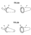
- Figure 12b shows another embodiment of a polarizer which is consists of an axial slot 19b formed at the open end of the female separable element 10 and a complementary projection 27b on the rear part of the male separable element 20. Obviously, we could use a reverse layout.
- a high voltage connector is thus produced. ensuring excellent electrical insulation continuity and avoiding all risk of air inclusion which could affect the continuity of insulation without the need to use oil or grease insulation.
Description
La présente invention concerne, d'une manière générale, un ensemble à haute tension comprenant des éléments séparables et plus particulièrement un tel ensemble à haute tension dans lequel la continuité d'isolation électrique entre les éléments séparables est assurée au moyen d'un élément en matériau isolant, élastiquement déformable. Voir comme exemple le document US-A-4 296 986.The present invention relates, in general, to a high voltage assembly comprising separable elements and more particularly such a high voltage assembly in which the continuity of electrical insulation between separable elements is ensured by an element of insulating material, elastically deformable. See, for example, document US-A-4,296,986.
Dans les systèmes à haute tension, par exemple 40 kV à 150 kV ou plus, comportant des éléments séparables, tels que les éléments de raccordement d'un câble à haute tension à un appareil sous haute tension, par exemple un générateur à haute tension ou la gaine d'un tube à rayons X, le raccordement électrique s'effectue classiquement au moyen de contacts électriques appariés maintenus dans des blocs isolants rigides, eux mêmes disposés dans des enveloppes métalliques permettant une réunion mécanique sûre des éléments de raccordement, par exemple au moyen de filetage et taraudage complémentaires sur les enveloppes ou d'un dispositif à baïonnette. Lors de ce raccordement des éléments séparables à haute tension, le contact mâle d'un des éléments s'adapte dans le contact femelle de l'autre élément et les deux éléments sont réunis sous une pression, de telle sorte que les faces transversales terminales des blocs isolants rigides, généralement planes, viennent s'appliquer l'une contre l'autre le plus - étroitement possible, sous l'action de la pression exercée par les enveloppes métalliques, pour réaliser une continuité d'isolation électrique entre les éléments séparables.In high voltage systems, for example 40 kV to 150 kV or plus, with separable elements, such as connection of a high voltage cable to a high voltage device voltage, for example a high-voltage generator or the sheath of a X-ray tube, electrical connection is made conventionally by means of paired electrical contacts held in blocks rigid insulation, themselves arranged in metal envelopes allowing a secure mechanical assembly of the connection elements, for example by means of additional threading and tapping on the envelopes or bayonet device. During this connection high voltage separable elements, the male contact of one of elements fits into the female contact of the other element and both elements are brought together under pressure, so that the faces transverse end of rigid insulating blocks, generally flat, press against each other most closely possible, under the action of the pressure exerted by the envelopes metallic, to achieve continuity of electrical insulation between separable elements.
Afin d'améliorer l'isolation électrique à l'interface entre les éléments séparables de tels ensembles à haute tension et ainsi éviter autant que possible l'apparition de décharges électriques entre les contacts et les enveloppes métalliques formant masse électrique à l'interface de raccordement des éléments séparables, on dispose généralement à cette interface de l'huile ou une graisse isolante. On évite ainsi la présence d'air à l'interface de raccordement entre les éléments, air qui a pour inconvénient d'interrompre la continuité de l'isolation électrique du fait d'un changement brutal de la constante diélectrique. L'utilisation d'huile ou de graisse pour améliorer la continuité d'isolation entre des éléments séparables d'un ensemble à haute tension, nécessite des constructions complexes des éléments pour assurer une étanchéité vis-à-vis de l'huile ou de la graisse de l'ensemble à haute tension. En effet, en fonctionnement, l'ensemble de raccordement à haute tension ainsi que l'huile ou la graisse se trouvent à une température relativement élevée, et les différences de dilatation thermique des divers composants des éléments ainsi que de l'huile ou de la graisse entraínent un risque potentiel de perte d'étanchéité de l'ensemble résultant en une fuite d'huile ou de graisse et par conséquent un abaissement du niveau d'isolation élecrique de l'ensemble de raccordement à haute tension. Ce problème d'étanchéité est particulièrement important lorsque l'ensemble à haute tension se . trouve dans un système tournant, par exemple les gaines de certains appareils de radiographie aux rayons X. Il est alors nécessaire de prévoir des moyens d'étanchéité complexes tels que des bagues à soufflet pour éviter une fuite d'huile ou de graisse au niveau de l'interface entre les éléments séparables, en particulier sous l'effet de la température lors de l'utilisation de l'ensemble afin de compenser la variation de volume.In order to improve the electrical insulation at the interface between the separable elements of such high voltage assemblies and thus avoid as much as possible the appearance of electric shocks between contacts and metallic enclosures forming electrical ground to the interface for separating separable elements, we have usually at this interface oil or insulating grease. We thus avoids the presence of air at the connection interface between the elements, air which has the disadvantage of interrupting the continuity of electrical insulation due to a sudden change in the constant dielectric. The use of oil or grease to improve the continuity of insulation between separable elements of a high voltage, requires complex construction of elements to ensure a seal against oil or grease the high voltage assembly. Indeed, in operation, all of high voltage connection as well as oil or grease are present at a relatively high temperature, and the differences in expansion thermal of the various components of the elements as well as oil or of grease leads to a potential risk of loss of sealing of the whole resulting in an oil or grease leak and by consequently a lowering of the electrical insulation level of the high voltage connection assembly. This sealing problem is particularly important when the high voltage assembly is. found in a rotating system, for example the sheaths of some x-ray x-ray equipment. It is then necessary to provide complex sealing means such as rings bellows to prevent oil or grease leaking from the interface between the separable elements, in particular under the effect of the temperature when using the set to compensate for the volume variation.
De plus, après utilisation, il est parfois difficile avec de tels ensembles de raccordement connus de séparer les éléments séparables de l'ensemble.In addition, after use, it is sometimes difficult with such known connection assemblies to separate separable elements from the whole.
La présente invention a donc pour objet de réaliser un ensemble à haute tension comportant des éléments séparables, dans lequel il n'est pas nécessaire d'utiliser de l'huile ou de la graisse pour assurer la continuité d'isolation électrique entre les éléments séparables de l'ensemble.The object of the present invention is therefore to produce an assembly with high voltage with separable elements, in which it is not no need to use oil or grease to ensure continuity of electrical insulation between the separable elements of all.
L'invention a encore pour but de fournir un ensemble à haute tension comprenant des éléments séparables qui peuvent être aisément assemblés lors de la fabrication ou l'installation et désassemblés après utilisation ou pour intervention.Another object of the invention is to provide a set with high tension comprising separable elements which can be easily assembled during manufacture or installation and disassembled after use or intervention.
Un ensemble à haute tension comprend au moins deux éléments séparables, chacun des éléments séparables comportant au moins un contact électrique ayant une face transversale terminale, lesdits contacts d'un élément séparable se raccordant électriquement audit contact de l'autre des éléments séparables lorsque les éléments séparables sont réunis, dans lequel la continuité de l'isolation électrique autour des contacts est réalisée au moyen d'un élément d'isolation en matériau électriquement isolant et élastiquement déformable, déformé par compression, lorsque les éléments séparables sont raccordés l'un à l'autre.A high voltage assembly includes at least two elements separable, each of the separable elements comprising at least one electrical contact having a terminal transverse face, said contacts of a separable element electrically connected to said contact of the other separable elements when the elements separable are joined together, in which the continuity of the insulation electrical around the contacts is achieved by means of an element of insulation made of electrically insulating and elastically insulating material deformable, deformed by compression, when the separable elements are connected to each other.
Un élément d'isolation déformable assurant la continuité de l'isolation électrique peut être un joint élastiquement déformable, en matériau isolant, disposé entre des faces transversales terminales de blocs rigides en matériau isolant de manière à entourer le (ou les) contact(s) électrique(s). Le joint est déformé par compression entre les faces transversales terminales des blocs rigides en matériau isolant, pour réaliser une continuité d'isolation électrique de l'ensemble à haute tension, lorsque les éléments séparables sont réunis.An insulation element deformable ensuring continuity of electrical insulation can be a joint elastically deformable, made of insulating material, arranged between faces transverse end of rigid blocks of insulating material so as to surround the electrical contact (s). The seal is deformed by compression between the terminal transverse faces of rigid blocks of insulating material, to achieve continuity electrical insulation of the high-voltage assembly, when the separable elements are combined.
Un joint élastiquement déformable peut être réalisé en tout matériau isolant souple, élastiquement déformable, ayant des caractéristiques d'isolation électrique appropriées et une dureté appropriée pour pouvoir être comprimé entre les blocs en matériau isolant des éléments séparables et suffisamment se déformer pour remplir parfaitement, à l'état comprimé, l'espace entre les blocs isolants rigides autour des contacts. En se déformant par compression, le joint isolant souple s'adapte parfaitement aux faces transversales terminales des blocs isolants rigides et ainsi remédie aux imperfections de surface éventuelles de ces faces transversales terminales.An elastically deformable joint can be produced in any flexible, elastically deformable insulating material having suitable electrical insulation characteristics and hardness suitable for being able to be compressed between the blocks of material insulating separable elements and deforming enough to perfectly fill, in compressed state, the space between the blocks rigid insulation around the contacts. By deforming by compression, the flexible insulating joint adapts perfectly to the transverse faces rigid insulating blocks and thus remedies possible surface imperfections of these transverse faces terminal.
De préférence, un joint souple, élastiquement déformable, est en un matériau élastomère approprié, tel qu'un élastomère de silicone.Preferably, a flexible, elastically deformable seal is in a suitable elastomeric material, such as a silicone elastomer.
La dureté Shore A du matériau isolant souple d'un joint est généralement comprise entre 10 et 50, de préférence entre 10 et 30.The Shore A hardness of the flexible insulating material of a joint is generally between 10 and 50, preferably between 10 and 30.
La pression exercée par les éléments séparables sur le joint isolant souple doit être suffisante pour réaliser l'isolation électrique voulue. Bien évidemment, cette pression sera fonction de la dureté (souplesse) et de la nature du matériau du joint et de la haute tension d'utilisation de l'ensemble.The pressure exerted by the separable elements on the insulating joint flexible must be sufficient to achieve the desired electrical insulation. Obviously, this pressure will depend on the hardness (flexibility) and the nature of the gasket material and the high operating voltage from the whole.
Un joint isolant souple peut être un joint amovible, c'est-à-dire qu'il constitue un élément distinct des éléments séparables. Toutefois, ce joint peut être également solidaire d'une face terminale transversale d'un bloc isolant rigide, par exemple, par fixation au moyen d'une colle appropriée à ladite face.A flexible insulating joint can be a removable joint, i.e. that it constitutes a separate element from the separable elements. However, this joint can also be integral with a transverse end face a rigid insulating block, for example, by fixing by means of a adhesive suitable for said face.
Les faces transversales terminales des blocs rigides en matériau isolant des éléments séparables ont une forme convexe où le joint souple a une forme biconvexe, de telle sorte que lors de la réunion des éléments séparables de l'ensemble, il se forme temporairement des espaces annulaires en forme de coin entre le joint souple et les faces transversales terminales des blocs isolants rigides des éléments, permettant à l'air de s'échapper de l'interface entre les deux éléments séparables, jusqu'à ce que ces espaces aient totalement disparu lorsque les deux éléments séparables ont atteint leur position définitive d'accouplement et que le joint souple comprimé sous l'effet de la pression exercée par les blocs rigides en matériau isolant occupe la totalité de l'espace entre les blocs en matériau isolant des deux éléments séparables. On réalise ainsi un ensemble à haute tension comportant des éléments séparables qui, lorsque ceux-ci sont réunis, a une excellente continuité d'isolation électrique.The transverse faces rigid blocks in insulating material separable have a convex shape where the flexible joint has a shape biconvex, so that when meeting elements separable from the whole, spaces are temporarily formed annular wedges between the flexible joint and the faces transverse end of the rigid insulating blocks of the elements, allowing air to escape from the interface between the two elements separable, until these spaces have completely disappeared when the two separable elements have reached their final position coupling and that the flexible seal compressed under the effect of the pressure exerted by rigid blocks of insulating material occupies the entire space between the blocks of insulating material of the two separable elements. This produces a high voltage assembly comprising separable elements which, when combined, have excellent continuity of electrical insulation.
La convexité des faces transversales terminales des blocs isolants ou du joint amovible souple doit être telle que les espaces en forme de coin créés lors de la réunion des éléments séparables soient seulement de quelques degrés pour permettre à l'air de s'échapper et ainsi éviter que de l'air ne soit piégé aux interfaces entre les éléments séparables et le joint, et pour assurer que le joint souple isolant ne laisse subsister aucun intervalle d'air lorsque les éléments séparables sont dans leur position de réunion finale. De préférence, la convexité est telle que l'angle des espaces en forme de coin est généralement compris entre 1 et 5°.The convexity of the terminal transverse faces of the insulating blocks or flexible removable joint should be such that the spaces in the form of corner created during the meeting separable elements are only a few degrees to allow air to escape and thus avoid air is trapped at the interfaces between the separable elements and the joint, and to ensure that the flexible insulating joint does not leave no air gaps remain when the separable elements are in their final meeting position. Preferably, the convexity is such that the angle of the wedge-shaped spaces is generally between 1 and 5 °.
Un connecteur haute tension selon un aspect l'invention comprend deux éléments séparables. Un premier des éléments séparables est constitué par une enveloppe creuse de forme tronconique, ouverte à une extrémité, en matériau isolant rigide, pourvue dans sa paroi de fond d'un ou plusieurs contacts électriques, par exemple des contacts femelles. Le second élément séparable comprend un bloc tronconique en matériau électriquement isolant, solide, déformable élastiquement par compression et dont la face avant est destinée à venir buter contre la paroi de fond de l'enveloppe tronconique et comporte un ou plusieurs contacts électriques, par exemple des contacts mâles, destinés à se raccorder avec le ou les contacts femelles du premier élément séparable. La hauteur du bloc isolant élastiquement déformable est légèrement supérieure, par exemple de 1 à 5 mm, à la profondeur du volume intérieur de l'enveloppe tronconique rigide creuse.A high voltage connector according to one aspect of the invention comprises two separable elements. A first of the separable elements is constituted by an envelope hollow frustoconical shape, open at one end, of material rigid insulation, provided in its bottom wall with one or more electrical contacts, for example female contacts. The second separable element includes a frustoconical block of material electrically insulating, solid, elastically deformable by compression and whose front face is intended to abut against the bottom wall of the frustoconical envelope and comprises one or more electrical contacts, for example male contacts, intended to be connect with the female contact (s) of the first element separable. The height of the insulating block elastically deformable is slightly higher, for example by 1 at 5 mm, at the depth of the interior volume of the envelope rigid tapered hollow.
Ainsi, lorsque le second élément séparable du connecteur haute tension est emboíté dans le premier élément séparable, puis comprimé, par exemple au moyen d'un écrou de serrage prévu sur le second élément séparable et coopérant avec un filetage complémentaire prévu sur le support dans lequel est adapté le premier élément séparable, le bloc isolant élastiquement déformable, se trouve déformé de telle sorte que le matériau élastiquement déformable remplisse totalement le volume intérieur de l'enveloppe tronconique creuse, entrant en contact étroit et sans discontinuité avec les parois internes de cette enveloppe. Un joint annulaire est disposé entre une bride annulaire du premier élément séparable et une bride annulaire du second élément separable.So when the second separable element of the high connector tension is fitted in the first separable element, then compressed, for example by means of a tightening nut provided on the second separable element and cooperating with a complementary thread provided on the support in which the first separable element is fitted, the elastically deformable insulating block, is deformed so that the elastically deformable material completely fills the internal volume of the hollow frustoconical envelope, coming into contact narrow and without discontinuity with the internal walls of this envelope. An annular seal is arranged between a flange ring of the first separable element and a flange annular of the second separable element.
Selon un aspect de l'invention, l'angle au sommet de l'enveloppe tronconique rigide du premier élément séparable est légèrement supérieur à l'angle au sommet du bloc d'isolation tronconique du second élément séparable, de sorte que, lorsque les deux éléments séparables sont simplement emboítés l'un dans l'autre, c'est-à-dire sans qu'une compression soit exercée sur le bloc d'isolation déformable du second élément séparable, il existe un petit espace annulaire angulaire, par exemple de 1 à 5°, entre la paroi latérale intérieure de l'enveloppe tronconique rigide et la paroi latérale externe du bloc tronconique en matériau isolant élastiquement déformable.According to one aspect of the invention, the angle at the top of the frustoconical envelope rigid of the first separable element is slightly greater than the angle at the top of the frustoconical insulation block of the second element separable, so that when the two separable elements are simply nested one inside the other, that is to say without a compression is exerted on the deformable insulation block of the second separable element, there is a small angular annular space, for example from 1 to 5 °, between the inner side wall of the envelope rigid frustoconical and the external side wall of the frustoconical block in elastically deformable insulating material.
Du fait de la présence initiale de l'espace annulaire angulaire entre la paroi interne de l'enveloppe tronconique creuse et de la paroi latérale externe du bloc en matériau isolant élastiquement déformable, l'air est chassé et évacué au fur et à mesure de la déformation par compression du bloc en matériau isolant élastiquement déformable jusqu'à ce que le bloc en matériau isolant élastiquement déformable remplisse totalement le volume intérieur de l'enveloppe tronconique lorsque l'écrou de serrage est vissé dans sa position finale. On assure ainsi une isolation électrique continue, sans risque de présence d'air inclus et sans qu'il soit nécessaire d'utiliser une huile ou une graisse isolante. Bien évidemment, lors de la séparation des éléments séparables, le bloc isolant élastiquement déformable retrouve ses forme et dimension initiales.Due to the initial presence of the angular annular space between the inner wall of the hollow frustoconical envelope and the wall external lateral of the block of elastically deformable insulating material, the air is expelled and evacuated as the deformation takes place compression of the block of elastically deformable insulating material until the block of elastically deformable insulating material completely fills the interior volume of the frustoconical envelope when the tightening nut is screwed into its final position. We assure thus continuous electrical insulation, without risk of air presence included and without the need to use oil or grease insulating. Obviously, when separating the elements separable, the elastically deformable insulating block regains its initial shape and size.
Comme indiqué précédemment, le bloc d'isolation du second élément séparable et/ou le joint annulaire sont de préférence constitués d'un élastomère approprié, tel qu'un élastomère de silicone. Ce matériau a généralement une dureté Shore A comprise entre 10 et 50, de préférence entre 10 et 30.As previously indicated, the insulation block of the second separable element and / or the annular seal preferably consist of an elastomer suitable, such as a silicone elastomer. This material has generally a Shore A hardness between 10 and 50, of preferably between 10 and 30.
La pression exercée sur le bloc en matériau isolant élastiquement déformable doit être telle qu'elle permette une réduction de la hauteur du bloc à la valeur de la profondeur du volume interne de l'enveloppe tronconique rigide. Bien évidemment, cette hauteur supplémentaire du bloc isolant en matériau élastiquement déformable doit être telle que le bloc, lorsqu'il est totalement déformé par compression, remplisse entièrement le volume intérieur de l'enveloppe tronconique creuse, rigide.The pressure exerted on the block of elastically insulating material deformable must be such as to allow a reduction in height of the block to the value of the depth of the internal volume of the envelope rigid frustoconical. Obviously, this additional height of the insulating block of elastically deformable material must be such that the block, when completely deformed by compression, fills the entire interior volume of the hollow frustoconical envelope, rigid.
Le ou les contacts électriques du second élément séparable sont généralement disposés dans des évidements ménagés dans la face avant du bloc en matériau isolant élastiquement déformable de manière à ce que ces contacts ne saillent pas à l'extérieur de cette face avant du bloc isolant. Bien évidemment, ces évidements sont conformés et dimensionnés pour recevoir les contacts électriques complémentaires du premier élément séparable. Ainsi, on évite tout risque de détérioration des contacts électriques du second élément séparable lors de la manipulation du connecteur. De préférence, les contacts électriques disposés dans les évidements du bloc isolant en matériau élastiquement déformable sont des contacts mâles, et de préférence encore des contacts mâles formant latéralement ressort de contact destinés à être introduits dans des contacts femelles complémentaires portés par la paroi de fond de l'enveloppe tronconique rigide creuse du premier élément séparable.The electrical contact (s) of the second separable element are generally arranged in recesses in the front face of the block of elastically deformable insulating material so that that these contacts do not project outside of this front face of the insulating block. Obviously, these recesses are shaped and sized to receive additional electrical contacts of the first separable element. This avoids any risk of deterioration of the electrical contacts of the second separable element during handling of the connector. Preferably, the contacts electrical devices arranged in the recesses of the insulating block of material elastically deformable are male contacts, and preferably still male contacts laterally forming contact spring intended to be inserted into complementary female contacts carried by the bottom wall of the hollow rigid frustoconical envelope of the first separable element.
Enfin, on peut prévoir sur l'extrémité ouverte de l'enveloppe rigide du premier élément séparable une partie plane et à l'arrière du second élément séparable une partie plane ou tout autre moyen de détrompage analogue, tel que des parties complémentaires positives ou négatives empêchant une rotation relative des éléments mâle et femelle, de telle sorte que les éléments séparables ne peuvent être raccordés que dans une seule position pour éviter toute détérioration éventuelle des contacts électriques lors dû raccordement. Bien évidemment, ces moyens de détrompage doivent, pour être efficaces, entrer en action avant tout engagement des contacts.Finally, one can provide on the open end of the envelope rigid of the first separable element a flat part and at the rear of the second separable element a flat part or any other means of similar coding, such as positive complementary parts or negative preventing relative rotation of the male elements and female, so that the separable elements cannot be connected in only one position to avoid any deterioration possible electrical contacts during connection. Well Obviously, these keying devices must, to be effective, take action before any engagement of contacts.
La suite de la description se réfère aux dessins annexés qui
représentent respectivement :
Pour une meilleure compréhension de l'invention telle
que revendiquée,
sur les figures 1 à 6, et en particulier sur les figures 1 et 2, on a
représenté schématiquement une réalisation d'un ensemble à haute
tension à titre indicatif, pour aider à la compréhension de l'invention. L'ensemble comprend deux éléments
séparables 1a, 1b, comportant chacun un contact électrique 2a, 2b,
maintenu fixement dans un bloc rigide en matériau isolant 3a, 3b, et
relié, comme cela est bien connu, à un conducteur électrique
d'alimentation ou différents organes devant fonctionner sous une haute
tension. Les éléments séparables de tels ensembles comprennent
classiquement des enveloppes métalliques complémentaires pourvues
de moyens coopérants appropriés permettant de réunir fixement entre
eux les éléments séparables de l'ensemble. Ces enveloppes métalliques
constituent une masse électrique schématiquement représentée par le
bloc 5 sur les figures 1 et 2.For a better understanding of the invention such
than claimed,
in FIGS. 1 to 6, and in particular in FIGS. 1 and 2, we have
schematically depicted an embodiment of a high set
tension as an indication, to help the understanding of the invention. The set includes two elements
separable 1a, 1b, each comprising an
Comme cela est bien connu, il existe un risque d'apparition d'arc
électrique entre les contacts réunis 2a et 2b et les enveloppes
métalliques constituant la masse électrique 5 au niveau de l'interface
entre les éléments.As is well known, there is a risk of arcing
electric between the joined
Comme le montrent les figures 1 et 2, l'ensemble à haute tension,
comprend en outre un joint amovible 6 en matériau
isolant souple, élastiquement déformable, de forme annulaire, disposé
entre les faces transversales terminales des blocs rigides en matériau
isolant des éléments de l'ensemble et entourant les contacts électriques
2a, 2b.As shown in FIGS. 1 and 2, the high voltage assembly,
further includes a
Comme le montre plus particulièrement la figure 2, lorsque les
éléments séparables de l'ensemble à haute tension sont réunis de façon
à accoupler les contacts électriques 2a et 2b des éléments, le joint en
matériau isolant souple 6 se déforme sous l'effet de la pression
qu'exercent les faces des blocs isolants rigides des éléments, de façon
à épouser étroitement la configuration de ces faces transversales
terminales 4a, 4b, réalisant ainsi une continuité d'isolation électrique
de l'ensemble lorsque les éléments séparables sont réunis.As shown more particularly in Figure 2, when the
separable elements of the high-voltage assembly are brought together so
to couple the
Comme le montrent plus particulièrement les figures 3 et 4, dans une réalisation recommandée, on prévoit un moyen d'évacuation de l'air aux interfaces entre les faces transversales terminales 4a et 4b des blocs d'isolation rigides des éléments séparables de l'ensemble à haute tension et le joint isolant souple.As shown more particularly in Figures 3 and 4, in a recommended implementation, a means of evacuation of the air at the interfaces between the terminal transverse faces 4a and 4b of the rigid insulation blocks of separable elements from the high assembly tension and flexible insulating joint.
Comme le montre la figure 3, ce moyen d'évacuation de l'air peut
être réalisé en conférant aux faces transversales terminales 4a et 4b
des blocs une convexité telle qu'il se forme un espace annulaire en
forme de coin entre les faces transversales terminales 4a, 4b des blocs
rigides et les surfaces transversales correspondantes du joint 6.
L'angle α ainsi obtenu est généralement de quelques degrés. Ainsi, la
convexité des faces transversales terminales 4a, 4b des blocs rigides
3a, 3b doit être telle qu'il se forme des espaces annulaires en forme de
coin, mais ne doit pas être si importante qu'il ne serait plus possible
de faire disparaítre ces espaces annulaires par compression du joint
souple 6 lors de la réunion des éléments séparables 1a, 1b. La valeur
de l'angle α dépendra aussi bien évidemment de la dureté du matériau
isolant du joint 6. En général, cet angle α sera compris entre 1 et 5°.As shown in Figure 3, this means of air evacuation can
be produced by conferring on the transverse end faces 4a and 4b
of the blocks a convexity such that an annular space is formed in
wedge shape between the terminal transverse faces 4a, 4b of the blocks
rigid and the corresponding transverse surfaces of the
Lorsque les éléments séparables sont réunis pour réaliser la
connexion électrique de ceux-ci, il se forme donc un espace annulaire
en forme de coin s'évasant vers la périphérie des blocs rigides 3a et 3b
des éléments séparables entre les surfaces transversales terminales
convexes 4a et 4b de ces blocs et les surfaces transversales du joint
amovible en matériau isolant élastiquement déformable de forme
annulaire, cet espace se réduisant pour finalement entièrement
disparaítre sous l'effet de la compression du joint amovible annulaire 6
lorsque les éléments séparables sont réunis dans leur position finale.
Ainsi, l'air est chassé des interfaces entre les faces terminales
transversales convexes 4a et 4b des blocs d'isolation rigides des
éléments séparables et le joint 6 et ne se trouve pas piégé entre les
faces transversales terminales des blocs rigides des éléments
séparables et les faces transversales du joint amovible, par exemple en
cas de défauts existants dans les faces transversales terminales des
blocs rigides isolants des éléments séparables. De ce fait, on réalise
une isolation électrique excellente entre les éléments séparables.When the separable elements are brought together to achieve the
electrical connection of these, so an annular space is formed
wedge-shaped widening towards the periphery of the
Comme le montre la figure 4, on peut également réaliser une
évacuation de l'air entre les éléments séparables 1a et 1b de l'ensemble
à haute tension, comportant des blocs isolants rigides dont les faces
transversales terminales sont planes, en réalisant un joint amovible en
matériau isolant élastiquement déformable, annulaire, biconvexe,
c'est-à-dire dont les faces transversales ont une légère convexité de
façon, comme précédemment, à réaliser temporairement des espaces en
forme de coin analogues à ceux décrits en liaison avec la figure 3, lors
de la réunion des éléments séparables de l'ensemble à haute tension.As shown in Figure 4, one can also perform a
air evacuation between
On a représenté, à la figure 5, un ensemble de connexion à haute tension entre un câble d'alimentation à haute tension et une prise d'un dispositif sous haute tension, telle que par exemple un générateur haute tension -où la gaine d'un tube à rayons X.In FIG. 5, a high voltage connection set between a cable high voltage power supply and a socket of a device under high voltage, such as for example a high voltage generator -where the sheath an X-ray tube.
Comme le montre la figure 5, l'ensemble à haute tension comporte
deux éléments de raccordement séparables 10a, 10b. L'élément
séparable 10a est relié fixement à l'enveloppe d'un dispositif à haute
tension, par exemple un générateur à haute tension, à l'aide d'une
enveloppe métallique de forme générale cylindrique, dont l'extrémité
située à l'extérieur du dispositif haute tension comporte un filetage.
Un contact électrique 12a, par exemple un contact mâle, est maintenu
à l'intérieur de l'enveloppe métallique cylindrique 15a au moyen d'un
bloc isolant rigide 13a. Comme cela est bien connu, les divers
éléments composant le dispositif sous haute tension sont
électriquement isolés au moyen d'un remplissage d'huile isolante.
L'élément de raccordement séparable 10b de l'ensemble de connexion
comprend une enveloppe métallique de forme généralement
cylindrique dont une extrémité est pourvue d'un taraudage destiné à
coopérer avec le filetage de l'enveloppe 15a de l'élément fixé au
dispositif à haute tension. L'autre extrémité de l'enveloppe 15b de
l'élément de raccordement 10b est fixée à l'extrémité d'un câble à
haute tension 17. Un contact électrique 12b, par exemple un contact
femelle, est maintenu à l'intérieur de l'enveloppe 15b au moyen d'un
bloc isolant rigide 13b. Comme cela est bien connu, ce contact 12b est
réuni au conducteur du câble à haute tension. Comme cela est
également bien connu lors de la réunion des éléments séparables de
l'ensemble de connexion, les contacts 12a et 12b s'accouplent pour
réaliser la continuité électrique entre les deux éléments de l'ensemble
de connexion.As shown in Figure 5, the high voltage assembly includes
two separable connecting
Comme le montre encore la figure 5, un joint annulaire en
matériau isolant souple, élastiquement déformable, est disposé entre
les faces transversales terminales 14a et 14b des blocs isolants rigides
13a et 13b. Comme indiqué précédemment, lors de la réunion des deux
éléments séparables au moyen des enveloppes métalliques 15a et 15b
par vissage, respectivement, de leur extrémité taraudée et filetée, le
joint annulaire en matériau isolant souple est comprimé entre les faces
transversales 14a et 14b des blocs isolants 13a et 13b jusqu'à ce que
les contacts 12a et 12b soient réunis. Le joint amovible souple
annulaire 16 comprimé entre les faces transversales 14a et 14b des
blocs 13a et 13b, assure ainsi une continuité d'isolation excellente
entre les éléments séparables 10a, 10b. Ainsi, il est possible d'obtenir
une isolation électrique entre des éléments séparables selon l'invention
pour des tensions allant jusqu'à 160 kV et plus. D'autre part, comme
cela est bien connu, dans les ensembles séparables connus, il pouvait
être difficile, après utilisation de ceux-ci, de séparer à nouveau les
éléments. En utilisant un joint amovible en matériau isolant
élastiquement déformable les éléments séparables de
l'ensemble à haute tension sont aisément séparables même après
utilisation.As still shown in FIG. 5, an annular seal in
flexible, elastically deformable insulating material is disposed between
the transverse end faces 14a and 14b of the rigid insulating
Bien que l'on ait décrit des éléments séparables comportant chacun un contact électrique, il est bien évident que chacun des éléments peut comporter deux contacts ou plus maintenus dans les blocs isolants rigides. Dans ce cas, bien évidemment, le joint amovible en matériau isolant élastiquement déformable comportera le nombre nécessaire de passages pour permettre la réunion des contacts coopérants de ces éléments séparables.Although separable elements have been described comprising each an electrical contact, it is obvious that each of the elements may have two or more contacts held in the rigid insulating blocks. In this case, of course, the removable seal of elastically deformable insulating material will include the number necessary passages to allow the meeting of contacts cooperating with these separable elements.
La figure 6 représente schématiquement un ensemble modulaire à haute tension.FIG. 6 schematically represents a modular assembly with high tension.
A titre d'exemple, l'ensemble modulaire peut comporter un
premier module 10, par exemple les enroulements secondaires d'un
générateur à haute tension contenus dans une enveloppe en matière
plastique rigide, un second module 20 constitué par un bloc de
redressement et de filtrage, également contenu dans une enveloppe en
matière plastique rigide, un troisième module 30 constituant un bloc
de connexion de sortie, et des raccords 40a, 40b de câble à haute
tension.For example, the modular assembly may include a
Comme le montre la figure 6, les différents modules 10, 20, 30,
40a et 40b, sont électriquement reliables entre eux par des contacts
complémentaires. On prévoit entre chaque module
des joints amovibles en matériau isolant élastiquement déformable 11,
21, 31a et 31b, qui, lorsque les modules sont réunis entre eux, de
manière à réaliser la connexion électrique entre les différents modules,
sont comprimés cntre les modules adjacents, pour réaliser une
continuité d'isolation électrique entre les différents modules comme
cela a été décrit précédemment. On réalise ainsi un ensemble
modulaire à haute tension parfaitement isolé, simple, facile à monter
et démonter, et qui ne nécessite pas d'utiliser de l'huile ou de la
graisse entre les différents modules pour assurer l'isolation électrique.As shown in Figure 6, the
Bien évidemment, on peut conférer aux surfaces transversales des enveloppes des modules une légère convexité ou encore utiliser des joints isolants souples biconvexes pour, comme précédemment, réaliser une évacuation de l'air aux interfaces entre les modules et les joints. Obviously, we can give the transverse surfaces module envelopes a slight convexity or alternatively use biconvex flexible insulating joints for, as before, perform air evacuation at the interfaces between the modules and the joints.
On a représenté aux figures 7 à 12 une réalisation d'un connecteur haute tension, selon l'invention.Figures 7 to 12 show an embodiment a high voltage connector according to the invention.
En se référant aux figures 7 à 9, le connecteur haute tension
recommandé selon l'invention comprend deux éléments de connexion
séparables, un élément femelle 10 et un élément mâle 20.Referring to Figures 7 to 9, the high voltage connector
recommended according to the invention comprises two connection elements
separable, a
L'élément femelle 10 est destiné à être fixé à un appareil
fonctionnant sous haute tension, par exemple un générateur haute
tension ou la gaine d'un tube à rayons X, en vue de son alimentation
sous haute tension.The
Comme le montre la figure 7, cet élément séparable femelle 10 se
compose essentiellement d'une enveloppe tronconique, creuse, rigide,
en matériau électriquement isolant 11, par exemple une matière
plastique rigide. Cette enveloppe tronconique creuse comprend une
paroi de fond 12 et une paroi latérale 13, ouverte à son extrémité 15
opposée à la paroi de fond 12 et délimitant un volume intérieur 14.
Cette enveloppe tronconique est munie sur le pourtour de son
extrémité ouverte 15 d'une bride annulaire 16 pour son raccordement à
une paroi 30, mise à la masse électrique, de l'enveloppe métallique
d'un appareil haute tension. Cette paroi 30 de l'enveloppe de l'appareil
haute tension est également pourvue d'un moyen, par exemple un
filetage 31 destiné à coopérer avec un écrou de fixation 26 de
l'élément mâle de raccordement 20 du connecteur pour assurer une
connexion sûre des éléments séparables du connecteur.As shown in FIG. 7, this separable
Plusieurs, par exemple trois, contacts électriques femelles 17 sont
. disposés dans la paroi de fond 12 de l'enveloppe rigide creuse 11 et
font saillies dans le volume intérieur 14 de l'enveloppe. Ces contacts
électriques 17 sont d'autre part raccordés par des conducteurs 18 à des
organes appropriés de l'appareil haute tension.Several, for example three, female
Comme le montre le schéma de la figure 10, la paroi latérale 13 de
l'enveloppe tronconique rigide 11, s'évase depuis la paroi de fond 12
jusqu'à son extrémité ouverte 15 suivant un angle α déterminé par
rapport à l'axe longitudinal de l'enveloppe.As shown in the diagram in Figure 10, the
L'élément de connexion mâle 20 se compose d'un bloc tronconique
21 en matériau électriquement isolant, élastiquement déformable,
enrobant des conducteurs 22 reliés à un câble d'alimentation haute
tension 25 et se terminant à la face avant du bloc d'isolation 21 par
des contacts électriques mâles 23 destinés à se raccorder par enfichage
avec les contacts électriques femelles 17 de l'enveloppe tronconique
rigide 11. L'élément mâle 20 comporte également un écrou de serrage
26 comportant un taraudage coopérant avec le filetage 31 de
l'enveloppe de l'appareil pour réaliser une connexion fixe et sûre entre
les éléments séparables du connecteur. Bien qu'on ait représenté un
agencement à filetage et écrou solidarisé par vissage, on peut
également utiliser tout autre agencement bien connu de fixation des
éléments de connecteur, par exemple un agencement à baïonnette. La
partie de raccordement du câble haute tension au bloc isolant 21 est
constituée d'un matériau rigide, par exemple du métal.The
Le bloc tronconique 21 peut être constitué en totalité par le
matériau électriquement isolant, élastiquement déformable, ou peut
comporter une âme en matériau électriquement isolant rigide entourée
par le matériau électriquement isolant, élastiquement déformable.The frusto-
Comme le montre la figure 10, la paroi latérale externe du bloc
isolant 21 s'évase depuis sa face avant jusqu'à une bride annulaire de
support 28 assurant la liaison entre le bloc isolant 21 et le câble à
haute tension 25, suivant un angle β par rapport à l'axe longitudinal de
l'élément séparable mâle 20.As shown in Figure 10, the outer side wall of the
Comme le montrent clairement les figures 8 et 10, cet angle β est
plus petit de quelques degrés, par exemple 1 à 5°, que l'angle α de
l'enveloppe creuse 11 de l'élément séparable femelle 10, de telle sorte
- que lorsque l'élément séparable mâle 20 est simplement enboíté dans
l'élément séparable femelle 10 avec les contacts mâle 23 et femelle 17
raccordés, la surface externe de la paroi latérale du bloc isolant 21 de
l'élément mâle 20 définit avec la surface interne de la paroi latérale 13
de l'enveloppe creuse, rigide 11 de l'élément femelle 10, un espace
annulaire angulaire ou en forme de coin 40 qui s'évase en direction de
l'extrémité ouverte 15 de l'enveloppe rigide creuse 11.As clearly shown in Figures 8 and 10, this angle β is
smaller by a few degrees, for example 1 to 5 °, than the angle α of
the
En d'autres termes, l'angle au sommet de la paroi latérale 13 de
l'enveloppe rigide creuse 11 est supérieur à l'angle au sommet de la
paroi latérale du bloc d'isolation tronconique 21.In other words, the angle at the top of the
Selon un aspect de l'invention on prévoit un joint annulaire 41
en matériau isolant souple, par exemple en élastomère de silicone
entre la bride annulaire 28 de fixation de l'élément mâle 20 et la bride
annulaire 16 de l'enveloppe creuse, rigide 11 de l'élément femelle 10.According to one aspect of the invention, an
Comme le montre également la figure 5, dans la position
précédente, c'est-à-dire avant le vissage complet de l'écrou de fixation
26 de l'élément mâle 20 sur le filetage 31 de l'enveloppe de l'appareil,
le bloc isolant 21 saille extérieurement de l'enveloppe creuse rigide 11
d'une faible hauteur Δℓ, par exemple quelques millimètres, de
préférence 1 à 5 mm. En d'autres termes, la hauteur du bloc isolant 21
est supérieure d'une valeur Δℓ à la profondeur du volume intérieur 14
de l'enveloppe creuse rigide 11.As also shown in Figure 5, in the position
previous, i.e. before fully tightening the fixing
Comme le montre la figure 9, lorsque l'écrou de fixation 26 est
vissé à fond, il exerce une force de compression déterminée sur la
bride annulaire 28 et comprime le bloc isolant 21. Comme le bloc
isolant 21 est constitué d'un matériau isolant élastiquement
déformable, lors de la compression, il se déforme pour, lorsque l'écrou
de fixation 28 est totalement vissé, remplir entièrement le volume
intérieur 14 de l'enveloppe creuse rigide 11. Du fait de l'espace
annulaire angulaire 40 existant initialement entre le bloc isolant 21 et
la surface interne de la paroi latérale 13 de l'enveloppe creuse rigide
11, l'air est progressivement expulsé vers l'extérieur au fur et à mesure
que le bloc isolant se déforme pour occuper en totalité le volume
intérieur 14 de l'enveloppe creuse rigide 11. Ainsi, lorsque les
éléments séparables mâle 20 et femelle 10 du connecteur sont
- assemblés dans leur position finale, le bloc isolant 21 assure une
continuité de l'isolation électrique et évite tout risque d'inclusion
d'air, sans qu'il soit nécessaire d'utiliser une huile ou une graisse
isolante.As shown in Figure 9, when the fixing
Bien évidemment, la valeur de Δℓ dépendra du volume intérieur
14 de l'enveloppe creuse rigide 11 et des propriétés élastiques du
matériau utilisé pour former le bloc isolant 21.Obviously, the value of Δℓ will depend on the
Le bloc isolant 21 peut être simplement réalisé par moulage d'un
matériau synthétique élastiquement déformable et électriquement
isolant, par exemple un élastomère de silicone, sur les conducteurs et
autour des contacts électriques. The insulating
Comme on le voit sur les figures 7 et 11, les contacts électriques
mâles 23 sont logés dans des évidements 24 ménagés dans l'extrémité
avant du bloc isolant 21. Les évidements 24 sont conformés et
dimensionnés de manière à contenir entièrement les contacts mâles 23
et pour recevoir les contacts femelles 17 de l'élément séparable
femelle 10. Ainsi, les contacts électriques de l'élément séparable mâle
20 qui est généralement raccordé au câble haute tension, se trouvent
protégés de tout risque de détérioration lorsque l'élément séparable
mâle 20 n'est pas raccordé à l'élément séparable femelle 10 ou lors des
diverses manipulations. Bien évidemment, les contacts électriques
pourraient être inversés, l'élément séparable mâle comprenant des
contacts femelles et l'élément séparable femelle comportant des
contacts mâles.As seen in Figures 7 and 11, the
Comme représenté, on peut prévoir un évidement 24 distinct pour
chacun des contacts mâles 23, mais on pourrait tout aussi bien prévoir
un évidement unique dans lequel seraient logés tous les contacts.As shown, a
On a représenté figure 11 un type recommandé de contacts mâles
23. Les contacts mâles recommandés 23 assurent un emboítement à
ressort dans les contacts femelles 17 au moyen de lames conductrices
formant ressort 23 disposées, comme cela est bien connu, à la surface
latérale du contact.FIG. 11 shows a recommended type of
Enfin, comme le montre la figure 12a, et comme cela est bien
connu dans la technique, on peut prévoir à l'extrémité ouverte de
l'enveloppe creuse rigide 11 de l'élément séparable femelle 10 une
partie plate 19a et une partie plate correspondante 27a sur la partie
arrière de l'élément séparable mâle 20, de telle sorte que l'élément
séparable mâle 20 ne peut être introduit dans l'élément séparable
femelle 10 que dans une seule position, assurant ainsi un raccordement
sans risque de détérioration des contacts électriques.Finally, as shown in Figure 12a, and as is well
known in the art, one can provide at the open end of
the rigid
La figure 12b montre une autre réalisation d'un détrompeur qui se
compose d'une fente axiale 19b ménagée à l'extrémité ouverte de
l'élément séparable femelle 10 et d'une saillie complémentaire 27b sur
la partie arrière de l'élément séparable mâle 20. Bien évidemment, on
pourrait utiliser une disposition inverse.Figure 12b shows another embodiment of a polarizer which is
consists of an
On réalise ainsi, selon l'invention, un connecteur haute tension assurant une continuité d'isolation électrique excellente et évitant tout risque d'inclusion d'air risquant de nuire à la continuité d'isolation sans qu'il soit nécessaire d'utiliser de l'huile ou de la graisse d'isolation.According to the invention, a high voltage connector is thus produced. ensuring excellent electrical insulation continuity and avoiding all risk of air inclusion which could affect the continuity of insulation without the need to use oil or grease insulation.
Claims (7)
- High voltage connector, comprising:a first separable element (10) consisting of a hollow tapered casing (11) made from an electrically insulating and rigid material having a bottom wall (12) and a tapered side wall (13) defining an interior volume (14), and at least one first electrical contact (17) carried by the bottom wall (12) and projecting inside the casing;a second separable element (20) intended to engage in the first separable element (10) comprising a tapered insulation block (21) made of an electrically insulating and elastically deformable material having a front face intended to come into abutment on the bottom wall (12) of the first separable element (10) and in which is disposed at least one second electrical contact (23) complementary to the first and a side wall; anda means (26, 31) for fixing the first separable element (10) to the second separable element (20); the height of the tapered insulation block (21) of the second separable element being greater than the depth of the hollow rigid casing (11) of the first separable element (10), so that, when the tapered insulation block (21) is compressed by the fixing means (26, 31), it deforms and completely fills the interior volume (14) of the hollow rigid casing (11) of the first separable element (10), thereby ensuring the continuity of electrical insulation of the connector, characterized in that it comprises an annular seal (41) between an annular flange (28) of the first separable element (10) and an annular flange (16) of the second separable element (20).
- High voltage connector according to Claim 1, characterized in that the angle at the top of the side wall (13) of the hollow rigid tapered casing (11) is greater than the angle at the top of the side wall of the tapered insulation block (21) defining therebetween, before compression of the tapered insulation block (21), an angular annular space (40), allowing the evacuation of air during compression of the tapered insulation block (21).
- Connector according to Claim 1 or 2, characterized in that the second electrical contact(s) (23) is (are) disposed in a (several) recess(es) (24) made in the front face of the tapered insulation block (21).
- Connector according to any one of Claims 1 to 3, characterized in that the first electrical contact(s) is (are) a (several) female contact(s) and the second electrical contact(s) is (are) a (several) sprung male contact(s).
- Connector according to any one of Claims 1 to 4, characterized in that the tapered insulation block (21) consists of a silicone elastomer.
- Connector according to Claim 5, characterized in that the tapered insulation block (21) has a Shore A hardness of between 10 and 50, preferably between 10 and 30.
- Connector according to any one of the preceding claims, characterized in that the annular seal (41) consists of a silicone elastomer.
Applications Claiming Priority (3)
| Application Number | Priority Date | Filing Date | Title |
|---|---|---|---|
| FR9613897A FR2755797B1 (en) | 1996-11-14 | 1996-11-14 | HIGH-VOLTAGE ASSEMBLY WITH SEPARABLE ELEMENTS |
| FR9613897 | 1996-11-14 | ||
| PCT/FR1997/001961 WO1998021786A1 (en) | 1996-11-14 | 1997-11-03 | High voltage assembly with separable elements |
Publications (2)
| Publication Number | Publication Date |
|---|---|
| EP0938759A1 EP0938759A1 (en) | 1999-09-01 |
| EP0938759B1 true EP0938759B1 (en) | 2003-07-23 |
Family
ID=9497624
Family Applications (1)
| Application Number | Title | Priority Date | Filing Date |
|---|---|---|---|
| EP97913234A Expired - Lifetime EP0938759B1 (en) | 1996-11-14 | 1997-11-03 | High voltage assembly with separable elements |
Country Status (5)
| Country | Link |
|---|---|
| EP (1) | EP0938759B1 (en) |
| JP (1) | JP2001503564A (en) |
| DE (1) | DE69723720T2 (en) |
| FR (1) | FR2755797B1 (en) |
| WO (1) | WO1998021786A1 (en) |
Cited By (1)
| Publication number | Priority date | Publication date | Assignee | Title |
|---|---|---|---|---|
| EP2490302A1 (en) | 2011-02-15 | 2012-08-22 | GE Sensing & Inspection Technologies GmbH | High voltage plug connection part for high voltage cable and method for producing same |
Families Citing this family (6)
| Publication number | Priority date | Publication date | Assignee | Title |
|---|---|---|---|---|
| AU3674200A (en) * | 1999-04-13 | 2000-11-14 | Central Japan Railway Company | Linear cable connection |
| FR2817667B1 (en) * | 2000-12-01 | 2003-01-10 | Ge Med Sys Global Tech Co Llc | HIGH VOLTAGE ELECTRICAL CONNECTION DEVICE |
| CN100459304C (en) * | 2003-01-07 | 2009-02-04 | 皇家飞利浦电子股份有限公司 | High-voltage connector |
| US7601014B2 (en) | 2004-04-29 | 2009-10-13 | Koninklijke Philips Electronics N.V. | High-voltage rubber cone plug-in connector |
| CN106486257B (en) | 2014-06-23 | 2018-05-04 | 上海联影医疗科技有限公司 | high pressure generator |
| US11862900B2 (en) | 2021-10-01 | 2024-01-02 | Teledyne Defense Electronics, Llc | Low partial discharge high voltage connector and methods |
Family Cites Families (4)
| Publication number | Priority date | Publication date | Assignee | Title |
|---|---|---|---|---|
| DE2733123C3 (en) * | 1977-07-22 | 1982-03-11 | Rich. Seifert & Co Gmbh & Co Kg, 2070 Ahrensburg | X-ray tube |
| US4296986A (en) * | 1979-06-18 | 1981-10-27 | Amp Incorporated | High voltage hermetically sealed connector |
| GB8529454D0 (en) * | 1985-11-29 | 1986-01-08 | Raychem Gmbh | Cable connection |
| FR2719420A1 (en) * | 1994-04-29 | 1995-11-03 | Ge Medical Syst Sa | Electrical connector for high voltage cable |
-
1996
- 1996-11-14 FR FR9613897A patent/FR2755797B1/en not_active Expired - Fee Related
-
1997
- 1997-11-03 WO PCT/FR1997/001961 patent/WO1998021786A1/en active IP Right Grant
- 1997-11-03 JP JP52222698A patent/JP2001503564A/en not_active Ceased
- 1997-11-03 DE DE69723720T patent/DE69723720T2/en not_active Expired - Lifetime
- 1997-11-03 EP EP97913234A patent/EP0938759B1/en not_active Expired - Lifetime
Cited By (1)
| Publication number | Priority date | Publication date | Assignee | Title |
|---|---|---|---|---|
| EP2490302A1 (en) | 2011-02-15 | 2012-08-22 | GE Sensing & Inspection Technologies GmbH | High voltage plug connection part for high voltage cable and method for producing same |
Also Published As
| Publication number | Publication date |
|---|---|
| DE69723720D1 (en) | 2003-08-28 |
| FR2755797B1 (en) | 1998-12-31 |
| EP0938759A1 (en) | 1999-09-01 |
| FR2755797A1 (en) | 1998-05-15 |
| JP2001503564A (en) | 2001-03-13 |
| WO1998021786A1 (en) | 1998-05-22 |
| DE69723720T2 (en) | 2004-04-15 |
Similar Documents
| Publication | Publication Date | Title |
|---|---|---|
| FR2769756A1 (en) | BELLOWS RING FOR HIGH VOLTAGE CONNECTOR AND HIGH VOLTAGE CONNECTOR OBTAINED | |
| FR2953071A1 (en) | ELECTRICAL CONNECTOR HOUSING | |
| FR2554642A1 (en) | ELECTRICAL CONNECTOR | |
| EP0938759B1 (en) | High voltage assembly with separable elements | |
| FR2926920A1 (en) | ELECTRICITY INSULATING DISK FOR SUPPORTING A LINEAR CONDUCTOR AND ELECTRICAL ASSEMBLY COMPRISING THE DISK. | |
| EP1251617B1 (en) | Cable sealing | |
| EP0580469B1 (en) | Plug connection set and seating especially for avionics | |
| EP1111748A1 (en) | Interconnection system between medium or high voltage switchgear cubicles | |
| FR2713408A1 (en) | Electrical connector. | |
| EP3561978B1 (en) | Insulator for a cable end | |
| EP1577994B1 (en) | Electrical connection between high voltage switchgear cells | |
| EP0534846B1 (en) | Electrical connecting system for flat cable | |
| FR2467492A1 (en) | ELECTRICAL CONNECTOR WITH PERIPHERAL HERMETICITY SEAL | |
| EP0558407B1 (en) | Electrical connector provided with electrical connection between the respective contact parts | |
| EP0525583B1 (en) | High or very high voltage cable junction assembly | |
| FR2736461A1 (en) | Sealed insulated bushing for gas-filled electrical equipment - has conic female insert of insulating material accepting an insulated conic male part with a conductor passing through its centre | |
| FR2763430A1 (en) | Electrical connection block for rigid cables | |
| FR2621181A1 (en) | WATERPROOF ELECTRICAL CONNECTOR FOR USE IN LIQUID MEDIA | |
| FR2537791A1 (en) | Branch-off device for electrical cables | |
| EP4147316A1 (en) | Device for joining, and discharging the leakage currents from, two shroud portions for containing a pressurised gas | |
| EP2272135B1 (en) | Device for preventing the establishment of an electric arc between two conductive elements | |
| CA1296400C (en) | Electrical cable with impregnated paper sheathing and end connector | |
| FR2813452A1 (en) | SEALED PARTITIONING PARTITION AND THREE - PHASE SHIELDED ELECTRICAL INSTALLATION WITH GAS INSULATION PROVIDED WITH SUCH A PARTITION | |
| EP1274108A1 (en) | Gas blast circuit breaker pole which can be assembled or disassembled without appreciable gas losses | |
| FR2610459A1 (en) | ELECTRICAL CABLE, IN PARTICULAR ISOLATED TO IMPREGNATED PAPER, AT THE END OF WHICH A CONNECTING DEVICE IS REFLECTED |
Legal Events
| Date | Code | Title | Description |
|---|---|---|---|
| PUAI | Public reference made under article 153(3) epc to a published international application that has entered the european phase |
Free format text: ORIGINAL CODE: 0009012 |
|
| 17P | Request for examination filed |
Effective date: 19990614 |
|
| AK | Designated contracting states |
Kind code of ref document: A1 Designated state(s): DE |
|
| 17Q | First examination report despatched |
Effective date: 19990929 |
|
| GRAH | Despatch of communication of intention to grant a patent |
Free format text: ORIGINAL CODE: EPIDOS IGRA |
|
| GRAH | Despatch of communication of intention to grant a patent |
Free format text: ORIGINAL CODE: EPIDOS IGRA |
|
| GRAA | (expected) grant |
Free format text: ORIGINAL CODE: 0009210 |
|
| AK | Designated contracting states |
Designated state(s): DE |
|
| REF | Corresponds to: |
Ref document number: 69723720 Country of ref document: DE Date of ref document: 20030828 Kind code of ref document: P |
|
| PLBE | No opposition filed within time limit |
Free format text: ORIGINAL CODE: 0009261 |
|
| STAA | Information on the status of an ep patent application or granted ep patent |
Free format text: STATUS: NO OPPOSITION FILED WITHIN TIME LIMIT |
|
| 26N | No opposition filed |
Effective date: 20040426 |
|
| PGFP | Annual fee paid to national office [announced via postgrant information from national office to epo] |
Ref country code: DE Payment date: 20121128 Year of fee payment: 16 |
|
| REG | Reference to a national code |
Ref country code: DE Ref legal event code: R119 Ref document number: 69723720 Country of ref document: DE |
|
| PG25 | Lapsed in a contracting state [announced via postgrant information from national office to epo] |
Ref country code: DE Free format text: LAPSE BECAUSE OF NON-PAYMENT OF DUE FEES Effective date: 20140603 |
|
| REG | Reference to a national code |
Ref country code: DE Ref legal event code: R119 Ref document number: 69723720 Country of ref document: DE Effective date: 20140603 |