EP0938428B1 - Epizycloidale einwickelmaschine für paletten - Google Patents
Epizycloidale einwickelmaschine für paletten Download PDFInfo
- Publication number
- EP0938428B1 EP0938428B1 EP97935515A EP97935515A EP0938428B1 EP 0938428 B1 EP0938428 B1 EP 0938428B1 EP 97935515 A EP97935515 A EP 97935515A EP 97935515 A EP97935515 A EP 97935515A EP 0938428 B1 EP0938428 B1 EP 0938428B1
- Authority
- EP
- European Patent Office
- Prior art keywords
- rollers
- film
- pallets
- wrapping machine
- annular structure
- Prior art date
- Legal status (The legal status is an assumption and is not a legal conclusion. Google has not performed a legal analysis and makes no representation as to the accuracy of the status listed.)
- Expired - Lifetime
Links
- 239000000463 material Substances 0.000 claims abstract description 11
- 241000239290 Araneae Species 0.000 claims abstract description 5
- 239000004033 plastic Substances 0.000 claims abstract description 5
- 229920003023 plastic Polymers 0.000 claims abstract description 5
- 230000005540 biological transmission Effects 0.000 claims description 7
- 238000009987 spinning Methods 0.000 claims 1
- 230000001360 synchronised effect Effects 0.000 claims 1
- 230000008901 benefit Effects 0.000 description 6
- 238000004806 packaging method and process Methods 0.000 description 6
- 238000004804 winding Methods 0.000 description 6
- 230000009471 action Effects 0.000 description 5
- 230000001105 regulatory effect Effects 0.000 description 5
- 230000001788 irregular Effects 0.000 description 3
- 238000012423 maintenance Methods 0.000 description 3
- 238000004519 manufacturing process Methods 0.000 description 3
- 230000007246 mechanism Effects 0.000 description 3
- 230000036961 partial effect Effects 0.000 description 3
- 230000002093 peripheral effect Effects 0.000 description 3
- 230000009467 reduction Effects 0.000 description 3
- 230000000284 resting effect Effects 0.000 description 3
- 238000009825 accumulation Methods 0.000 description 2
- 230000008602 contraction Effects 0.000 description 2
- 230000001934 delay Effects 0.000 description 2
- 230000000694 effects Effects 0.000 description 2
- 230000008030 elimination Effects 0.000 description 2
- 238000003379 elimination reaction Methods 0.000 description 2
- 238000005304 joining Methods 0.000 description 2
- 239000002985 plastic film Substances 0.000 description 2
- 229920006255 plastic film Polymers 0.000 description 2
- 230000002829 reductive effect Effects 0.000 description 2
- 230000004044 response Effects 0.000 description 2
- 238000012546 transfer Methods 0.000 description 2
- 238000013519 translation Methods 0.000 description 2
- 239000004698 Polyethylene Substances 0.000 description 1
- 230000001133 acceleration Effects 0.000 description 1
- 230000003213 activating effect Effects 0.000 description 1
- 230000001070 adhesive effect Effects 0.000 description 1
- 230000002411 adverse Effects 0.000 description 1
- 238000004458 analytical method Methods 0.000 description 1
- 239000011449 brick Substances 0.000 description 1
- 238000006243 chemical reaction Methods 0.000 description 1
- 230000008878 coupling Effects 0.000 description 1
- 238000010168 coupling process Methods 0.000 description 1
- 238000005859 coupling reaction Methods 0.000 description 1
- 238000013461 design Methods 0.000 description 1
- 238000009434 installation Methods 0.000 description 1
- 230000000670 limiting effect Effects 0.000 description 1
- 230000014759 maintenance of location Effects 0.000 description 1
- 238000000034 method Methods 0.000 description 1
- -1 polyethylene Polymers 0.000 description 1
- 229920000573 polyethylene Polymers 0.000 description 1
- 230000002265 prevention Effects 0.000 description 1
- 230000001681 protective effect Effects 0.000 description 1
- 230000006641 stabilisation Effects 0.000 description 1
- 238000011105 stabilization Methods 0.000 description 1
- 238000003860 storage Methods 0.000 description 1
- 238000011144 upstream manufacturing Methods 0.000 description 1
- 238000005303 weighing Methods 0.000 description 1
Images

Classifications
-
- B—PERFORMING OPERATIONS; TRANSPORTING
- B65—CONVEYING; PACKING; STORING; HANDLING THIN OR FILAMENTARY MATERIAL
- B65B—MACHINES, APPARATUS OR DEVICES FOR, OR METHODS OF, PACKAGING ARTICLES OR MATERIALS; UNPACKING
- B65B11/00—Wrapping, e.g. partially or wholly enclosing, articles or quantities of material, in strips, sheets or blanks, of flexible material
- B65B11/02—Wrapping articles or quantities of material, without changing their position during the wrapping operation, e.g. in moulds with hinged folders
- B65B11/025—Wrapping articles or quantities of material, without changing their position during the wrapping operation, e.g. in moulds with hinged folders by webs revolving around stationary articles
-
- B—PERFORMING OPERATIONS; TRANSPORTING
- B65—CONVEYING; PACKING; STORING; HANDLING THIN OR FILAMENTARY MATERIAL
- B65B—MACHINES, APPARATUS OR DEVICES FOR, OR METHODS OF, PACKAGING ARTICLES OR MATERIALS; UNPACKING
- B65B2210/00—Specific aspects of the packaging machine
- B65B2210/14—Details of wrapping machines with web dispensers for application of a continuous web in layers onto the articles
- B65B2210/18—Details of wrapping machines with web dispensers for application of a continuous web in layers onto the articles the web dispenser being mounted on a rotary ring
Definitions
- the present invention relates to a wrapping machine for pallets.
- a wrapping machine for pallets in which the product to be wrapped is in a fixed position and packaging is performed by means of spiral winding of an extendable film onto the product.
- the tension of the film is approximately constant for an elongation variable from about 80% to about 300% and therefore it is preferred to stretch the film prior to winding thereof around the product, not only to provide it with the desired technical retaining characteristics, but also so as to use less material while achieving the same results.
- This elongation also referred to as pre-stretching, is generally performed at the same time as unwinding of the film, by causing the latter to pass between a pair of rubberized rollers, shortly spaced apart and having different rotational speeds: the downstream roller rotates faster than the upstream roller, causing elongation of the film.
- the short distance between the two rollers has the purpose of preventing transverse contraction of the extendable film, a contraction which would not allow the desired pre-stretching in the longitudinal direction.
- the pre-stretching unit over time, has assumed different forms and characteristics with a view to constantly improving its performance and overcoming the intrinsic problems associated with operation thereof.
- the pre-stretching unit must not only simply release the stretched film, causing it to unwind from the bobbin, but must be able to ensure that the operating parameters, such as the feed speed and the tension imparted to the film, remain as constant as possible despite the fact that the winding conditions vary with a certain regularity.
- the most simple and economical solution adopted generally consists in connecting the two rubberized idle rollers by means of a pair of fixed gears of different diameter. In this way the speed ratio between the two rollers - and hence the pre-stretching tension - remains constant and the film is unwound from the bobbin, causing rotation also of the rubberized rollers, owing to the tension imputed to the film and which is generated as a result of the relative movement between bobbin of reel and product.
- the most advanced wrapping machines for pallets use a motorized pre-stretching unit in which at least one of the two rollers is motor-driven and the speed of rotation of the pre-stretching unit, and indirectly the feed speed of the film, are regulated on the basis of the tension detected on the film downstream of the pre-stretching unit.
- the tension of the film is detected by means of a so-called "jockey roller” consisting of a roller which is mounted on the end of an oscillating arm and over which the film travels: the tension of the film causes the arm of the jockey roller to oscillate, activating electric systems which emit a regulating signal for driving the pre-stretching unit.
- the rubberized rollers may be driven independently, or use may be made of a motor-driven roller coupled with a braked one, and so on.
- the wrapping machines for pallets used hitherto in the art consist substantially of two constructional types: one type where the bobbin of extendable material and the pre-stretching unit are mounted so as to slide vertically on a column and the product is made to rotate on a rotating platform, and another type where the product is fixed and the bobbin with the pre-stretching unit are made to rotate in a spiral path around the product to be packaged.
- the second type is specially designed for high productivity and is the one to which the invention refers.
- the bobbin and the pre-stretching unit are mounted on a support bracket which describes a circular trajectory as it moves along the axis of the spiral.
- This movement is obtained substantially by two methods: by means of a rotating arm, hinged on a vertical axis at the top of the product, or by means of a rotating ring, surrounding the product, both moving vertically on suitable guides formed, normally, on a bridge frame which embraces the transportation line on which the palletized products travel.
- the bobbin and the pre-stretching unit mounted on the support bracket constitute a not insignificant mass, of the order of 70-80 kg, which shall be made to rotate along a circular trajectory with a wide radius (for palletized products, a minimum diameter of about 2 m is required) and with an angular speed of about one revolution per second, thus generating considerable centrifugal forces.
- a not insignificant mass of the order of 70-80 kg, which shall be made to rotate along a circular trajectory with a wide radius (for palletized products, a minimum diameter of about 2 m is required) and with an angular speed of about one revolution per second, thus generating considerable centrifugal forces.
- the motor for the driving system must be necessarily mounted together with the pre-stretching unit on the support bracket. This involves the transfer of power, an electric power for the most part of the cases of electric power, from a fixed installation to the motor in movement along a circular trajectory.
- the power supply line will therefore make use of sliding contacts or other known systems, but will nevertheless be complex and costly.
- the bobbin may run out at a time when the operator is involved in other operations and therefore the machine downtime will also be determined by the time necessary for the operator to realize that replacement is required and to interrupt the operation which he was already performing.
- the bobbin runs out without having completely enveloped a product: in this case the operator is obliged to eliminate the portion of film already wound on the product and recommence the packaging of that product so as to avoid the same remaining slack or incomplete.
- US-5,027,581 discloses a wrapping machine comprising a ring structure embracing the work to be wrapped and rotatable in a vertical plane, said ring being equipped with guiding rollers, dispensing roller and a bobbin of stretchable plastic film.
- a drive means is provided to cause rotation of the ring through direct engagement with a driven belt; accordingly, the rotation of the ring structure is determined solely by the speed of the belt and, hence, tension in the film is affected by the shape and position of the work to be wrapped; further, a portion of the film, which is not enough to complete the wrapping operation of the work, is eliminated when the bobbin reaches its almost completely unwound status; finally the pre-stretching unit is not self-sensitive to the tension of the film and must be properly controlled.
- the object of the present Invention is therefore that of eliminating entirely all the drawbacks mentioned above and, in particular, of providing a machine which is able to wrap a product, resting on the pallet in a fixed position, with an extendable film, by stretching the film itself, during feeding thereof, in a constant and uniform manner and without making use of complicated mechanisms for adjusting the tension; preferred embodiment, this machine must also allow elimination of the dead time resulting from machine stoppage and facilitate maintenance work by the operator; a final object is that of achieving the aforementioned features with a machine which is both streamlined and lightweight and which thus allows a reduction in the manufacturing and rigging costs.
- a wrapping machine for pallets of the type defined in claim 1 comprising a fixed frame on which there is mounted an annular structure surrounding a product to be wrapped and translatable with respect thereto, wherein a film of plastic material is distributed around said product by the annular structure, wherein said annular structure has a configuration in the form of an epicycloidal gearing in which the spider, the planetary gears and the driving gear consist, respectively, of an annular support, a set of rollers rotatably mounted on parallel axes mounted on said annular support along a circular line, and a driving element operated by motor means and acting on said rollers, and wherein said film is supplied from the outside of said annular structure and, crossing said annular structure between two of its adjacent rollers, is distributed internally by the rotation of said annular structure, so as to be applied in turns on said product.
- a bridge frame P of a known type, is located across a transportation line T, at the position for packaging towards which a product C, resting on a pallet, moves.
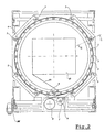
- the machine which actually performs wrapping with the extendable film consists of a ring structure N (which can be seen in Fig. 1 in the raised position) mounted so as to slide vertically on the bridge frame P and raised and lowered by means of a raising system operated by a motor M.
- the annular structure N consists of a pair of annular rims - a lower one 1 and upper one 2 - which are fixed together by a set of pins arranged along an ideal circular line, on which there rotate rollers 3 mounted idle between said rims 1 and 2 which thus form an annular support for said rollers.
- the two rims 1 and 2 are guided on a guiding frame 4 so that they are free to rotate in their plane.
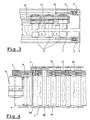
- the guiding frame 4 comprises a set of wheels 5, in particular eight wheels 5 (Fig. 3), which are arranged uniformly along the perimeter of the rims 1 and 2 and on which the annular structure N is supported, being free to rotate.
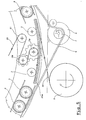
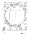
- An endless belt 6 extends over the rollers 3, on the outside thereof, embracing the entire set of rollers 3 as shown in Fig. 3, and also traveling over a driving pulley 7 of a power motor 8 (Figs. 4 and 5) arranged on the outside of the annular structure N.
- an epicycloidal transmission system in which the planetary gears are the rollers 3, the spider consists of the combined arrangement of the two rims 1 and 2, and the belt 6 forms the driving gear; the movement of the belt 6 is transmitted to the rollers 3 and to the rims 1 and 2 by suitably adjusting the resistance to the movement offered by them: should, for example, the two rims 1 and 2 be stopped, the movement of the belt would be converted totally into a rotation of the rollers 3 about their axes and, vice versa, if rotation of the rollers 3 were blocked, the movement of the belt 6 would produce rotational driving of the two rims 1 and 2 together with the rollers fixed thereto.
- rollers 3 - the roller 3a - is rubberized and is coupled with a corresponding rubberized roller 3b, arranged at a short distance from the roller 3a and further internally with respect to the ideal circular line described by the set of rollers (Fig. 5).
- These two rollers 3a and 3b form a pre-stretching unit, which was discussed in detail above, having a well known configuration.
- they are connected by means of a gear-type coupling arrangement which provides a transmission ratio such that the roller 3b rotates at a greater speed than the roller 3a.
- a bobbin 9 of extendable plastic film is mounted, externally with respect to the ring structure N, on a suitable support (not shown) which allows free rotation thereof.
- an end of the film 10 is passed onto the roller 3a and then, in the opposite direction of rotation, onto the roller 3b as well, and, by means of a transmission roller 11, is guided finally, with automatic gripper systems of the known type, which we shall not consider here, onto the product to be wrapped.
- the film 10 does not interfere with the belt 6 since the latter adheres to a upper portion of the rollers 3 (as can be clearly seen in Fig. 4), whereas the film adheres to the remaining portion thereof.
- the belt 6 causes rotation of the annular structure N which, in turn, causes rotation, about the product C, of the point where the extendable film 10 is released - which corresponds to the position of the transmission roller 11 - performing the desired winding action.
- the spiral path of the point where the film adheres onto the product C is obtained by combining the rotary movement of the annular structure N with vertical translation thereof on the bridge frame P.
- the epicycloidal system described has a fairly important characteristic feature, namely it constitutes a superb self-adjusting mechanism for the feeding tension of the film 10.
- the feeding tension of a greater quantity of film is required, resulting in an increase in the tension exerted thereon.
- the increase in tension immediately produces an equal and opposite reaction on the transmission roller 11 and on the pre-stretching unit, resulting in a braking action on the annular structure N.
- This equilibrium condition is typical of the particular working condition of the epicycloidal system, in particular the internal friction of the system and speed of the belt 6, and therefore may be regulated, for example, by suitably adjusting the braking system mentioned above.
- the ideal braking condition is the one where, with practically zero tension, i.e. where no film is required, there is also no feeding of the film, namely rotation of the annular structure occurs exclusively without rotation of the rollers.
- Another fairly interesting aspect of the wrapping machine for pallets according to the invention consists in the fact that, since the bobbin is mounted externally of the annular structure, it unwinds the film both onto the product C and onto the perimeter of the annular structure itself.
- the maximum thickness which the strip 10a may assume is 10 mm, which, for a diameter of 2 m typical of the annular structure N, means a variation in length of 1 % between the innermost ring and the outermost ring. This variation is entirely negligible, in terms of the behaviour of the strip 10a, for a material which is able to undergo elongation of up to 300%.
- the latter are preferably connected together, for example either by means of a series of short belts 12 which connect each roller 3 to the next one, or via a single peripheral belt when the perimeter to be embraced is small.
- These short belts 12 are preferably arranged on the upper portion of the rollers 3, underneath the drive belt 6. This arrangement also allows the movement to be transferred to the feed roller 3a, and hence to the pre-stretching unit, when the feed roller is located in the position illustrated in Fig. 5, i.e. at a position where it is not affected by the direct action of the belt 6.
- the internal diameter of the annular structure N shall be greater than about 1900 mm and its maximum dimension may be easily contained within 2300 mm, compared to the 2500 - 2600 mm of pallet wrapping machines constructed in accordance with the known art: this means that the entire machine may be loaded into the storage container of a lorry (width 2400 mm) without having to disassemble and reassemble the machine at its destination.
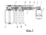
- a pallet wrapping machine which is simplified compared to the one described above, i.e. in which the bobbin is mounted fixed to the annular support defined by the two circular rims 1 and 2 (Figs. 6 and 7), is provided.
- the bobbin 9 there is no longer a relative movement between the bobbin 9 and the rims which results in the film being wound gradually onto the external perimeter of the rollers 3. Therefore, in the absence of the accumulating function of these rollers 3, it is no longer necessary for them to have a length at least equivalent to the height of the film, but it is sufficient for them to have an adequate length for engagement with the short belts 12.
- the bobbin is mounted entirely in cantilever fashion, projecting perpendicularly from one of the two annular rims, and likewise the rollers of the pre-stretching unit also project from the same side.
- This solution involves an advantageous constructional simplification, which consists in a greater lightness of the annular structure and in a reduction in costs, even though it means having to dispense with some of the advantages described above, including the possibility of creating an accumulation of film, so as to allow more efficient changing of the bobbin, and the elimination of eccentric masses, so as to lighten the supporting structure.
- the driving belt 6 could be replaced by a crown gear which engages, internally, with the rollers provided with pinions and, externally, with a driving pinion made to rotate by the motor 8.
Landscapes
- Engineering & Computer Science (AREA)
- Mechanical Engineering (AREA)
- Basic Packing Technique (AREA)
- Pallets (AREA)
- Pharmaceuticals Containing Other Organic And Inorganic Compounds (AREA)
- Liquid Crystal Substances (AREA)
- Steroid Compounds (AREA)
Claims (15)
- Einwickelmaschine für Paletten der Bauart, die einen feststehenden Rahmen (P) umfaßt, auf dem eine ringförmige Struktur (N) angebracht ist, die ein Produkt (C) umgibt, das mit einem Film (10) aus Kunststoffmaterial zu umwickeln ist, das von einer Spule abgewikkelt wird, mit:einem ringförmigen Träger (1, 2), der in seiner Ebene mittels eines Antriebselements (6) rotiert, undeinem Satz von Rollen (3), die drehbar auf parallelen Achsen angebracht und durch den ringförmigen Träger (1, 2) entlang einer kreisförmigen Linie getragen sind, auf die der Film geführt wird, wobei eine der Rollen (3a) eine Zuführungsrolle ist, die dazu bestimmt ist, den Film nach innen bezüglich der ringförmigen Struktur (N) abzugeben, dadurch gekennzeichnet, daß die ringförmige Struktur (N) in Bezug auf das Produkt (C) verlagerbar ist und daß das Antriebselement (6) die Rollen (3) zumindest teilweise umgreift, wobei es gegen deren Umfang anliegt, und dazu bestimmt ist, eine Drehung der Rollen (3) und deren Rotation um die Mittelachse der ringförmigen Struktur (N) zu bewirken, wobei der ringförmige Träger (1, 2), der Satz von Rollen (3) und das Antriebselement (6) das Radialarmteil, die Planetenzahnräder und das Antriebszahnrad eines epizykloidischen Getriebes bilden.
- Einwickelmaschine für Paletten nach Anspruch 1, dadurch gekennzeichnet, daß das Antriebselement ein endloser Gurt (6) ist, der durch eine Antriebseinrichtung in Form einer Riemenscheibe (7) angetrieben ist.
- Einwickelmaschine für Paletten nach Anspruch 1 oder 2, dadurch gekennzeichnet, daß eine Vorstreckeinheit (3a, 3b) auf dem ringförmigen Träger (1, 2) angeordnet ist, um gestreckten Film zu dem Produkt (C) zuzuführen.
- Einwickelmaschine für Paletten nach Anspruch 3, dadurch gekennzeichnet, daß die Vorstreckeinheit eine erste Rolle (3a) aufweist, die mit der Zuführungsrolle (3a) des genannten Satzes von Rollen (3) zusammenfällt, und zumindest eine weitere zweite Rolle (3b) aufweist, die in einem geringen Abstand voneinander angeordnet und mechanisch mit einem Übertragungsverhältnis verbunden sind, so daß sich die zweite Rolle (3b) mit einer größeren Drehzahl als die erste Rolle (3a) dreht, wobei der streckbare Film (10) eine Verlängerung erfährt, wenn er von der ersten Rolle (3a) zu der zweiten Rolle (3b) gelangt.
- Einwickelmaschine für Paletten nach einem der Ansprüche 1 bis 3, weiter gekennzeichnet durch ein Bremssystem, das entweder auf den ringförmigen Träger (1, 2) oder auf die Rollen (3) wirkt.
- Einwickelmaschine nach einem der vorangehenden Ansprüche, dadurch gekennzeichnet, daß der ringförmige Träger ein Paar paralleler, ringförmiger Reifen (1, 2) aufweist, zwischen denen die Rollen(3) drehbar gehalten sind.
- Einwickelmaschine für Paletten nach Anspruch 6, dadurch gekennzeichnet, daß das Bremssystem auf zumindest einen der genannten Reifen wirkt.
- Einwickelmaschine für Paletten nach einem der vorangehenden Ansprüche, dadurch gekennzeichnet, daß die Rollen (3) durch wechselweise Verbindungseinrichtungen drehsynchronisiert sind.
- Einwickelmaschine für Paletten nach Anspruch 8, dadurch gekennzeichnet, daß die wechselweisen Verbindungseinrichtungen kurze Gurte (12) sind, die die Rollen (3) untereinander verbinden.
- Einwickelmaschine für Paletten nach Anspruch 9, dadurch gekennzeichnet, daß der endlose Antriebsgurt (6) die Rollen (3) umgreift, die gegen die kurzen Gurte (12) anliegen.
- Einwickelmaschine für Paletten nach einem der vorangehenden Ansprüche, dadurch gekennzeichnet, daß die ringförmige Struktur (N) durch eine Anzahl von Stützrädern (5) geführt ist, die entlang ihres Umfangs verteilt und auf einem verlagerbaren Führungsrahmen (4) drehbar gehalten sind.
- Einwickelmaschine für Paletten nach Anspruch 11, dadurch gekennzeichnet, daß die Antriebseinrichtung (7), die das Antriebselement (6) antreibt, und eine Spule (9), die den Film (10) liefert, außerhalb der ringförmigen Struktur (N) auf dem Führungsrahmen (4) angeordnet sind.
- Einwickelmaschine für Paletten nach Anspruch 12, dadurch gekennzeichnet, daß die Rollen (3) eine Länge aufweisen, die zumindest gleich der Höhe des Films (10) ist.
- Einwickelmaschine für Paletten nach einem der Ansprüche 1 bis 11, dadurch gekennzeichnet, daß die Antriebseinrichtung (7), die das Antriebselement (6) antreibt, außerhalb der ringförmigen Struktur (N) angebracht ist, und die Spule (9), die den Film liefert, auf dem ringförmigen Träger (1, 2) angebracht ist.
- Einwickelmaschine für Paletten nach Anspruch 14, dadurch gekennzeichnet, daß die Spule (9) fliegend gelagert ist und von einer Seite des ringförmigen Trägers (1, 2) vorsteht, wobei lediglich die Rollen (3a, 3b), die die Vorstreckeinheit bilden, sich über eine Länge erstrecken, die zumindest gleich der Höhe des streckbaren Films (10) ist.
Applications Claiming Priority (3)
| Application Number | Priority Date | Filing Date | Title |
|---|---|---|---|
| IT96MI002394A IT1287108B1 (it) | 1996-11-18 | 1996-11-18 | Fasciapallet epicicloidale |
| ITMI962394 | 1996-11-18 | ||
| PCT/EP1997/003628 WO1998022346A1 (en) | 1996-11-18 | 1997-07-09 | Epicycloidal wrapping machine for pallets |
Publications (2)
| Publication Number | Publication Date |
|---|---|
| EP0938428A1 EP0938428A1 (de) | 1999-09-01 |
| EP0938428B1 true EP0938428B1 (de) | 2000-10-18 |
Family
ID=11375232
Family Applications (1)
| Application Number | Title | Priority Date | Filing Date |
|---|---|---|---|
| EP97935515A Expired - Lifetime EP0938428B1 (de) | 1996-11-18 | 1997-07-09 | Epizycloidale einwickelmaschine für paletten |
Country Status (6)
| Country | Link |
|---|---|
| EP (1) | EP0938428B1 (de) |
| AT (1) | ATE197027T1 (de) |
| DE (1) | DE69703359T2 (de) |
| ES (1) | ES2151291T3 (de) |
| IT (1) | IT1287108B1 (de) |
| WO (1) | WO1998022346A1 (de) |
Cited By (1)
| Publication number | Priority date | Publication date | Assignee | Title |
|---|---|---|---|---|
| IT201800010782A1 (it) * | 2018-12-04 | 2020-06-04 | Aetna Group Spa | Macchina avvolgitrice |
Families Citing this family (25)
| Publication number | Priority date | Publication date | Assignee | Title |
|---|---|---|---|---|
| US7568327B2 (en) | 2003-01-31 | 2009-08-04 | Lantech.Com, Llc | Method and apparatus for securing a load to a pallet with a roped film web |
| ITBO20050191A1 (it) * | 2005-03-25 | 2006-09-26 | Atlanta Stretch S P A | Macchina ad anello per la fasciatura veloce di carichi ugualmente pallettizzati con film estensibile svolto da una bobina in posizione statica e di grande autonomia |
| US7707801B2 (en) | 2005-04-08 | 2010-05-04 | Lantech.Com, Llc | Method for dispensing a predetermined amount of film relative to load girth |
| EP2607244A3 (de) | 2006-02-23 | 2014-12-03 | Lantech.Com, Llc | Ringverpackungsvorrichtung mit Anordnung zur abgemessenen Ausgabe eines vorgedehnten Films |
| ITMO20060221A1 (it) * | 2006-07-07 | 2008-01-08 | Aetna Group Spa | Macchina avvolgitrice e metodi di avvolgimento |
| AU2009204214B2 (en) | 2008-01-07 | 2014-05-22 | Lantech.Com, Llc | Electronic control of metered film dispensing in a wrapping apparatus |
| US9908648B2 (en) | 2008-01-07 | 2018-03-06 | Lantech.Com, Llc | Demand based wrapping |
| EP2865600B1 (de) | 2010-10-29 | 2016-07-13 | Lantech.Com LLC | Verfahren zur Erzeugung von Daten während der Verpackung einer Last sowie Verpackungsmaschine |
| US20130077910A1 (en) * | 2011-09-23 | 2013-03-28 | Siemens Industry, Inc. | High speed mechanical bearing using fixed rollers |
| CA2818145C (en) | 2012-06-08 | 2021-01-05 | Wulftec International Inc. | Apparatuses for wrapping a load and supplying film for wrapping a load and associated methods |
| WO2014066778A1 (en) | 2012-10-25 | 2014-05-01 | Lantech.Com, Llc | Corner geometry-based wrapping |
| WO2014066757A1 (en) | 2012-10-25 | 2014-05-01 | Lantech.Com, Llc | Rotation angle-based wrapping |
| CA3109066C (en) | 2012-10-25 | 2023-03-07 | Lantech.Com, Llc | Effective circumference-based wrapping |
| EP3301032B1 (de) | 2013-02-13 | 2019-05-01 | Lantech.Com LLC | Umfassungskraftbasiertes umwickeln |
| CA3202951A1 (en) | 2014-01-14 | 2015-07-23 | Lantech.Com, Llc | Dynamic adjustment of wrap force parameter responsive to monitored wrap force and/or for film break reduction |
| EP3204298B1 (de) | 2014-10-07 | 2019-04-24 | Lantech.Com LLC | Grafische darstellung eines umwicklungsprofils für eine umwicklungsvorrichtung |
| WO2017053608A1 (en) | 2015-09-25 | 2017-03-30 | Lantech.Com, Llc | Stretch wrapping machine with automated determination of load stability by subjecting a load to a disturbance |
| CN106962963B (zh) * | 2017-05-03 | 2023-06-02 | 连云港瑞洋牧业有限公司 | 发酵饲草的生产系统 |
| SMT202300435T1 (it) | 2017-09-22 | 2024-01-10 | Lantech Com Llc | Profili di imballaggio di un dispositivo di imballaggio di carichi con interruzioni controllate del ciclo di imballaggio |
| CN108327951A (zh) * | 2017-12-23 | 2018-07-27 | 安徽耐科挤出科技股份有限公司 | 齿轮传动式型材缠绕捆扎机构 |
| AU2019319726B2 (en) | 2018-08-06 | 2022-04-07 | Lantech.Com, Llc | Stretch wrapping machine with curve fit control of dispense rate |
| ES2946013T3 (es) | 2018-12-04 | 2023-07-11 | Aetna Group Spa | Método y aparato para envolver una carga y máquina de envolver |
| CA3147094C (en) | 2019-09-09 | 2025-02-11 | Lantech.Com, Llc | Shrink wrapper with speed control based on the detected speed of the dispensed packaging material and the predicted load geometry |
| AU2020350496B2 (en) | 2019-09-19 | 2024-01-25 | Lantech.Com, Llc | Packaging material grading and/or factory profiles |
| CN116477101B (zh) * | 2023-06-21 | 2023-08-25 | 广州市鸿大胶粘制品有限公司 | 一种薄膜绕包装置 |
Family Cites Families (4)
| Publication number | Priority date | Publication date | Assignee | Title |
|---|---|---|---|---|
| GB670737A (en) * | 1948-07-19 | 1952-04-23 | Albert Earl Cranston Sr | Bundle binding machine |
| US2749837A (en) * | 1950-09-26 | 1956-06-12 | John T Hayford | Bundle packaging and wrapping machine |
| IT1227424B (it) * | 1988-11-15 | 1991-04-11 | Danieli Off Mecc | Legatrice con distributore rotante per fasci di barre metalliche |
| US5027581A (en) * | 1990-05-30 | 1991-07-02 | Hayssen Manufacturing Company | Wrapping method and apparatus |
-
1996
- 1996-11-18 IT IT96MI002394A patent/IT1287108B1/it active IP Right Grant
-
1997
- 1997-07-09 WO PCT/EP1997/003628 patent/WO1998022346A1/en not_active Ceased
- 1997-07-09 DE DE69703359T patent/DE69703359T2/de not_active Expired - Fee Related
- 1997-07-09 ES ES97935515T patent/ES2151291T3/es not_active Expired - Lifetime
- 1997-07-09 AT AT97935515T patent/ATE197027T1/de not_active IP Right Cessation
- 1997-07-09 EP EP97935515A patent/EP0938428B1/de not_active Expired - Lifetime
Cited By (1)
| Publication number | Priority date | Publication date | Assignee | Title |
|---|---|---|---|---|
| IT201800010782A1 (it) * | 2018-12-04 | 2020-06-04 | Aetna Group Spa | Macchina avvolgitrice |
Also Published As
| Publication number | Publication date |
|---|---|
| IT1287108B1 (it) | 1998-08-04 |
| EP0938428A1 (de) | 1999-09-01 |
| DE69703359D1 (de) | 2000-11-23 |
| WO1998022346A1 (en) | 1998-05-28 |
| ATE197027T1 (de) | 2000-11-15 |
| ES2151291T3 (es) | 2000-12-16 |
| ITMI962394A0 (it) | 1996-11-18 |
| DE69703359T2 (de) | 2001-05-17 |
| ITMI962394A1 (it) | 1998-05-18 |
Similar Documents
| Publication | Publication Date | Title |
|---|---|---|
| WO1998022346A1 (en) | Epicycloidal wrapping machine for pallets | |
| EP2463202B1 (de) | Umwicklungsmaschine | |
| US9187193B2 (en) | Method and apparatus for dispensing an amount of film relative to girth | |
| US6748718B2 (en) | Method and apparatus for wrapping a load | |
| US4953336A (en) | High tensile wrapping apparatus | |
| US4862678A (en) | Constant tension stretch wrapping machine | |
| US4590746A (en) | Constant tension stretch wrapping machine | |
| CN214190246U (zh) | 一种束带机的储带机构 | |
| US4676048A (en) | Supply control rotating stretch wrapping apparatus and process | |
| US5572855A (en) | Stretch wrapping tape dispensing apparatus | |
| EP1213223A1 (de) | Vorrichtung zum abwickeln von dehnbarer Kunststofffolie | |
| US4706443A (en) | Constant tension stretch wrapping machine | |
| CZ289828B6 (cs) | Způsob předběľného protahování filmu a stroj pro předběľné protahování filmu | |
| GB2154537A (en) | Dual rotating stretch wrapping apparatus and process | |
| CA3245456A1 (en) | METHOD AND ASSEMBLY FOR PACKAGING ONE OR MORE PACKAGES WITH STRETCH FILM FROM A ROLL | |
| CA2007970C (en) | Continuously balanced apparatus for storing and dispensing elongate materials | |
| EP0152960B1 (de) | Umlaufende Folienwickelvorrichtung und Verfahren zum Zusammenfassen von Gegenständen mittels eines Einschlusswickels | |
| JP2552330B2 (ja) | 品物の周りに伸長可能なプラスチックフィルムのウエブを巻付ける前に供給リールからのウエブの供給を制御する予備引張装置 | |
| US5575138A (en) | Stretch wrapping tape dispensing apparatus | |
| EP2452881B1 (de) | Vertikale Wickelvorrichtung zum Verpacken von Palettenladungen unterschiedlicher Höhe mit Folien aus Kunststoffmaterial | |
| HK1170203A (en) | Vertical winding apparatus for packaging of pallet loads with films of plastic material of different heights |
Legal Events
| Date | Code | Title | Description |
|---|---|---|---|
| PUAI | Public reference made under article 153(3) epc to a published international application that has entered the european phase |
Free format text: ORIGINAL CODE: 0009012 |
|
| 17P | Request for examination filed |
Effective date: 19990527 |
|
| AK | Designated contracting states |
Kind code of ref document: A1 Designated state(s): AT BE CH DE DK ES FI FR GB GR IE IT LI LU NL PT SE |
|
| GRAG | Despatch of communication of intention to grant |
Free format text: ORIGINAL CODE: EPIDOS AGRA |
|
| 17Q | First examination report despatched |
Effective date: 19991118 |
|
| GRAG | Despatch of communication of intention to grant |
Free format text: ORIGINAL CODE: EPIDOS AGRA |
|
| GRAH | Despatch of communication of intention to grant a patent |
Free format text: ORIGINAL CODE: EPIDOS IGRA |
|
| GRAH | Despatch of communication of intention to grant a patent |
Free format text: ORIGINAL CODE: EPIDOS IGRA |
|
| GRAA | (expected) grant |
Free format text: ORIGINAL CODE: 0009210 |
|
| AK | Designated contracting states |
Kind code of ref document: B1 Designated state(s): AT BE CH DE DK ES FI FR GB GR IE IT LI LU NL PT SE |
|
| PG25 | Lapsed in a contracting state [announced via postgrant information from national office to epo] |
Ref country code: NL Free format text: LAPSE BECAUSE OF FAILURE TO SUBMIT A TRANSLATION OF THE DESCRIPTION OR TO PAY THE FEE WITHIN THE PRESCRIBED TIME-LIMIT Effective date: 20001018 Ref country code: LI Free format text: LAPSE BECAUSE OF FAILURE TO SUBMIT A TRANSLATION OF THE DESCRIPTION OR TO PAY THE FEE WITHIN THE PRESCRIBED TIME-LIMIT Effective date: 20001018 Ref country code: IT Free format text: LAPSE BECAUSE OF FAILURE TO SUBMIT A TRANSLATION OF THE DESCRIPTION OR TO PAY THE FEE WITHIN THE PRESCRIBED TIME-LIMIT;WARNING: LAPSES OF ITALIAN PATENTS WITH EFFECTIVE DATE BEFORE 2007 MAY HAVE OCCURRED AT ANY TIME BEFORE 2007. THE CORRECT EFFECTIVE DATE MAY BE DIFFERENT FROM THE ONE RECORDED. Effective date: 20001018 Ref country code: FR Free format text: LAPSE BECAUSE OF FAILURE TO SUBMIT A TRANSLATION OF THE DESCRIPTION OR TO PAY THE FEE WITHIN THE PRESCRIBED TIME-LIMIT Effective date: 20001018 Ref country code: FI Free format text: LAPSE BECAUSE OF FAILURE TO SUBMIT A TRANSLATION OF THE DESCRIPTION OR TO PAY THE FEE WITHIN THE PRESCRIBED TIME-LIMIT Effective date: 20001018 Ref country code: CH Free format text: LAPSE BECAUSE OF FAILURE TO SUBMIT A TRANSLATION OF THE DESCRIPTION OR TO PAY THE FEE WITHIN THE PRESCRIBED TIME-LIMIT Effective date: 20001018 Ref country code: BE Free format text: LAPSE BECAUSE OF FAILURE TO SUBMIT A TRANSLATION OF THE DESCRIPTION OR TO PAY THE FEE WITHIN THE PRESCRIBED TIME-LIMIT Effective date: 20001018 Ref country code: AT Free format text: LAPSE BECAUSE OF FAILURE TO SUBMIT A TRANSLATION OF THE DESCRIPTION OR TO PAY THE FEE WITHIN THE PRESCRIBED TIME-LIMIT Effective date: 20001018 |
|
| REF | Corresponds to: |
Ref document number: 197027 Country of ref document: AT Date of ref document: 20001115 Kind code of ref document: T |
|
| REG | Reference to a national code |
Ref country code: CH Ref legal event code: EP |
|
| REG | Reference to a national code |
Ref country code: IE Ref legal event code: FG4D |
|
| REF | Corresponds to: |
Ref document number: 69703359 Country of ref document: DE Date of ref document: 20001123 |
|
| REG | Reference to a national code |
Ref country code: ES Ref legal event code: FG2A Ref document number: 2151291 Country of ref document: ES Kind code of ref document: T3 |
|
| PG25 | Lapsed in a contracting state [announced via postgrant information from national office to epo] |
Ref country code: SE Free format text: LAPSE BECAUSE OF FAILURE TO SUBMIT A TRANSLATION OF THE DESCRIPTION OR TO PAY THE FEE WITHIN THE PRESCRIBED TIME-LIMIT Effective date: 20010118 Ref country code: PT Free format text: LAPSE BECAUSE OF FAILURE TO SUBMIT A TRANSLATION OF THE DESCRIPTION OR TO PAY THE FEE WITHIN THE PRESCRIBED TIME-LIMIT Effective date: 20010118 Ref country code: DK Free format text: LAPSE BECAUSE OF FAILURE TO SUBMIT A TRANSLATION OF THE DESCRIPTION OR TO PAY THE FEE WITHIN THE PRESCRIBED TIME-LIMIT Effective date: 20010118 |
|
| PG25 | Lapsed in a contracting state [announced via postgrant information from national office to epo] |
Ref country code: GR Free format text: LAPSE BECAUSE OF FAILURE TO SUBMIT A TRANSLATION OF THE DESCRIPTION OR TO PAY THE FEE WITHIN THE PRESCRIBED TIME-LIMIT Effective date: 20010119 |
|
| NLV1 | Nl: lapsed or annulled due to failure to fulfill the requirements of art. 29p and 29m of the patents act | ||
| EN | Fr: translation not filed | ||
| REG | Reference to a national code |
Ref country code: CH Ref legal event code: PL |
|
| PGFP | Annual fee paid to national office [announced via postgrant information from national office to epo] |
Ref country code: ES Payment date: 20010627 Year of fee payment: 5 |
|
| PG25 | Lapsed in a contracting state [announced via postgrant information from national office to epo] |
Ref country code: LU Free format text: LAPSE BECAUSE OF NON-PAYMENT OF DUE FEES Effective date: 20010709 Ref country code: IE Free format text: LAPSE BECAUSE OF NON-PAYMENT OF DUE FEES Effective date: 20010709 Ref country code: GB Free format text: LAPSE BECAUSE OF NON-PAYMENT OF DUE FEES Effective date: 20010709 |
|
| PLBE | No opposition filed within time limit |
Free format text: ORIGINAL CODE: 0009261 |
|
| STAA | Information on the status of an ep patent application or granted ep patent |
Free format text: STATUS: NO OPPOSITION FILED WITHIN TIME LIMIT |
|
| 26N | No opposition filed | ||
| PGFP | Annual fee paid to national office [announced via postgrant information from national office to epo] |
Ref country code: DE Payment date: 20020129 Year of fee payment: 5 |
|
| GBPC | Gb: european patent ceased through non-payment of renewal fee |
Effective date: 20010709 |
|
| REG | Reference to a national code |
Ref country code: IE Ref legal event code: MM4A |
|
| PG25 | Lapsed in a contracting state [announced via postgrant information from national office to epo] |
Ref country code: ES Free format text: LAPSE BECAUSE OF NON-PAYMENT OF DUE FEES Effective date: 20020710 |
|
| PG25 | Lapsed in a contracting state [announced via postgrant information from national office to epo] |
Ref country code: DE Free format text: LAPSE BECAUSE OF NON-PAYMENT OF DUE FEES Effective date: 20030201 |
|
| REG | Reference to a national code |
Ref country code: ES Ref legal event code: FD2A Effective date: 20030811 |