BACKGROUND OF THE INVENTION
-
The present invention relates to a failure detecting
system for an automatic transmission of a vehicle employing
an engine rotational speed, a cruise control signal, a
brake signal from a brake switch or a shift range switch
operation signal from a shift range switch as one of
control signals to control the automatic transmission.
-
An automatic transmission AT is fundamentally
controlled to be shifted by regulating depression of an
accelerator pedal and a traveling speed of a vehicle.
Accordingly, in case where the vehicle travels in a drive
(D) range, reduction gears can be shifted by positively
depressing or releasing the accelerator pedal.
-
In a conventional automatic transmission, for example,
in a drive (D) range, an optimum gear is selectively
controlled from a vehicle speed at that time and a throttle
opening according to a shift map storing a predetermined
shift schedule as shown in Fig. 14.
-
As a lockup function of an automatic transmission a
lockup clutch is engaged when a vehicle speed becomes
higher than a predetermined value in a certain gear
position such as, for example, in a third gear or an
overdrive (fourth gear), to directly couple an output shaft
of a torque converter to an output shaft of an engine. In
other cases, the lockup clutch is released to connect the
input shaft of the torque converter to the output shaft of
the engine.
-
The lockup is released to utilize a function of the
torque converter thereby to achieve smooth starting, smooth
accelerating or smooth speed shifting without engine
knocking or stop at the time of starting, abruptly
accelerating, speed shifting the vehicle.
-
However, in a state that a load is low and an engine
rotational speed is high, the torque converter is locked up
thereby to prevent loss of power due to a slip of the
torque converter and hence to prevent a decrease in fuel
consumption.
-
A cruise control unit so controls an opening of a
throttle valve as to maintain a certain vehicle speed set
by a driver as a desired traveling speed thereby
controlling in response to a road state.
-
As the typical automatic transmission control to
execute as described above, Japanese Utility Model
Application Laid-Open 63-115558 discloses an internal
combustion engine with an abnormality detector for judging
an abnormality based on a rotational signal from a rotation
detector for electrically detecting a rotational speed of
the internal combustion engine and a fuel amount signal
from a fuel amount detector for detecting a fuel supply
amount to the internal combustion engine.
-
In the above-described internal combustion engine with
the abnormality detector, it is determined that an engine
rotational speed signal line is when an engine rotational
speed is smaller than a predetermined value at a certain
vehicle speed or more. However, even if an engine stop
occurs at a certain vehicle speed or more, it is
erroneously detected that the failure occurs at the engine
rotational speed signal line.
-
In such a case, it becomes impossible to detect a
failure of an ignition pulse generating an engine
rotational speed detection signal to be supplied to the
engine rotational speed signal line. Furthermore, there
are disadvantages that the automatic transmission control
based on the engine rotational speed such as, for example,
a gear shift control, a lockup control, a line pressure
control can not be appropriately controlled.
-
As the typical automatic transmission control to
execute as described above, Japanese Utility Model
Application Laid-Open 63-137038 discloses an automatic
transmission controller in which hunting of the vehicle
speed due to a gear shifting during a cruise control
traveling is prevented and a fail-safe control is performed
when an abnormality of an automatic transmission occurs.
-
More specifically, the automatic transmission
controller additionally provides a memory map storing a
shift schedule for controlling the automatic transmission
in response to a cruise control signal supplied from a
cruise controller, in which map a hysteresis width is so
set as to reduce the number of repetitions of down and up
shifting.
-
In this case, since the number of times of gear
shifting during the cruise control is reduced, hunching of
the vehicle speed due to the gear shifting can be
prevented, and a riding comfort can be improved.
-
In the conventional automatic transmission controller
as described above, a vehicle can be traveled smoothly
without shock in the case of shifting gear during the
cruise control, but it does not have a fail-safe function
in case where the cruise control signal is, for example,
erroneously generated even though the cruise control is not
performed by the cruise controller.
-
Usually, the automatic transmission controller
functions a gear shifting control, a lockup control,
an overrunning clutch control (namely, engine brake
control), etc. Therefore, if a fail-safe function is not
provided, these functions are erroneously operated when a
cruise control signal is erroneously generated.
-
In a conventional automatic transmission, for example,
in a drive (D) range, an optimum gear is selected based on
a vehicle speed and a throttle opening at that time, from a
shift schedule map storing a predetermined shift schedule
as shown in Fig. 14.
-
Further, in such an automatic transmission control,
detection signals from various detecting sensors are input
to a controller to perform a lockup control, an overrunning
clutch control, a line pressure control, an auto-pattern
select control, a gear shift timing control, a transfer
clutch control of four-wheel drive as well as the above-described
gear shift control are executed.
-
Japanese Patent Application Laid-Open 1-145234
discloses a cruise control of a vehicle using a brake
switch signal.
-
More specifically, as shown in Fig. 15, a detection
signal SG1 from a vehicle speed sensor is input to a cruise
controller 1. When a check switch 4 is turned on, a CPU 5
enters in an input waiting state of a brake switch signal
SG2. When a brake pedal is once depressed and then
released, the CPU 5 decides that a series of ON/OFF signals
of the brake switch 3 are input. In this case, a cruise
control allowance flag is set, while in case the CPU 5
decides no input of the series of signals, the CPU 5 does
not set the cruise control allowance flag.
-
Then, whether the cruise control is requested by
various switches 6 for the cruise control or not is
decided. In case where the cruise control is requested,
whether the cruise control allowance flag is set or not is
decided, and in case the flag is set, the cruise control
is executed.
-
In case where the cruise control allowance flag is not
set, a warning light is turned on to inform the gist, and
cruise control is prohibited.
-
Thus, in such a cruise control unit for a vehicle, an
error of the brake switch 3 is checked previously by the
check switch 4 for requesting a signal check of the brake
switch 3 before the cruise control. Therefore, the
cruise control can be reliably executed by the brake switch
3.
-
However, in the above-described conventional cruise
control unit for a vehicle, the check switch 4 is
additionally needed to check the brake switch 3, thereby
causing a complicated structure.
-
Since the brake switch 3 is checked by the operation
of the check switch 4 only before the cruise control, there
is a disadvantage that the brake switch 3 cannot be
checked, in case where the cruise control is not executed.
Moreover, a failure of the brake switch is not executed
when a braking operation is required in various running
states of the vehicle such as, for example, at the time of
decelerating.
-
Further, a shift lever for operating a range shift of
an automatic transmission is connected to an inhibitor
switch having a plurality of switches corresponding to the
number of operating positions. When a range is selected by
the operation of the shift lever, the corresponding switch
generates a first level electric signal. Other switches
not selected by the shift lever generate second level
signals.
-
The positions of the shift lever includes, generally
in the case of a four-speed automatic transmission, R
(reverse), N (neutral), D (drive), 3 (third), 2 (second), L
(low) and P (parking) of seven positions. The inhibitor
switch for indicating the position of the shift lever
includes seven switches each of which is closed (first
level) when the corresponding position of the R, N, D, 3,
2, 1, L or P is selected by the shift lever, and opened
(second level) when different positions are selected.
-
On the contrary, the inhibitor switch may include
switches each of which opened in the case of the
corresponding shift position and closed in the case of the
different positions.
-
Therefore, any one of the seven switches is normally
closed (opened) and the residual six switches are opened
(closed). However, if at least one of the switches is
troubled, or if an abnormality occurs at an interlocking
member for operating to open or close the switch in
cooperation with the shift lever, two or more switches
might be simultaneously closed (opened), or all the
switches might be simultaneously opened (closed). Such an
abnormality causes an error in an automatic transmission
control.
-
Switch might be, for example, instantaneously
repeatedly opened/closed in an extremely short time due to
a chattering when the switch is changed from open to close
or vice versa. Further, in case where a mechanical member
moves to sequentially close (open) one of the switches
aligned in a moving direction of the mechanical member, the
adjacent two switches might be simultaneously closed
(opened) at a certain time point. This is normal.
However, if it is conditioned to detect as an abnormality
when two or more switches are simultaneously closed or all
the switches are simultaneously opened, such a normal case
as described above that the adjacent two switches are
simultaneously closed, is erroneously determined as an
abnormality.
-
With respect to this, Japanese Patent Application
Laid-Open 63-34349 discloses a method for detecting a
trouble of a gear position switch. That is, if a gear
position switch does not generate an ON signal when a
predetermined time is elapsed after a gear shifting is
performed, it is returned to a position before the gear
changing, and when the same operation as above is conducted
predetermined times or more, the switch is decided to be a
trouble.
-
However, in the above-described conventional method
for detecting the trouble of the gear position switch, in
case where the ON signal is not generated from the gear
position switch, the gear is returned to the position
before the gear shifting, and when the same operation as
above is again conducted predetermined times or more, the
switch is decided to be the trouble. Therefore, in the
case of the trouble, it merely controls to return the
position of the switch to the position before the gear
shifting, an accurate automatic transmission control
responsive to various traveling states of the vehicle is
impossible.
SUMMARY OF THE INVENTION
-
An object of the present invention is to provide a
failure detecting system for an engine rotational signal
line connected to a controller for an automatic
transmission of a vehicle which can reliably detect a
failure of the engine rotational signal line thereby to
appropriately control an operation of an automatic
transmission control based on an engine rotational speed.
-
In order to achieve the above object, the present
invention provides a failure detecting system for engine
rotational signal line of an automatic transmission of a
vehicle employing an engine rotational speed as one of
control signals to control said automatic transmission, the
system comprising:
- engine speed detecting means for detecting said engine
rotational speed;
- air amount detecting means for detecting an amount of
induction air; and
- transmission control prohibiting means for prohibiting
a transmission control based on said engine rotational
speed, when said amount of induction air detected by said
air amount detecting means is larger than a predetermined
value, and when said engine rotational speed detected by
said engine speed detecting means continues to be smaller
than a predetermined value for more than a predetermined
time.
-
-
The present invention also provides a failure
detecting system for an engine rotational signal line of an
automatic transmission of a vehicle employing an engine
rotational speed as one of input signals to control said
automatic transmission, the system comprising:
- engine speed detecting means for detecting said engine
rotational speed;
- air amount detecting means for detecting an amount of
induction air;
- vehicle speed detecting means for detecting a vehicle
speed; and
- transmission control prohibiting means for prohibiting
a transmission control based on said engine rotational
speed, when said vehicle speed detected by said vehicle
speed detecting means is larger than a predetermined value,
when said amount of induction air detected by said air
amount detecting means is larger than a predetermined
value, and when said engine rotational speed detected by
said engine speed detecting means continues to be smaller
than a predetermined value for more than a predetermined
time.
-
-
The present invention also provides a failure
detecting system for an engine rotational speed signal line
connected to a controller for an automatic transmission of
a vehicle employing an engine rotational speed as one of
input signals to control the automatic transmission, the
system comprising:
- engine speed detecting means for detecting said engine
rotational speed;
- fuel injection amount detecting means for detecting a
fuel injection amount; and
- transmission control prohibiting means for prohibiting
a transmission control based on said engine rotational
speed, when said fuel injection amount detected by said
fuel injection amount detecting means is larger than a
predetermined value, and when said engine rotational speed
detected by said engine speed detecting means continues to
be smaller than a predetermined value for more than a
predetermined time.
-
-
The present invention also provides a failure
detecting system for an engine rotational signal line of an
automatic transmission of a vehicle employing an engine
rotational speed as one of control signals to control said
automatic transmission, the system comprising:
- engine speed detecting means for detecting said engine
rotational speed;
- vehicle speed detecting means for detecting a vehicle
speed;
- fuel injection amount detecting means for detecting a
fuel injection amount; and
- transmission control prohibiting means for prohibiting
a transmission control based on said engine rotational
speed, when said vehicle speed detected by said vehicle
speed detecting means is larger than a predetermined value,
when said fuel injection amount detected by said fuel
injection amount detecting means is larger than a
predetermined value, and when said engine rotational speed
detected by said engine speed detecting means continues to
be smaller than a predetermined value for more than a
predetermined time.
-
-
According to the failure detecting system for the
engine rotational signal speed line of the present
invention, the automatic transmission control of the
automatic transmission AT is prohibited in case where one
of the following conditions is satisfied.
-
- (1) When the amount of intake air is larger than a
predetermined value, the state that the engine rotational
speed is smaller than a predetermined value is continued
for a predetermined time.
- (2) When the vehicle speed is larger than a predetermined
value, the amount of intake air is larger than a
predetermined value and the state that the engine
rotational speed is smaller than a predetermined state
is continued for a predetermined time.
- (3) When the fuel injection amount is larger than a
predetermined value, the state that the engine
rotational speed is smaller than a predetermined value
is continued for a predetermined time.
- (4) When the vehicle speed is larger than a predetermined
value, the fuel injection amount is larger than a
predetermined value and the state that the engine
rotational speed is smaller than a predetermined value is
continued for a predetermined time.
-
-
In case where any of the above conditions (1) to (4)
is satisfied, it is determined that a failure occurs on the
engine rotational speed signal line, whereby the automatic
transmission control based on the engine rotational speed
is prohibited, and the state before the failure is detected
is maintained.
-
Another object of the present invention is to provide
a failure detecting system for a cruise control set signal
line connected to a controller for an automatic
transmission of a vehicle which can reliably detect a
failure of a cruise control set signal line thereby to
appropriately control an operation of an automatic
transmission control in response to a cruise control
signal.
-
In order to achieve the another object of the present
invention, there is provided a failure detecting system for
an automatic transmission of a vehicle employing a cruise
control signal as one of input signals to control said
automatic transmission, the system comprising:
- vehicle speed detecting means for detecting a vehicle
speed;
- cruise control signal generating means for generating
a cruise control signal so as to instruct a cruise control
to said automatic transmission; and
- transmission control prohibiting means for prohibiting
a transmission control based on said cruise control signal,
when said vehicle speed detected by said vehicle speed
detecting means is smaller than a predetermined value below
which said cruise control is prohibited, and when said
cruise control signal is generated from said cruise control
signal generating means.
-
-
The present invention also provides a failure
detecting system for an automatic transmission of a vehicle
employing a cruise control signal as one of input signals
to control said automatic transmission, the system
comprising:
- brake signal generating means for generating a brake
signal when a brake switch is turned on;
- cruise control signal generating means for generating
a cruise control signal so as to instruct a cruise control
to said automatic transmission; and
- transmission control prohibiting means for prohibiting
a transmission control based on said cruise control signal,
when said brake signal is generated from said brake signal
generating mean, and when said cruise control signal is
generated from said cruise control signal generating means.
-
-
The present invention also provides a failure
detecting system for an automatic transmission of a vehicle
employing a cruise control signal as one of control signals
to control said automatic transmission, the system
comprising:
- cruise control signal generating means for generating
a cruise control signal so as to instruct a cruise control
to said automatic transmission;
- shift signal generating means for generating a shift
signal so as to instruct an appropriate gear position to
said automatic transmission; and
- transmission control prohibiting means for prohibiting
a transmission control based on said cruise control signal,
when said shift signal from said shift signal generating
means indicates a parking (P) or reverse (R) range, and
when said cruise control signal is generated from said
cruise control signal generating means.
-
-
The present invention also provides the failure
detecting system, wherein
- said transmission control prohibiting means are for
prohibiting a transmission control based on said cruise
control signal, when said vehicle speed detected by said
vehicle speed detecting means is smaller than a
predetermined value below which said cruise control is
prohibited, and when said cruise control signal is
generated from said cruise control signal generating means
for a predetermined time.
-
-
According to the failure detecting system for the
cruise control set signal line of the present invention,
the automatic transmission control of the automatic
transmission AT is prohibited in case where one of the
following conditions is satisfied.
-
- (1) When the cruise control signal is erroneously turned on
in case where a vehicle speed is smaller than a value
under which the operation of a cruise control is not
performed.
- (2) When the cruise control signal which ought to be
released is erroneously turned on at the time of turning
a brake switch on.
- (3) When the cruise control signal is erroneously turned on
in an "N" or "P" range.
- (4) When any of the paragraphs (1) to (3) is continued for
a predetermined time.
-
-
In case where any of the above conditions (1) to (4)
is satisfied, it is determined that a failure occurs on the
cruise control set signal line, whereby the automatic
transmission control at the time of the cruise control is
prohibited. However, a normal state is recovered when an
off signal of the cruise control is detected after one of
the above-described conditions is satisfied.
-
Still another object of the present invention is to
provide a failure detecting system for a brake switch
connected to a controller for an automatic transmission of
a vehicle which can reliably detect a failure of a brake
responsive to various running states thereby to
appropriately control an operation of an automatic
transmission control based on a brake switch signal.
-
The present invention also provides a failure
detecting system for brake switch connected to a controller
for an automatic transmission of a vehicle employing a
brake signal from a brake switch as one of input signals to
control said automatic transmission, the system comprising:
- vehicle speed detecting means for detecting a vehicle
speed;
- brake signal detecting means for detecting a brake
signal when said brake switch is turned on; and
- transmission control prohibiting means for prohibiting
a transmission control based on said brake signal, when a
number of times of how often said brake signal which ought
to be detected has not been detected while said vehicle is
decelerated from a predetermined speed to a zero speed
reaches a predetermined number of times.
-
-
The present invention also provides the failure
detecting system, wherein
- said transmission control prohibiting means are for
prohibiting said transmission control based on said brake
signal, when a deceleration rate of said vehicle obtained
from said vehicle speed detected by said vehicle speed
detecting means, and when a number of times of how often
said brake signal which ought to be detected has not been
detected reaches a predetermined number of times.
-
-
The present invention also provides the failure
detecting system, wherein
- said transmission control prohibiting means are for
prohibiting said transmission control based on said brake
signal, when said vehicle speed detected by said vehicle
speed detecting means is larger than a predetermined speed,
when a deceleration rate of said vehicle obtained from
said vehicle speed detected by said vehicle speed
detecting means is larger than a predetermined value, and
when said brake signal which ought to be detected i not
detected.
-
-
The present invention also provides a failure
detecting system for a brake switch connected to a
controller for an automatic transmission of a vehicle
employing a brake signal from a brake switch as one of
control signals to control said automatic transmission, the
system comprising:
- brake signal detecting means for detecting a brake
signal when said brake switch is turned on;
- shift signal generating means for generating a shift
signal so as to instruct an appropriate gear position to
said automatic transmission; and
- transmission control prohibiting means for prohibiting
a transmission control based on said brake signal, when
said shift signal from said shift signal generating means
indicates a change from a parking (P) range to a reverse
(R) range, and when a number of times of how often said
brake signal which ought to be detected has not been
detected reaches a predetermined number of times.
-
-
According to the failure detecting system for the
brake switch of the present invention, the automatic
transmission control of the automatic transmission AT is
prohibited in case where one of the following conditions
is satisfied.
-
- (1) When a brake ON signal is not detected when the
vehicle speed is decelerated until a vehicle is
stopped, and when this phenomenon occurs continuously
predetermined times.
- (2) When a deceleration of the vehicle speed is larger than
a predetermined value, the brake ON signal is not
detected, and when this phenomenon occurs continuously
predetermined times.
- (3) In case where a vehicle speed is larger than a certain
value, and the paragraph (2) is satisfied.
- (4) In a vehicle having a shift locking mechanism, when a R
range is selected from a P range, absence of the
brake ON signal continuously occurs predetermined times.
-
-
In case where any of the above conditions (1) to (4)
is satisfied, it is determined that a failure occurs on the
brake switch signal, the automatic transmission control
in response to the brake switch signal is prohibited.
However, a normal state is recovered when the brake ON
signal is detected after one of the the above-described
conditions is satisfied.
-
Still another object of the present invention is to
provide a failure detecting system for a speed shift range
switch signal line connected to a controller for an
automatic transmission of a vehicle which can reliably
detect a failure of a shift range switch responsive to
various traveling states of the vehicle and can suitably
conduct an operation of an automatic transmission control
based on a shift range signal.
-
In order to achieve the above-described object, the
present invention also provides a failure detecting system
for an automatic transmission of a vehicle employing a
shift range switch operation signal from a speed shift
range switch as one of control signals to control said
automatic transmission, the system comprising:
- vehicle speed detecting means for detecting a vehicle
speed;
- range detecting means for detecting a speed shift
range from said speed shift range switch when a vehicle
speed detected by said vehicle speed detecting means is
above a predetermined value; and
- automatic transmission control means for automatically
controlling said automatic transmission in a state that a
range to be automatic transmission controlled is regarded
as being a "D" range when other speed shift range signal is
not detected even after a predetermined time is elapsed
after an "N" range is detected by said range detecting
means.
-
-
The present invention also provides a failure
detecting system for an automatic transmission of a vehicle
employing a speed shift range switch operation signal from
a speed shift range switch as one of control signals to
control said automatic transmission, the system comprising:
- vehicle speed detecting means for detecting a vehicle
speed;
- range detecting means for detecting a speed shift
range from said speed shift range switch when a vehicle
speed detected by said vehicle speed detecting means is
above a predetermined value; and
- automatic transmission control means having display
means for displaying a trouble of a "D" range when said "D"
range is not detected but a "3" range is detected after an
"N" range is detected by said range detecting means and for
automatically controlling said automatic transmission so as
to maintain said previously set range when a detection of
said "D" range to be detected by said range detecting means
is not conducted for a predetermined time.
-
-
The present invention as claimed in
claim 3 provides a
failure detecting system for an automatic transmission of a
vehicle employing a speed shift range switch operation
signal from a speed shift range switch as one of control
signals to control said automatic transmission, the system
comprising:
- vehicle speed detecting means for detecting a vehicle
speed;
- range detecting means for detecting a speed shift
range from said speed shift range switch signal line; and
- automatic transmission control means for automatically
controlling said automatic transmission so as to maintain
said previous range when said vehicle speed detected by said
vehicle speed detecting means is above a predetermined
value and when a detection of a range to be detected by
said range detecting means is not conducted for a
predetermined time.
-
-
The present invention also provides a failure
detecting system for an automatic transmission of a vehicle
employing a speed shift range switch operation signal from
a speed shift range switch as one of control signals to
control said automatic transmission, the system comprising:
- range detecting means for detecting a speed shift
range from said speed shift range switch;
- start signal generating means for generating a start
signal indicating a starting state of a starter for
expediting a start of an engine for said vehicle; and
- automatic transmission control means for automatically
controlling said automatic transmission so as to maintain
said previous range in case where "P" or "N" range is not
detected by said range detecting means when a start signal
from said start signal generating means is "ON".
-
-
According to the failure detecting system for the
shift range switch operation signal line of the present
invention, the automatic transmission is controlled in a
certain way in case where the certain conditions to
determine a failure are satisfied.
-
- (1) No input state is continued for a predetermined time
after the "N" range is detected when the vehicle is
traveled at a predetermined vehicle speed or higher.
- (2) No input state is continued for a predetermined time
after the "3" range is detected in case where the "3" range
is detected without the detection of the "D" range after
the "N" range is detected when the vehicle is traveled at a
predetermined vehicle speed or higher.
-
-
When the condition (1) id detected, it is regarded the
current shift position is the "D" range, the automatic gear
shift control for the "D" range is conducted. When the
condition (2) is detected, a failure is displayed, and the
previous shift range is maintained.
-
- (3) No input state of the drive range is elapsed for a
predetermined time when the vehicle speed is a
predetermined vehicle speed or higher.
- (4) P or N range is not recognized when the starter switch
is closed.
-
-
In case where any one of the above conditions (3) and
(4) is satisfied, the range set previously is subsequently
maintained.
-
Therefore, since the detection of the failure of the
shift range switch signal line is reliably conducted, the
automatic transmission is suitably controlled by using the
shift range switch operation signal.
-
The nature, utility, and further features of this
invention will be understood from the following detailed
description with respect to preferred embodiments of the
invention by referring the accompanying drawings, briefly
described below.
BRIEF DESCRIPTION OF THE DRAWINGS
-
In the accompanying drawings:
- Fig. 1 is a block diagram showing a failure detecting
system for an automatic transmission of a vehicle employing
an engine rotational speed according to an embodiment of
the present invention;
- Fig. 2 is a flow chart for explaining an example of
the operation of a failure detecting system for an engine
rotational speed line according to Fig. 1;
- Fig. 3 is a flow chart for explaining an example of
the operation of a failure detecting system for an engine
rotational speed line according to Fig. 1;
- Fig. 4 is a flowchart for explaining an example of the
operation of a failure detecting system for an engine
rotational speed line according to Fig. 1;
- Fig. 5 is a flow chart for explaining an example of
the operation of a failure detecting system for an engine
rotational speed line according to Fig. 1;
- Fig. 6 is a flow chart for explaining an example of
the operation of a failure detection system for a cruise
control signal line according to Fig. 1;
- Fig. 7 is a flow chart for explaining an example of
the operation of a failure detection system for a cruise
control signal line according to Fig. 1;
- Fig. 8 is a flowchart for explaining an example of the
operation of a failure detection system for a cruise
control signal line according to Fig. 1;
- Fig. 9 is a flow chart for explaining an example of
the operation of a failure detection system for a cruise
control signal line according to Fig. 1;
- Fig. 10 is a flow chart for explaining an example of
the operation of the failure detecting system for a brake
switch according to Fig. 1;
- Fig. 11 is a flow chart for explaining an example of
the operation of the failure detecting system for a brake
switch according to Fig. 1;
- Fig. 12 is a flowchart for explaining an example of
the operation of the failure detecting system for a brake
switch according to Fig. 1;
- Fig. 13 is a flow chart for explaining an example of
the operation of the failure detecting system for a brake
switch according to Fig. 1;
- Fig. 14 is a view showing a shift schedule stored in a
gear shift map for a conventional automatic transmission
control;
- Fig. 15 is a view showing a conventional cruise
controller;
- Fig. 16 is a flow chart for explaining an example of
the operation of the failure detecting system for a shift
range switch signal line according to Fig. 1;
- Fig. 17 is a flow chart for explaining an example of
the operation of the failure detecting system for a shift
range switch signal line according to Fig. 1;
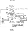
- Fig. 18 is a flowchart for explaining an example of
the operation of the failure detecting system for a shift
range switch signal line according to Fig. 1;
- Fig. 19 is a flow chart for explaining an example of
the operation of the failure detecting system for a shift
range switch signal line according to Fig. 1.
-
DETAILED DESCRIPTION OF THE INVENTION
-
The embodiment of the present invention will be
explained with reference to accompanying drawings.
-
Fig. 1 shows a control system according to an
embodiment of a failure detecting system for an automatic
transmission of a vehicle of the present invention. The
control system employs an engine rotational speed as one of
input signals to control the automatic transmission. A
failure is detected on the engine rotational speed when
conditions to be described later are satisfied. When the
failure is detected, a transmission control based on the
engine rotational speed is prohibited, and a state before
the failure is detected is maintained. The controls based
on the engine rotational speed includes, for example, a
gear shift control, a lockup control, and a line pressure
control.
-
A throttle opening detection signal from a throttle
sensor 11 and an ATF oil temperature detection signal from
an ATF temperature sensor 12 are input to an input
interface circuit 21 of an electronic control unit (ECU) 20
of the control system. The throttle opening detection
signal from the throttle sensor 11 is used to determine a
gear shifting point, a line pressure in a control circuit
of the automatic transmission and a lockup vehicle speed
for the lockup. The ATF oil temperature detection signal
from the ATF temperature sensor 12 is used to prohibit
lockup at the time of a low temperature and to release a
fourth gear.
-
Various detection signals input through the input
interface circuit 21 are converted to digital signals
through an A/D converter 22, and then fed to a CPU 24. A
program for executing a predetermined calculation of the
CPU 24 is stored in a memory 24a associated with the CPU
24.
-
A vehicle speed detection signal from a vehicle speed
sensor 13, an engine rotational speed detection signal from
an ignition pulse generator 14, a shift range signal
from an inhibitor switch 14, and a throttle full close
state detection signal from an idle switch 16, an ABS
signal from an ABS control unit 19a, a cruise control
signal from a cruise control unit, and a brake switch
signal from a brake switch 19 are input to an input
interface circuit 23. The vehicle speed detection
signal from the vehicle speed sensor 13 is used to control
a gear shifting, lockup, line pressure and transfer. The
engine rotational speed detection signal from the ignition
pulse generator 14 is used to smoothly control the lockup
operation and to prevent overrunning of an engine in a "1",
"2" or "3" range. The shift range signal from the
inhibitor switch 15 is used to determine the line pressure.
The throttle full close state detection signal from the
idle switch 16 is used to release a lockup clutch and to
control the line pressure.
-
An output of the CPU 24 is applied to an output
interface circuit 25 for controlling ON/OFF of shift
solenoids (1)31, (2)32, (3)33 and an output interface
circuit 26 for controlling duty ratios of duty solenoids
(A)34, (B)35 and (C)36.
-
The shift solenoids (1)31, (2)32 control gear
shifting, especially, its timing, thereby reducing a gear
shifting shock. The shift solenoid (3)33 controls an
overrunning clutch and a timing of shifting from a third
gear to a second gear. The timing control reduces a shock
at the time of shifting down the speed, and the overrunning
clutch is operated at the time of decelerating, thereby
effecting an engine brake.
-
The duty solenoid (A)24 regulates the line pressure to
an optimum pressure responsive to a driving state. The
duty solenoid (B)35 smoothly engages or disengages the
lockup clutch. The duty solenoid (C) 36 regulates a
hydraulic oil pressure of a transfer clutch to control the
rear wheel drive force.
-
The operation of the automatic transmission control
system described above will be explained by referring to
Fig. 2.
-
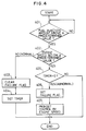
Fig. 2 shows a flow in case that an amount of
engine intake air is used to detect a failure of the engine
rotational speed detection signal. When an air amount
detection signal from an air flow sensor 17 is input to the
CPU 24 of the ECU 20, whether or not an amount of intake
air is larger than a predetermined value is judged (in a
step 201). When it is judged that the amount of induction
air is larger than a predetermined value, whether or not an
engine rotational speed based on the engine rotational
detection signal from the ignition pulse generator 14 is
smaller than a predetermined value is judged (in a step
202). If it is judged that the engine speed is not smaller
than a predetermined value, it is normal. A failure flag
set, for example, to a register (not shown) provided in the
CPU 24 is cleared, and a timer (not shown) in the CPU 24 is
set to a predetermined time (in steps 203 and 204).
-
Moreover, when it is judged that the engine rotational
speed is smaller than the predetermined value (in the step
202) and a state that the engine rotational speed is
smaller than the predetermined value continues for more
than the predetermined time is further judged (in a step
205), a failure flag is set to the register (not shown) (in
a step 206). Thus, the failure flag is set to prohibit an
automatic transmission control based on the engine
rotational speed (in a step 207), and it is controlled to
maintain the previous state before the engine rotational
signal failure is judged.
-
On the contrary, if the state that the engine
rotational speed is smaller than the predetermined value
continues for more than the predetermined time is not
judged (in the step 205), a failure is not detected, and
the automatic transmission based on the engine rotational
speed is continued.
-
Fig. 4 shows a flow in case where the amount of
intake air of a decision condition is replaced with a fuel
injection amount. First, whether or not the fuel injection
amount is larger than a predetermined value is judged (in a
step 401). When the predetermined value of the fuel
injection amount is calculated based on the intake air
amount detection signal from the air flow sensor 17, and
compared with an actual injection pulse width to the
injection, thereby judging the fuel injection amount.
-
In case where it is judged that the fuel injection
amount is larger than the predetermined value, it is judged
that the engine rotational speed indicated by the engine
rotational detection signal from the ignition pulse 14 is
smaller than a predetermined value (in a step 402). If it
is judged that the engine rotational speed is not smaller
than the predetermined value, it is normal, a failure flag
set, for example, to a register (not shown) provided in the
CPU 24 is cleared and a timer (not shown) in the CPU 24 is
set to a predetermined time (in steps 403 and 404).
-
Moreover, when it is judged that the engine rotational
speed is smaller than the predetermined value (in the step
402) and a state that the engine rotational speed is
smaller than the predetermined value for more than a
predetermined time (in a step 405), a failure flat is set
to the register (not shown) (in a step 406). Thus, the
failure flag is set to prohibit the automatic transmission
control based on the engine rotational speed (in a step
407), and the state before the engine rotational speed
failure is detected is maintained to be controlled.
-
On the contrary, in case where the state that the
engine rotational speed is smaller than a predetermined
value is not continued for the predetermined time (in the
step 405), it is not decided to be failure, and the
automatic transmission control based on the engine
rotational speed is continued.
-
In the embodiment described above, the case where the
amount of intake air and the fuel injection amount are
larger than predetermined values is employed as one factor
of the decision condition. However, the present invention
is not limited to the particular embodiment. For example,
as shown in Figs. 3 and 5, a vehicle speed detected by the
vehicle speed sensor 13 may be added to the decision
condition.
-
More specifically, summary of flows of the case where
the above-described factors are employed as decision
conditions is as follows.
- (1) When the amount of engine intake air is larger than a
predetermined value, the state that the engine rotational
speed is smaller than a predetermined value is continued
for a predetermined time.
- (2) When the vehicle speed is larger than a predetermined
value, the amount of intake air is larger than a
predetermined value and the state that the engine
rotational speed is smaller than a predetermined state
is continued for a predetermined time.
- (3) When the fuel injection amount is larger than a
predetermined value, the state that the engine
rotational speed is smaller than a predetermined value
is continued for a predetermined time.
- (4) When the vehicle speed is larger than a predetermined
value, the fuel injection amount is larger than a
predetermined value and the state that the engine
rotational speed is smaller than a predetermined value is
continued for a predetermined time.
-
-
In case where any of the above conditions (1) to (4)
is satisfied, it is determined that a failure occurs on the
engine rotational speed signal, the automatic transmission
control based on the engine rotational speed is prohibited,
and the state before the failure of the engine rotational
speed signal is detected is maintained.
-
In the embodiment described above, in case where the
amount of intake air or the fuel injection amount is larger
than predetermined value, when the engine rotational speed
detection signal from the ignition pulse generator 14 is
not suitably detected, a failure is determined, and the
automatic transmission control is executed in the state
before the failure is determined. Therefore, since the
failure of the engine rotational speed signal can be
reliably detected, the automatic transmission control based
on the engine rotational speed such as, for example, a
speed shift control, a lockup control, a line pressure
control can be appropriately controlled.
-
Another embodiment of the present invention will be
explained in detail with reference to Figs. 6 to 9.
-
Referring back to Fig. 1, showing a control system
including a failure detecting system for a cruise control
set signal line connected to an automatic transmission of a
vehicle. The control system employs a cruise control
signal from a cruise control unit as one of input signals
to control the automatic transmission. A failure on the
cruise control set signal line is determined when
conditions to be described later are satisfied. When the
failure is detected, a transmission control based on a
cruise control signal is prohibited. However, a normal
state is recovered when an OFF signal of the cruise control
is detected in the conditions to be described later.
-
As the automatic transmission control in case where
the cruise control signal from the cruise control unit is
employed, there are a gear shifting control (control at the
time of cruise control), a lockup control (ordinarily a
lockup control), an overrunning clutch control (namely,
engine brake control), etc.
-
The operation of the failure detecting system for the
cruise control set signal line connected to the automatic
transmission control system described above will be
explained by referring to Figs. 6 to 9.
-
Fig. 6 shows a flow to determine a case where a cruise
control signal is erroneously turned on at a vehicle speed
or less when the cruise control is not operated. When a
detection signal from, the vehicle speed sensor 13 is input
to the CPU 24 through an input interface circuit 23,
whether or not it is smaller than a predetermined value is
judged (in a step 601). In case where it is judged that
the detection signal is not smaller than the predetermined
value, a failure flag of the cruise control signal is
cleared, and a timer is set to a predetermined time (in
steps 602 and 603).
-
On the contrary, in case where it is judged that the
detection signal is smaller than the predetermined value,
whether or not the cruise control signal is input is judged
(in a step 604). In case where it is judged that the
cruise control signal is input, a failure flag of the
cruise control signal is set thereby to decide a failure
(in a step 605).
-
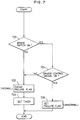
Fig. 7 shows a flow to determine a case where a cruise
control signal which ought to be released when a brake
switch is turned on is erroneously turned on. Whether or
not the brake switch 19 is turned on is judged (in a step
701). In case where a brake ON signal from the brake
switch 19 is not input, a failure flag of the cruise
control signal is cleared, and a timer is set to a
predetermined time (steps 702 and 703).
-
Moreover, in case where the brake ON signal from the
brake switch 19 is input, it is judged whether or not the
cruise control signal is input is judged (in a step 704),
while when it is judged that the cruise control signal is
input, a failure flag of the cruise control signal is set
to decide a failure (in a step 705).
-
Fig. 8 shows a flow to determined a case where a
cruise control signal is erroneously turned on in an "N" or
"P" range. A neutral range (N) or a parking range "P" is
judged based on a shift range signal from the inhibitor
switch 15 (in a step 801). As a result of the judgement,
in case it is judged that the shift range signal does not
indicate the neutral range (N) nor the parking range (P), a
failure flag of the cruise control signal is cleared, and a
timer is set to a predetermined time (in steps 802 and
803).
-
On the contrary, in case where the neutral range (N)
or the parking range (P) is detected in the step 801,
whether the cruise control signal is input or not is judged
(in a step 804). In case where the cruise control signal
is input, a failure flag of the cruise control signal is
set to judge the failure (in a step 805).
-
Fig. 9 shows a flow to determine a case where any of
when the cruise control signal is erroneously turned on at
a vehicle speed or less in the case of cruise control
non-operation, when the cruise control signal which ought
to be released at the time of turning the brake switch on
is erroneously turned on, and when the cruise control
signal is erroneously turned on in an "N" or "P" range is
continued for a predetermined time. First, when a
detection signal from the vehicle speed sensor 13 is input
to the CPU 24 through the input interface circuit 23, it is
judged that the detection signal is smaller than a
predetermined value or not (in the step 901). In case
where the signal is judged not to be smaller than the
predetermined value, whether or not the brake switch 19 is
turned on is judge (in the step 902). In case where a
brake ON signal from the brake switch 19 is not input, the
neutral range (N) or the parking range (P) is judged based
on a shift range signal from the inhibitor switch 15 (in
the step 903).
-
As a result of the judgement, in case where the signal
is judged not to be the neutral range "N" nor the parking
range "P", a failure flag of the cruise control signal is
cleared, and a timer is set to a predetermined time (in
steps 904 and 905).
-
Moreover, when the vehicle speed is not smaller than
the predetermined value (in the step 901), when the brake
ON signal is detected (in the step 902), or further when
either of the neutral range (N) and the parking range (P)
is detected (in the step 903), whether or not the cruise
control signal is input is judged (in a step 906). If the
cruise control signal is not input, the flow is advanced to
the step 904, and the failure flag is cleared. However, in
case where the cruise control signal is not input, whether
the timer becomes "zero" or not is judged (in a step 907).
That is, the "zero" of the timer means that the
predetermined time is elapsed. In case where the timer
becomes "zero", the failure flag of the cruise control
signal is set to decide the failure (in a step 908).
-
Summary of the conditions for detecting the failure of
the cruise control set signal line is as follows.
- (1) When the cruise control is not operated, the cruise
control signal is erroneously turned on
in case where a vehicle speed is smaller than a
predetermined value.
- (2) When a brake switch is turned on, the cruise control
signal which ought to be released is erroneously turned
on.
- (3) When an "N" or "P" range, the cruise control signal is
erroneously turned on.
- (4) Any of the conditions (1) to (3) is continued for a
predetermined time.
-
-
In case where any of the above conditions (1) to (4)
is satisfied, a failure on the cruise control set signal
line is detected, the automatic transmission control based
on the cruise control signal is prohibited.
-
In the embodiment described above, a normal state is
recovered when an OFF signal of the cruise control is
detected after one of the above-described conditions is
satisfied.
-
Accordingly, since a failure of the cruise control set
signal line is reliably detected, the automatic
transmission control using the cruise control signal is
appropriately executed.
-
Still another embodiment of the present invention will
be explained in detail with reference to Figs. 10 to 14.
-
Referring back to Fig. 1, showing a control system
including a failure detecting system for a brake switch
connected to an automatic transmission of a vehicle. The
control system employs a brake signal from the brake switch
as one of input signals to control the automatic
transmission. A failure of the brake switch is detected
when conditions to be described later are satisfied. When
the failure is detected, a transmission control based on
the brake signal is prohibited. However, a normal state is
recovered when an OFF signal of the cruise control is
detected after one of the conditions to be described later
is satisfied. Control for a four-wheel drive transfer
clutch in the automatic transmission (control at the time
of operating ABS) is performed in response to the brake
signal.
-
The operation of the failure detecting system for the
brake switch connected to the automatic transmission
control system described above will be explained by
referring to Figs. 10 - 12.
-
Fig. 10 shows a flow to determined a case where a
brake on signal is not detected which the vehicle speed is
decelerated until a vehicle is stopped, and when this
phenomenon is continuously repeated predetermined times.
-
More specifically, when a detection signal from the
vehicle speed sensor 13 is input to the CPU 24 through an
input interface circuit 23, the vehicle speed is judged (in
a step 1001). When the vehicle speed is, for example,
faster than 30km/hr, a check flag is set (in a step 1002).
-
On the contrary, in case where the vehicle speed is
slower than 30km/hr, presence/absence of the check flag is
judged (in a step 1003). If the check flag is not set, the
check flag is reset. In case where the check flag is set,
ON/OFF of the brake switch 19 is judged (in a step 1004).
If the brake switch 19 is judged to be turned on, the check
flag is cleared, and a counter is also cleared (in a step
1005).
-
In case where the brake switch 19 is turned off,
whether or not the vehicle speed becomes "zero" is judged
(in a step 1006). If it is judged that the vehicle speed
becomes "zero", the check flag is cleared, and a counter is
counted up (in a step 1007). In case where a counted-up
value reaches a predetermined value N by repeating the
count-up of the counter (in a step 1008), an error flag is
set, and the automatic transmission at the time of brake is
prohibited (in steps 1009 and 1010).
-
Fig. 11 shows a flow to determine a case where the
brake ON signal is not detected when a deceleration of the
vehicle is larger than a predetermined value, and when this
phenomena occurs continuously predetermined times.
-
More specifically, whether the deceleration of the
vehicle is larger than the predetermined value or not is
judged (in a step 1101). In case where it is judged that
the deceleration is larger than the predetermined value,
presence/absence of the brake ON signal is judged (in a
step 1102). If the brake ON signal is detected, a counter
is cleared (in a step 1103).
-
In case where the brake ON signal is not detected, the
counter is counted up in a step 1104. When the counted-up
value reaches a predetermined times, an error flag is set,
and the automatic transmission control at the time of the
brake is prohibited (in steps 1105 to 1107).
-
Fig. 12 shows a flow combining both two cases
described above. Whether the vehicle speed is faster than
a predetermined value or not is judged prior to the
decision of the deceleration shown in Fig. 11 (in a step
1201).
-
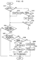
Fig. 13 shows a flow to determine a case where absence
of the brake ON signal is detected, predetermined times
when the P or R range is selected in the vehicle having a
shift locking mechanism.
-
More specifically, when a shift range signal from the
inhibitor switch 15 is input to the CPU 24 through the
input interface circuit 23, a range position is judged (in
a step 1301). In case where the range is altered from the
P range to the R range, whether or not the brake switch 19
is turned on is judged (in a step 1302). That is, in this
case, it is premise that the shift locking mechanism
between the P and R ranges is provided, which is released
by manipulating a shift lever with the depression of a
brake pedal.
-
In case where the brake ON signal is detected, stored
information in a RAM(A) (not shown) of a memory 24a
associated with the CPU 24 is cleared (in a step 2303).
Moreover, in case where the brake ON signal is not
detected, the number of counts stored in RAM(A), indicating
the number of detections of the brake ON signal is added
(in a step 1304). When the added number in the RAM(A)
reaches a predetermined value N, a brake failure flag is
set, and hence an automatic transmission control in
response to the brake switch is prohibited (in a step
1313).
-
Furthermore, in case where the added number in the
RAM(A) (in a step 1305) does not reach the predetermined
value N, the vehicle speed is judged (in a step 1306).
That is, when a detection signal from the vehicle speed
sensor 13 is input to the CPU 24 through an input interface
circuit 23, a predetermined speed is compared with a
detected speed from the vehicle speed sensor 13, and
whether the detected speed is faster than the predetermined
speed or not can be judged. In case where it is judged
that the detected speed is larger than the predetermined
speed, ON/OFF of the brake switch 19 is judged (in a step
1308). In case where the brake ON signal is detected,
stored information in a RAM(B) (not shown) of the memory
24a is cleared, and further a brake failure flag is cleared
(in steps 1309 and 1310).
-
On the contrary, in case where the brake ON signal is
not detected, the number of counts stored in RAM(B)
indicating the number of detections of the brake ON signal
is added to the RAM(B) (in a step 1311). When the added
number in the RAM(B) reaches a predetermined value N, the
brake failure flag is set, and hence the automatic
transmission control in response to the brake switch is
prohibited (in a step 1313).
-
More specifically, summary of the flow detecting a
failure of the brake signal is as follows.
- (1) When the vehicle speed is decelerated until a vehicle
is stopped, a brake ON signal is not detected, and when
this phenomenon occurs continuously predetermined times.
- (2) When a deceleration of the vehicle is larger than
a predetermined value, the brake ON signal is not
detected, and when this phenomenon occurs continuously
predetermined times.
- (3) In case where the vehicle speed is larger than a
certain value, and the condition (2) is satisfied,
- (4) In a vehicle having a shift locking mechanism, when a R
range is selected from a P range, absence of the
brake ON signal continuously occurs predetermined times.
-
-
In case where any of the above conditions (1) to (4)
is satisfied, a failure of the brake signal is detected,
the automatic transmission control using the brake signal
is prohibited. However, a normal state is recovered when
the brake signal is detected after one of the
above-described conditions is satisfied.
-
Therefore, since the check switch for instructing
a check before the cruise control like prior art is
eliminated, its structure is not only simplified, but also
a failure of the brake switch in the various running states
is reliably detected, and hence the automatic transmission
control using the brake signal is appropriately executed.
-
Still another embodiment of the present invention will
be explained in detail with reference to Figs. 16 to 19.
-
Referring back to Fig. 1, showing a control system
including a failure detecting system for a shift range
(inhibitor) switch signal used for an automatic
transmission control. The control system employs a shift
range signal from an inhibitor switch as one of control
signals to control the automatic transmission. A failure
is detected when conditions of the range signal to be
described later are satisfied. When the failure is
detected, a transmission control based on the range signal
is prohibited.
-
The operation of the failure detecting system for the
shift range switch signal of the automatic transmission
control system described above will be explained by
referring to Fig. 16.
-
First, whether the vehicle speed V is higher than a
predetermined value Vo or not is judged (in a step 1601).
When the vehicle speed is higher than the predetermined
value, the shift range signal from the inhibitor switch 15
is fetched to the CPU 24 through the input interface
circuit 23 (in a step 1602).
-
Then, whether the shift range signal is input or not
is judged (in a step 1603). In case where no input is
judged, whether the range detected in previous routine is
the "N" range or not is judged in next step (in a step
1604). In case where the "N" range is judged, i.e., when
no shift range signal has been input after the "N" range,
lapse of a time counted by a timer is judged (in a step
1605). In case where it is judged that a predetermined
time is elapsed after the step 1604 is affirmed, a failure
flag is set (in a step 1606), the present range is regarded
as being the "D" range, and an automatic transmission
control for the "D" range is executed (in step 1607).
-
On the other hand, in case where it is judged that the
shift range signal is present in the step 1603, the timer
is set to To (in a step 1608), and the input shift range
signal is stored as a present range (in a step 1609).
-
In case where the predetermined time is not elapsed in
the step 1605, the timer is counted down (in a step 1610).
-
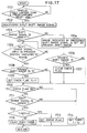
Fig. 17 shows a flow of detecting a failure when a
certain range is overlooked.
-
First, whether the vehicle speed is a predetermined
value Vo or more is judged (in a step 1701). When the
vehicle speed is higher than the predetermined value, a
shift range signal from the inhibitor switch 15 is fetched
to the CPU 24 through the input interface circuit 23 (in a
step 1702).
-
Then, whether the shift range signal is input or not
is judged (in a step 1703). In case where it is judged
that the shift range signal is input, the input signal
range is recognized as being the present range (in a step
1704). In case where it is judged that the shift range
signal is not input, whether the range detected in previous
routine is the "N" range or not is judged (in a step 1705).
In case where the "N" range is judged, a check flag is set
(in a step 1706). In case where the range in previous
routine is not the "N" range, whether the present shift
range is "D" range is judged (in the step 1706). When "D"
range is judged, the check flag is cleared (in a step
1707).
-
In case where the range detected in previous routine
is "N" range, whether the present range is a "3" range or
not is judged (in a step 1708).
-
In case where the present range is judged to be the
"3" range, a check flag F1 is set (in a step 1709). This
check flag is set only when the "3" range is detected
without the detection of "D" range immediately after the
"N" range. In a step 1710, the check flag F1 is judged.
When the check flag is set, whether the range signal is
input or not is judged (in a step 1711). In case where it
is judged that the range signal is absent, whether the
timer is "0" or not is judged. In case where a
predetermined time To is not elapsed, the timer is counted
down (in steps 1712 and 1715). In case where it is judged
that the timer is "0", an error flag is set to indicate a
failure of the shift range signal (in a step 1713).
-
In case that the check flag F1 is not set or the shift
range signal is present, the timer is set to the
predetermined time To (in a step 1714).
-
To summarize of the respective flows in Figs. 16 and
17, the conditions for detecting the failure of the shift
range switch is as follows.
- (1) No input state is continued for a predetermined time
after the "N" range is detected when the vehicle is
traveled at a predetermined vehicle speed or higher.
- (2) No input state is continued for a predetermined time
after the certain range such as the "3" range is detected
in case where such the certain range is detected over the
"D" range after the "N" range is detected without the
detection of the "D" range after the "N" range is detected
when the vehicle is traveled at a predetermined vehicle
speed or higher.
-
-
In case where any one condition of the above
conditions (1) and (2) is satisfied, the gear shift control
is conducted. In the case of the above condition (1), it
is regarded as being the "D" range, the gear shift control
for the "D" range is conducted. In the case of the above
condition (2), a trouble is displayed, and the gear shift
control for such the certain range is maintained.
-
Therefore, since the failure of the shift range switch
is reliably detected by the foregoing logic, the automatic
gear shift control responsive to the shift range switch is
suitably conducted without necessity of new failure
detecting sensor.
-
Figs. 18 and 19 show still another example of the
condition to detect the failure of the shift range switch.
-
First, in case where a shift range signal from the
inhibitor switch 15 is not fetched to the CPU 24 through
the input interface circuit 23, the vehicle speed detection
signal indicative of the vehicle speed from the vehicle
speed sensor 13 and presence/absence of the shift range
signal are judged (in steps 1801 and 1802).
-
In case where the vehicle speed is the predetermined
vehicle speed or more and the input shift range signal is
present, the timer is set to a predetermined time To (in a
step 1805). Then, the input shift range signal is stored
as ROLD and the gear shift control for the shift range
indicated by the input shift range signal is performed (9n
a step 1806). In case where the shift range signal is not
present, lapse of the time counted by the timer is judged
(in a step 1803). In case where the predetermined time To
is not elapsed, the timer is counted down (in a step 1807).
In case where the predetermined time To is elapsed, the
shift range operated before the shift range signal becomes
absent is maintained (in a step 1804).
-
In Fig. 19, in case where the "P" or "N" range is not
recognized from the shift range signal from the inhibitor
switch 15 when the starter switch is closed, the previous
shift range is maintained (in steps 1901, 1902 and 1903).
-
On the other hand, when the starter switch is not
closed in the step 1901, whether the vehicle speed is
faster than the predetermined vehicle speed or not is
judged. In case where the vehicle speed is faster than the
predetermined vehicle speed, the present input of the shift
range signal is judged (in steps 1904 and 1905). In case
where it is judged that the shift range signal is not input
at present, lapse of the time is judged (in a step 1906).
In case where the predetermined time is elapsed after the
step 1905 is affirmed, the shift range operated before the
shift range signal becomes absent (in a step 1903).
-
To summarize the flows in Figs. 18 and 19, the
conditions for detecting the failure of the shift range
switch is as below.
- (3) No input state of the shift range at a predetermined
vehicle speed or higher is elapsed for a predetermined
time.
- (4) P or N range is not recognized when the starter switch
is closed.
-
-
In case where any one of the above conditions (3) and
(4) is satisfied, the shift range used before the failure
occurs is subsequently maintained, and the automatic gear
shift control for such the maintained shift range is
suitably conducted.
-
While the presently preferred embodiments of the
present invention have been shown and described, it is to
be understood that these disclosures are for the purpose of
illustration and that various changes and modifications may
be made without departing from the scope of the invention
as set forth in the appended claims.