EP0937184B1 - Plancheiage en carreaux - Google Patents
Plancheiage en carreaux Download PDFInfo
- Publication number
- EP0937184B1 EP0937184B1 EP97948841A EP97948841A EP0937184B1 EP 0937184 B1 EP0937184 B1 EP 0937184B1 EP 97948841 A EP97948841 A EP 97948841A EP 97948841 A EP97948841 A EP 97948841A EP 0937184 B1 EP0937184 B1 EP 0937184B1
- Authority
- EP
- European Patent Office
- Prior art keywords
- plate
- shaped
- tiles
- flooring according
- shaped support
- Prior art date
- Legal status (The legal status is an assumption and is not a legal conclusion. Google has not performed a legal analysis and makes no representation as to the accuracy of the status listed.)
- Expired - Lifetime
Links
Images


Classifications
-
- E—FIXED CONSTRUCTIONS
- E04—BUILDING
- E04F—FINISHING WORK ON BUILDINGS, e.g. STAIRS, FLOORS
- E04F15/00—Flooring
- E04F15/02—Flooring or floor layers composed of a number of similar elements
- E04F15/024—Sectional false floors, e.g. computer floors
- E04F15/02405—Floor panels
- E04F15/02411—Floor panels with integrated feet
-
- E—FIXED CONSTRUCTIONS
- E04—BUILDING
- E04F—FINISHING WORK ON BUILDINGS, e.g. STAIRS, FLOORS
- E04F15/00—Flooring
- E04F15/02—Flooring or floor layers composed of a number of similar elements
- E04F15/024—Sectional false floors, e.g. computer floors
-
- E—FIXED CONSTRUCTIONS
- E04—BUILDING
- E04F—FINISHING WORK ON BUILDINGS, e.g. STAIRS, FLOORS
- E04F15/00—Flooring
- E04F15/02—Flooring or floor layers composed of a number of similar elements
- E04F15/024—Sectional false floors, e.g. computer floors
- E04F15/02447—Supporting structures
- E04F15/02464—Height adjustable elements for supporting the panels or a panel-supporting framework
- E04F15/0247—Screw jacks
Definitions
- the present invention relates in general terms to a flooring and more specifically to a flooring according to the preamble of claim 1, as disclosed in US-A-4 736 555.
- the flooring thus obtained, which is advantageous from various points of view, has a disadvantage, however, which is revealed when it has to be removed in part, for example in order to gain access to cables, pipes and the like, which were laid at the same time as the flooring, or in order to lay these subsequently.
- the disadvantage is that removal of the tiles is laborious and inevitably involves the destruction of many if not all the tiles to be removed, with the consequent necessity of replacing them.
- the problem underlying the present invention is to devise a flooring of the type indicated, which has structural and functional characteristics which make it possible to overcome the abovementioned disadvantage, is more robust and has an improved capacity for deadening impacts, vibrations and noise.
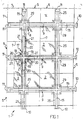
- reference number 1 generally indicates a flooring according to the present invention.
- the flooring 1 comprises a plurality of tiles, all indicated by 2, which are square in the example and arranged regularly essentially side by side in rows at right angles. Each tile 2 has four corners 3 and four sides 4.
- the flooring 1 also comprises a plurality of plate-shaped supports, all indicated by 5, which are square in the example.
- Each plate-shaped support 5 has a centre 6 and four sides 7.
- the plate-shaped supports 5 are arranged below the tiles 2 in a regular manner and essentially quincuncially in relation to the plurality of tiles in such a manner that the centre 6 of each plate-shaped support 5 is situated below the corners 3 of four adjacent tiles 2.
- the plate-shaped supports are made by moulding an appropriate elastomer, for example rubber.
- Fixing means 8 which will be described below, are provided for fixing the tiles 2 to the plate-shaped supports 5 in a removable manner.
- the plate-shaped supports 5 are side by side in mutual contact side to side.
- a joint 9 is provided, which stably retains the adjacent plate-shaped supports in relation to one another.
- the joint 9 comprises a hammer-shaped projection 10, which is formed halfway along a side 7 of a plate-shaped support, and a hammer-shaped recess 11 which mates with the projection 10 and is formed halfway along a side 7 of the adjacent plate-shaped support.
- Each plate-shaped support 5 has projections and recesses in equal number, and specifically two projections and two recesses, one on each side, so that all the plate-shaped supports are identical with one another.
- each plate-shaped support 5 On its lower surface 5a, each plate-shaped support 5 has a plurality of channels 12 distributed in two groups of channels which are parallel to the sides and intersect one another at right angles and are advantageously dimensioned for the passage of cables, pipes and the like, which are indicated diagrammatically by 13.
- each plate-shaped support On its upper surface 5b, each plate-shaped support has a raised portion 14 shaped like a Greek cross with arms 15 converging into the centre 6 which have an essentially rectangular section.
- the raised portion 14 constitutes a filler or a bead between adjacent tiles.
- each plate-shaped support is preferably in mutual contact with the raised portions of the adjacent plate-shaped supports. That is to say the arms 15 have free ends 16, opposite the centre 6, which touch with their tip the free ends of the arms of the adjacent plate-shaped support.
- a covering generally indicated by 17 is fitted onto the raised portion 14.
- Reference number 21 indicates feet which project in a cantilevered manner from the arms and from the strips; rest on the plate-shaped support and are surmounted by the tiles.
- the tiles 2 have a reinforcing core 22 which takes the form of a plate made of a ferrous material, for example common steel, and have on an upper surface 2a a covering 23 which takes the form of a sheet of a valuable material, for example a sheet of stainless steel, turned down over the reinforcing core, forming an edge 24 which surrounds the reinforcing core along its periphery on a lower face 2b of the tile.
- a reinforcing core 22 which takes the form of a plate made of a ferrous material, for example common steel, and have on an upper surface 2a covering 23 which takes the form of a sheet of a valuable material, for example a sheet of stainless steel, turned down over the reinforcing core, forming an edge 24 which surrounds the reinforcing core along its periphery on a lower face 2b of the tile.
- the tile 2 rests with its lower surface 2b on the upper face 5b of four adjacent plate-shaped supports 5 which are situated below the tile 2.
- the edge 24 rests in a rabbet 25 formed in the plate-shaped supports along the arms 15 of the raised portions.
- the fixing means 8 comprise a screw 26 which extends between each corner 3 of the four corners of respective adjacent tiles 2, which are situated above a plate-shaped support, and the plate-shaped support itself, said screw extending through holes 26a and 26b formed in the tile and in the plate-shaped support respectively.
- the fixing means 8 preferably comprise a metal insert 27 which is associated with the plate-shaped support and is equipped with a thread 28 engaged in a screwing manner by the screw 26.
- the inserts 27, in which the screws 26 of the four corners are in screwing engagement constitute a single piece in the form of a square metal plate 29 accommodated in a recess 30 formed in the lower face 5a of the plate-shaped support.
- the flooring 1 comprises fixing means 31 formed by a press-button 32 which extends between each corner of the four corners of adjacent tiles which are situated above a plate-shaped support.
- the press-button comprises a mushroom-shaped element 33, which projects from a base 34 associated with the plate-shaped support, and a seat 35 formed in the tile.
- the bases of each plate-shaped support constitute a single piece in the form of a square metal plate 36 accommodated in a recess 37 formed in the plate-shaped support.
- the flooring 1 comprises tiles 41, each of which comprises a reinforcing core 42 and, on the opposite faces 41a and 41b, a first covering 43 and a second covering 44 respectively.
- the first covering 43 takes the form of a sheet of stainless steel while a material with low thermal conductivity is selected for the second covering.
- the second covering is a sheet of valuable wood.
- Each tile 41 is provided with screw fixing means and can be fixed to the plate-shaped supports by one or the other of the two faces 41a and 41b alternatively.
- the main advantage of the flooring according to the present invention lies in the fact that it lends itself to being rapidly removed locally as required and to being completely'reinstated again using the same tiles which have been removed any number of times so as always to assume the identical appearance again.
- a further advantage of the flooring according to the present invention lies in the fact that it can be laid rapidly.
- a further advantage lies in the fact that it has great resistance to penetration of water, during cleaning, thanks to the presence of the cross-like raised portions provided in the plate-shaped supports.
- a further advantage of the flooring according to the invention rests in the fact that it lends itself to being made so as to achieve an aesthetic quality also thanks to appropriate selection of materials for the tiles and the coverings of the raised portions.
- the flooring according to the invention also lends itself to being adapted to different climatic conditions, for example to winter and to summer, by laying the tiles with whichever of the two coverings is indicated from case to case.
- the flooring according to the invention is also structurally simple and robust which is an advantage in particular for a manufacture which is intended to have a long service life.
- the fixing means not only secure the tiles firmly to the plate-shaped supports but also secure the tiles firmly in relation to one another by means of the plate-shaped supports, rendering the flooring a whole.
- the flooring according to the invention also lends itself to being made with tiles of various shapes.
Claims (17)
- Planchéiage comprenant une pluralité de carreaux (2), une pluralité de supports en forme de plaque (5) agencés en dessous des angles des carreaux adjacents et des moyens de fixation pour une fixation amovible des carreaux aux supports en forme de plaque, dans lequel les moyens de fixation comprennent des vis (8) et une pièce rapportée métallique (29), lesdites vis s'étendant à travers des trous formés respectivement dans chaque angle des carreaux (2) et dans le support en forme de plaque (5), ladite pièce rapportée métallique, distincte dudit support en forme de plaque et associée à la face inférieure du support en forme de plaque, étant équipée de trous filetés dans lesquels lesdites vis s'engagent, caractérisé en ce que les trous formés dans chaque support en forme de plaque se trouvent dans une région centrale de celui-ci, de sorte que lesdits supports en forme de plaque (5) peuvent être déplacés par rapport auxdits carreaux de sorte que chacun desdits supports en forme de plaque supporte un angle de quatre carreaux adjacents et dans lequel lesdits supports en forme de plaque ont des dimensions sensiblement égales aux dimensions des carreaux.
- Planchéiage comprenant une pluralité de carreaux (2), une pluralité de supports en forme de plaque (5) agencés en dessous des angles des carreaux adjacents et des moyens de fixation pour une fixation amovible des carreaux aux supports en forme de plaque, dans lequel les moyens de fixation comprennent des boutons-pressions et une base (34) associés au support en forme de plaque (5), chacun desdits boutons-pressions comprenant un élément en forme de champignon (33) faisant saillie depuis la base (34) et s'étendant par des trous formés dans le support en forme de plaque jusqu'à un siège formé dans chaque angle des angles des carreaux adjacents respectifs, caractérisé en ce que les trous formés dans chaque support en forme de plaque se trouvent dans une région centrale de celui-ci, de sorte que lesdits supports en forme de plaque peuvent être déplacés par rapport auxdits carreaux de sorte que chaque support en forme de plaque supporte un angle de quatre carreaux adjacents et dans lequel lesdits supports en forme de plaque ont des dimensions sensiblement égales aux dimensions des carreaux.
- Planchéiage selon la revendication 1 ou la revendication 2, caractérisé en ce que chaque support en forme de plaque comprend une partie surélevée constituant une cale entre les carreaux adjacents.
- Planchéiage selon la revendication 3, et dans lequel les carreaux sont carrés, caractérisé en ce que la partie surélevée a la forme d'une croix grecque.
- Planchéiage selon la revendication 4, caractérisé en ce que les supports en forme de plaque sont carrés et sont en contact mutuel.
- Planchéiage selon la revendication 5, caractérisé en ce que la partie surélevée de chaque support en forme de plaque est en contact mutuel avec les parties surélevées des supports en forme de plaque adjacents.
- Planchéiage selon la revendication 6, caractérisé en ce qu'il comprend un revêtement pour la partie surélevée en forme de croix grecque, formée par une croix ayant des bras courts et par des bandes s'étendant entre les bras des croix adjacentes.
- Planchéiage selon la revendication 7, caractérisé en ce que les bras et les bandes ont une section en forme de U retourné et sont équipés de pieds faisant saillie en porte à faux.
- Planchéiage selon la revendication 1 ou la revendication 2, caractérisé en ce qu'il comprend un joint entre les supports en forme de plaque adjacents.
- Planchéiage selon la revendication 9, caractérisé en ce que le joint comprend, formés respectivement sur les côtés opposés des supports en forme de plaque, une saillie en forme de marteau et un siège en forme de marteau qui s'accouple avec la saillie.
- Planchéiage selon la revendication 10, caractérisé en ce que chaque support en forme de plaque a des saillies et des cavités en nombre égal.
- Planchéiage selon la revendication 1 ou la revendication 2, caractérisé en ce que chaque support en forme de plaque comprend au moins un canal formé sur sa surface inférieure.
- Planchéiage selon la revendication 1 ou la revendication 2, caractérisé en ce que chaque carreau comprend un noyau de renforcement et un revêtement fait à partir d'un matériau de valeur qui a une bordure retournée au-dessus du noyau.
- Planchéiage selon la revendication 13, caractérisé en ce que chaque support en forme de plaque comprend une feuillure qui est dimensionnée pour s'adapter à ladite bordure du revêtement.
- Planchéiage selon la revendication 14, caractérisé en ce que le revêtement est une feuille d'acier inoxydable.
- Planchéiage selon la revendication 15, caractérisé en ce que le carreau comprend un second revêtement associé au noyau de renforcement sur la face opposée du revêtement en feuille d'acier inoxydable, un matériau à faible conductivité thermique étant choisi pour ledit second revêtement.
- Planchéiage selon la revendication 16, caractérisé en ce que le second revêtement est une feuille de bois.
Applications Claiming Priority (3)
| Application Number | Priority Date | Filing Date | Title |
|---|---|---|---|
| IT96MI002315A ITMI962315A1 (it) | 1996-11-07 | 1996-11-07 | Pavimento a piastrelle |
| ITMI962315 | 1996-11-07 | ||
| PCT/EP1997/006005 WO1998020212A1 (fr) | 1996-11-07 | 1997-10-30 | Plancheiage en carreaux |
Publications (2)
| Publication Number | Publication Date |
|---|---|
| EP0937184A1 EP0937184A1 (fr) | 1999-08-25 |
| EP0937184B1 true EP0937184B1 (fr) | 2004-01-21 |
Family
ID=11375170
Family Applications (1)
| Application Number | Title | Priority Date | Filing Date |
|---|---|---|---|
| EP97948841A Expired - Lifetime EP0937184B1 (fr) | 1996-11-07 | 1997-10-30 | Plancheiage en carreaux |
Country Status (9)
| Country | Link |
|---|---|
| US (1) | US6189289B1 (fr) |
| EP (1) | EP0937184B1 (fr) |
| JP (1) | JP3710827B2 (fr) |
| AT (1) | ATE258263T1 (fr) |
| AU (1) | AU7002598A (fr) |
| DE (1) | DE69727309T2 (fr) |
| HK (1) | HK1024515A1 (fr) |
| IT (1) | ITMI962315A1 (fr) |
| WO (1) | WO1998020212A1 (fr) |
Families Citing this family (35)
| Publication number | Priority date | Publication date | Assignee | Title |
|---|---|---|---|---|
| US6374563B1 (en) * | 1999-12-14 | 2002-04-23 | Mobil Oil Corporation | Anchoring system for ceramic lining tile |
| US6684592B2 (en) * | 2001-08-13 | 2004-02-03 | Ron Martin | Interlocking floor panels |
| US7140156B1 (en) * | 2002-09-25 | 2006-11-28 | Dlh Nordisk, Inc. | System for installation of decking tiles |
| US6865851B2 (en) * | 2003-05-14 | 2005-03-15 | The Wiremold Company | Modular floor panels with enclosed wireway channels |
| ITMI20040054A1 (it) * | 2004-01-16 | 2004-04-16 | E M Marketing S R L | Pavimento a piastrelle per l'ancoraggio di articoli di arredo |
| US7748177B2 (en) | 2004-02-25 | 2010-07-06 | Connor Sport Court International, Inc. | Modular tile with controlled deflection |
| CA2464062C (fr) * | 2004-04-13 | 2012-01-17 | Maxcess Technologies Inc. | Systeme de faux plancher modulaire avec joint etanche a l'air |
| US8407951B2 (en) * | 2004-10-06 | 2013-04-02 | Connor Sport Court International, Llc | Modular synthetic floor tile configured for enhanced performance |
| US8397466B2 (en) * | 2004-10-06 | 2013-03-19 | Connor Sport Court International, Llc | Tile with multiple-level surface |
| US7743568B1 (en) | 2005-02-25 | 2010-06-29 | Montgomery Mars | Tile system and method |
| US20070175132A1 (en) * | 2006-01-17 | 2007-08-02 | Daw Technologies, Inc. | Raised access floor |
| MX2008008889A (es) * | 2006-01-17 | 2008-09-12 | Lrm Ind Llc | Panel moldeado, sistema de panel moldeado y sistema de conexion. |
| US7832159B1 (en) * | 2006-06-06 | 2010-11-16 | Kayhart Paul H | Radiant in-floor heating system |
| RU2447248C2 (ru) * | 2006-11-20 | 2012-04-10 | Группо Конкорде С.П.А. | Способ сухой установки облицовочных плиток на полу или стенах и подложка, используемая при такой установке |
| GB2445740A (en) * | 2007-01-18 | 2008-07-23 | Intelligent Engineering | Flooring panels |
| US7984600B2 (en) | 2007-02-02 | 2011-07-26 | Mohawk Carpet Corporation | Groutless tile system and method for making the same |
| US8726612B2 (en) * | 2008-04-29 | 2014-05-20 | Steven G. Lomske | Modular panel |
| IT1394681B1 (it) | 2009-06-04 | 2012-07-13 | Gruppo Concorde Spa | Sistema di copertura modulare per superfici |
| EP2525881A4 (fr) * | 2010-01-22 | 2015-09-09 | Connor Sport Court International Inc | Système de sous-plancher modulaire |
| US8505256B2 (en) * | 2010-01-29 | 2013-08-13 | Connor Sport Court International, Llc | Synthetic floor tile having partially-compliant support structure |
| US8695288B2 (en) | 2011-04-26 | 2014-04-15 | United Construction Products, Inc. | Structural systems for restraining elevated surface tiles |
| US8387317B2 (en) * | 2011-04-26 | 2013-03-05 | United Construction Products, Inc. | Systems and support assemblies for restraining elevated deck components |
| JP5564480B2 (ja) * | 2011-09-26 | 2014-07-30 | 東芝Itサービス株式会社 | 床パネル及び床パネルを用いた床 |
| US8967904B1 (en) | 2012-10-05 | 2015-03-03 | Pioneer Detectable, LLC | Tactile plate assembly |
| US9038324B2 (en) | 2013-02-26 | 2015-05-26 | United Construction Products, Inc. | Field paver connector and restraining system |
| US11199007B2 (en) | 2013-10-25 | 2021-12-14 | Mbrico, Llc | Tile and support structure |
| CA2868866C (fr) | 2013-10-25 | 2021-10-26 | Mark A. Mcmanus | Carreau et structure de soutien |
| US11371245B2 (en) | 2013-10-25 | 2022-06-28 | Mbrico, Llc | Tile and support structure |
| US10041254B2 (en) | 2013-10-25 | 2018-08-07 | Mbrico, Llc | Tile and support structure |
| US10988931B1 (en) | 2013-10-25 | 2021-04-27 | Mbrico, Llc | Tile and support structure |
| JP6475004B2 (ja) * | 2014-08-01 | 2019-02-27 | センクシア株式会社 | フロアパネル |
| ITUA20164281A1 (it) * | 2016-06-10 | 2017-12-10 | Eps Italia Srl | Pannelli modulari per la realizzazione di una pavimentazione temporanea calpestabile componibile/scomponibile e metodo per realizzare detta pavimentazione |
| CA2975117C (fr) * | 2016-08-03 | 2020-02-11 | Kenneth Szekely | Coussin de palier |
| US10731350B1 (en) * | 2019-02-18 | 2020-08-04 | Yongzhi Yang | Paver lockdown systems against wind uplift that work with regular pedestals |
| US11428015B2 (en) | 2020-09-03 | 2022-08-30 | Wearwell, Llc | Modular platform system and method of assembly |
Citations (1)
| Publication number | Priority date | Publication date | Assignee | Title |
|---|---|---|---|---|
| US4736555A (en) * | 1985-05-22 | 1988-04-12 | Sekisui Kagaku Kogyo Kabushiki Kaisha | Free access type floor |
Family Cites Families (14)
| Publication number | Priority date | Publication date | Assignee | Title |
|---|---|---|---|---|
| US3025934A (en) * | 1958-01-30 | 1962-03-20 | Joseph W Spiselman | Sectional flooring |
| DE2225892A1 (de) * | 1972-05-27 | 1973-12-06 | Mengeringhausen Max | Vorgefertigter montagefussboden |
| US3899857A (en) * | 1973-12-12 | 1975-08-19 | Mitsuo Mochizuki | Framing element and its supporting device for laying interior boarding on foundation structure |
| US3927500A (en) * | 1974-09-16 | 1975-12-23 | Oscar M Plumlee | Fire resistant paneling system |
| US4085557A (en) * | 1976-06-01 | 1978-04-25 | James A. Tharp | Raised access floor system |
| US4277923A (en) * | 1979-10-18 | 1981-07-14 | Unistrut Corporation | Support pedestal assembly for a raised floor system |
| GB2130615A (en) * | 1982-11-23 | 1984-06-06 | Clifford Sidney Bundy | Floor panels |
| JPS6153958A (ja) * | 1984-08-20 | 1986-03-18 | 株式会社 サアミ | タイル状繊維床材敷設方法 |
| JP2506712B2 (ja) * | 1987-01-21 | 1996-06-12 | オ−エム機器株式会社 | フリ−アクセス床 |
| US4922670A (en) * | 1989-01-27 | 1990-05-08 | Naka Technical Laboratory | Free access floor and method of constructing the same |
| US5048242A (en) * | 1990-04-04 | 1991-09-17 | C-Tec, Inc. | Access floor system with hemmed edge panel |
| NL193196C (nl) | 1990-07-06 | 1999-02-02 | Vonderen Interior Contractors | Bouwelement voor een systeemvloer. |
| DE69106852T2 (de) * | 1990-11-29 | 1995-07-20 | Toshiba Kawasaki Kk | Verfahren zum Herstellen eines Systemfussbodens und Bodenstützfläche für Systemfussboden. |
| GB9123356D0 (en) * | 1991-11-02 | 1991-12-18 | Caveney Thomas M | Flooring |
-
1996
- 1996-11-07 IT IT96MI002315A patent/ITMI962315A1/it active IP Right Grant
-
1997
- 1997-10-30 AU AU70025/98A patent/AU7002598A/en not_active Abandoned
- 1997-10-30 WO PCT/EP1997/006005 patent/WO1998020212A1/fr active IP Right Grant
- 1997-10-30 AT AT97948841T patent/ATE258263T1/de not_active IP Right Cessation
- 1997-10-30 US US09/297,281 patent/US6189289B1/en not_active Expired - Fee Related
- 1997-10-30 DE DE1997627309 patent/DE69727309T2/de not_active Expired - Fee Related
- 1997-10-30 EP EP97948841A patent/EP0937184B1/fr not_active Expired - Lifetime
- 1997-10-30 JP JP52102698A patent/JP3710827B2/ja not_active Expired - Fee Related
-
2000
- 2000-02-25 HK HK00101163A patent/HK1024515A1/xx not_active IP Right Cessation
Patent Citations (1)
| Publication number | Priority date | Publication date | Assignee | Title |
|---|---|---|---|---|
| US4736555A (en) * | 1985-05-22 | 1988-04-12 | Sekisui Kagaku Kogyo Kabushiki Kaisha | Free access type floor |
Also Published As
| Publication number | Publication date |
|---|---|
| DE69727309T2 (de) | 2004-11-18 |
| ITMI962315A1 (it) | 1998-05-07 |
| HK1024515A1 (en) | 2000-10-13 |
| AU7002598A (en) | 1998-05-29 |
| EP0937184A1 (fr) | 1999-08-25 |
| ATE258263T1 (de) | 2004-02-15 |
| JP3710827B2 (ja) | 2005-10-26 |
| US6189289B1 (en) | 2001-02-20 |
| WO1998020212A1 (fr) | 1998-05-14 |
| DE69727309D1 (de) | 2004-02-26 |
| ITMI962315A0 (it) | 1996-11-07 |
| JP2001504177A (ja) | 2001-03-27 |
Similar Documents
| Publication | Publication Date | Title |
|---|---|---|
| EP0937184B1 (fr) | Plancheiage en carreaux | |
| EP1014846B1 (fr) | Tapis de sol | |
| US4287693A (en) | Interlocking rubber mat | |
| US6918215B2 (en) | Free floating sub-floor panel | |
| EP0191868B1 (fr) | Procede de pose de materiaux de couverture de sols en forme de tuiles | |
| CA2682033C (fr) | Support empilable pour porter des elements de plancher | |
| US5295341A (en) | Snap-together flooring system | |
| US5497590A (en) | Resilient flooring | |
| AU585021B2 (en) | Access floor construction | |
| US5647183A (en) | Resilient flooring | |
| WO1999036638A1 (fr) | Support de pavage ou de plancher | |
| US6158185A (en) | Resilient flooring | |
| US6079177A (en) | Removable ceiling panel assembly | |
| EP0256189B1 (fr) | Sols moléculaires | |
| US3082488A (en) | Floor or like tile | |
| DK0906994T4 (da) | Panel, især til gulvbelægning | |
| US20110203200A1 (en) | Deck system | |
| US7257929B2 (en) | Assembling module for floor or wall coverings | |
| US5058349A (en) | Surface tile for flooring and the like | |
| WO2000053865A1 (fr) | Systemes et procedes de pose de carrelage ceramique libre | |
| GB2348218A (en) | Height adjustable floor support | |
| JP3124951B2 (ja) | デッキパネル用足とそれを用いたデッキパネル | |
| GB2321070A (en) | Adustable support for flooring | |
| GB2356205A (en) | Resilient member with projections extending from at least one surface | |
| EP1309761B1 (fr) | Système de revêtement de sol avec un revêtement de sol et des panneaux de sous-plancher |
Legal Events
| Date | Code | Title | Description |
|---|---|---|---|
| PUAI | Public reference made under article 153(3) epc to a published international application that has entered the european phase |
Free format text: ORIGINAL CODE: 0009012 |
|
| 17P | Request for examination filed |
Effective date: 19990426 |
|
| AK | Designated contracting states |
Kind code of ref document: A1 Designated state(s): AT BE CH DE DK ES FI FR GB GR IE IT LI LU MC NL PT SE |
|
| AX | Request for extension of the european patent |
Free format text: AL PAYMENT 19990426;LT PAYMENT 19990426;LV PAYMENT 19990426;RO PAYMENT 19990426;SI PAYMENT 19990426 |
|
| 17Q | First examination report despatched |
Effective date: 20020103 |
|
| RAP1 | Party data changed (applicant data changed or rights of an application transferred) |
Owner name: E.M. MARKETINGS S.R.L. |
|
| GRAP | Despatch of communication of intention to grant a patent |
Free format text: ORIGINAL CODE: EPIDOSNIGR1 |
|
| GRAS | Grant fee paid |
Free format text: ORIGINAL CODE: EPIDOSNIGR3 |
|
| GRAA | (expected) grant |
Free format text: ORIGINAL CODE: 0009210 |
|
| AK | Designated contracting states |
Kind code of ref document: B1 Designated state(s): AT BE CH DE DK ES FI FR GB GR IE IT LI LU MC NL PT SE |
|
| AX | Request for extension of the european patent |
Extension state: AL LT LV RO SI |
|
| PG25 | Lapsed in a contracting state [announced via postgrant information from national office to epo] |
Ref country code: NL Free format text: LAPSE BECAUSE OF FAILURE TO SUBMIT A TRANSLATION OF THE DESCRIPTION OR TO PAY THE FEE WITHIN THE PRESCRIBED TIME-LIMIT Effective date: 20040121 Ref country code: LI Free format text: LAPSE BECAUSE OF FAILURE TO SUBMIT A TRANSLATION OF THE DESCRIPTION OR TO PAY THE FEE WITHIN THE PRESCRIBED TIME-LIMIT Effective date: 20040121 Ref country code: FR Free format text: LAPSE BECAUSE OF FAILURE TO SUBMIT A TRANSLATION OF THE DESCRIPTION OR TO PAY THE FEE WITHIN THE PRESCRIBED TIME-LIMIT Effective date: 20040121 Ref country code: FI Free format text: LAPSE BECAUSE OF FAILURE TO SUBMIT A TRANSLATION OF THE DESCRIPTION OR TO PAY THE FEE WITHIN THE PRESCRIBED TIME-LIMIT Effective date: 20040121 Ref country code: ES Free format text: LAPSE BECAUSE OF FAILURE TO SUBMIT A TRANSLATION OF THE DESCRIPTION OR TO PAY THE FEE WITHIN THE PRESCRIBED TIME-LIMIT Effective date: 20040121 Ref country code: CH Free format text: LAPSE BECAUSE OF FAILURE TO SUBMIT A TRANSLATION OF THE DESCRIPTION OR TO PAY THE FEE WITHIN THE PRESCRIBED TIME-LIMIT Effective date: 20040121 Ref country code: BE Free format text: LAPSE BECAUSE OF FAILURE TO SUBMIT A TRANSLATION OF THE DESCRIPTION OR TO PAY THE FEE WITHIN THE PRESCRIBED TIME-LIMIT Effective date: 20040121 Ref country code: AT Free format text: LAPSE BECAUSE OF FAILURE TO SUBMIT A TRANSLATION OF THE DESCRIPTION OR TO PAY THE FEE WITHIN THE PRESCRIBED TIME-LIMIT Effective date: 20040121 |
|
| REG | Reference to a national code |
Ref country code: GB Ref legal event code: FG4D |
|
| REG | Reference to a national code |
Ref country code: CH Ref legal event code: EP |
|
| REG | Reference to a national code |
Ref country code: IE Ref legal event code: FG4D |
|
| REF | Corresponds to: |
Ref document number: 69727309 Country of ref document: DE Date of ref document: 20040226 Kind code of ref document: P |
|
| PG25 | Lapsed in a contracting state [announced via postgrant information from national office to epo] |
Ref country code: SE Free format text: LAPSE BECAUSE OF FAILURE TO SUBMIT A TRANSLATION OF THE DESCRIPTION OR TO PAY THE FEE WITHIN THE PRESCRIBED TIME-LIMIT Effective date: 20040421 Ref country code: GR Free format text: LAPSE BECAUSE OF FAILURE TO SUBMIT A TRANSLATION OF THE DESCRIPTION OR TO PAY THE FEE WITHIN THE PRESCRIBED TIME-LIMIT Effective date: 20040421 Ref country code: DK Free format text: LAPSE BECAUSE OF FAILURE TO SUBMIT A TRANSLATION OF THE DESCRIPTION OR TO PAY THE FEE WITHIN THE PRESCRIBED TIME-LIMIT Effective date: 20040421 |
|
| LTIE | Lt: invalidation of european patent or patent extension |
Effective date: 20040121 |
|
| REG | Reference to a national code |
Ref country code: HK Ref legal event code: DE Ref document number: 1024515 Country of ref document: HK |
|
| NLV1 | Nl: lapsed or annulled due to failure to fulfill the requirements of art. 29p and 29m of the patents act | ||
| REG | Reference to a national code |
Ref country code: CH Ref legal event code: PL |
|
| PG25 | Lapsed in a contracting state [announced via postgrant information from national office to epo] |
Ref country code: LU Free format text: LAPSE BECAUSE OF NON-PAYMENT OF DUE FEES Effective date: 20041030 |
|
| PG25 | Lapsed in a contracting state [announced via postgrant information from national office to epo] |
Ref country code: MC Free format text: LAPSE BECAUSE OF NON-PAYMENT OF DUE FEES Effective date: 20041031 |
|
| PG25 | Lapsed in a contracting state [announced via postgrant information from national office to epo] |
Ref country code: IE Free format text: LAPSE BECAUSE OF NON-PAYMENT OF DUE FEES Effective date: 20041101 |
|
| PLBE | No opposition filed within time limit |
Free format text: ORIGINAL CODE: 0009261 |
|
| STAA | Information on the status of an ep patent application or granted ep patent |
Free format text: STATUS: NO OPPOSITION FILED WITHIN TIME LIMIT |
|
| 26N | No opposition filed |
Effective date: 20041022 |
|
| EN | Fr: translation not filed | ||
| EN | Fr: translation not filed | ||
| REG | Reference to a national code |
Ref country code: FR Ref legal event code: ERR Free format text: BOPI DE PUBLICATION N: 05/03 PAGES: 237 PARTIE DU BULLETIN CONCERNEE: BREVETS EUROPEENS DONT LA TRADUCTION N'A PAS ETE REMISE A I'INPI IL Y A LIEU DE SUPPRIMER: LA MENTION DE LA NON REMISE. |
|
| REG | Reference to a national code |
Ref country code: IE Ref legal event code: MM4A |
|
| PG25 | Lapsed in a contracting state [announced via postgrant information from national office to epo] |
Ref country code: PT Free format text: LAPSE BECAUSE OF NON-PAYMENT OF DUE FEES Effective date: 20040621 |
|
| PGFP | Annual fee paid to national office [announced via postgrant information from national office to epo] |
Ref country code: GB Payment date: 20070921 Year of fee payment: 11 |
|
| PGFP | Annual fee paid to national office [announced via postgrant information from national office to epo] |
Ref country code: DE Payment date: 20070921 Year of fee payment: 11 |
|
| GBPC | Gb: european patent ceased through non-payment of renewal fee |
Effective date: 20081030 |
|
| PG25 | Lapsed in a contracting state [announced via postgrant information from national office to epo] |
Ref country code: DE Free format text: LAPSE BECAUSE OF NON-PAYMENT OF DUE FEES Effective date: 20090501 |
|
| PG25 | Lapsed in a contracting state [announced via postgrant information from national office to epo] |
Ref country code: GB Free format text: LAPSE BECAUSE OF NON-PAYMENT OF DUE FEES Effective date: 20081030 |
|
| PGFP | Annual fee paid to national office [announced via postgrant information from national office to epo] |
Ref country code: IT Payment date: 20101013 Year of fee payment: 14 |
|
| PG25 | Lapsed in a contracting state [announced via postgrant information from national office to epo] |
Ref country code: IT Free format text: LAPSE BECAUSE OF NON-PAYMENT OF DUE FEES Effective date: 20111030 |