EP0936040B1 - High strength porous concrete structure and method of manufacturing the high strength porous concrete structure - Google Patents
High strength porous concrete structure and method of manufacturing the high strength porous concrete structure Download PDFInfo
- Publication number
- EP0936040B1 EP0936040B1 EP99101226A EP99101226A EP0936040B1 EP 0936040 B1 EP0936040 B1 EP 0936040B1 EP 99101226 A EP99101226 A EP 99101226A EP 99101226 A EP99101226 A EP 99101226A EP 0936040 B1 EP0936040 B1 EP 0936040B1
- Authority
- EP
- European Patent Office
- Prior art keywords
- concrete structure
- surface layer
- high strength
- lumps
- porous concrete
- Prior art date
- Legal status (The legal status is an assumption and is not a legal conclusion. Google has not performed a legal analysis and makes no representation as to the accuracy of the status listed.)
- Expired - Lifetime
Links
Images


Classifications
-
- B—PERFORMING OPERATIONS; TRANSPORTING
- B28—WORKING CEMENT, CLAY, OR STONE
- B28B—SHAPING CLAY OR OTHER CERAMIC COMPOSITIONS; SHAPING SLAG; SHAPING MIXTURES CONTAINING CEMENTITIOUS MATERIAL, e.g. PLASTER
- B28B7/00—Moulds; Cores; Mandrels
- B28B7/34—Moulds, cores, or mandrels of special material, e.g. destructible materials
-
- B—PERFORMING OPERATIONS; TRANSPORTING
- B28—WORKING CEMENT, CLAY, OR STONE
- B28B—SHAPING CLAY OR OTHER CERAMIC COMPOSITIONS; SHAPING SLAG; SHAPING MIXTURES CONTAINING CEMENTITIOUS MATERIAL, e.g. PLASTER
- B28B7/00—Moulds; Cores; Mandrels
- B28B7/0064—Moulds characterised by special surfaces for producing a desired surface of a moulded article, e.g. profiled or polished moulding surfaces
- B28B7/007—Moulds characterised by special surfaces for producing a desired surface of a moulded article, e.g. profiled or polished moulding surfaces with moulding surfaces simulating natural effets, e.g. wood or stone
-
- B—PERFORMING OPERATIONS; TRANSPORTING
- B28—WORKING CEMENT, CLAY, OR STONE
- B28B—SHAPING CLAY OR OTHER CERAMIC COMPOSITIONS; SHAPING SLAG; SHAPING MIXTURES CONTAINING CEMENTITIOUS MATERIAL, e.g. PLASTER
- B28B7/00—Moulds; Cores; Mandrels
- B28B7/34—Moulds, cores, or mandrels of special material, e.g. destructible materials
- B28B7/346—Manufacture of moulds
-
- B—PERFORMING OPERATIONS; TRANSPORTING
- B44—DECORATIVE ARTS
- B44C—PRODUCING DECORATIVE EFFECTS; MOSAICS; TARSIA WORK; PAPERHANGING
- B44C5/00—Processes for producing special ornamental bodies
- B44C5/04—Ornamental plaques, e.g. decorative panels, decorative veneers
- B44C5/0438—Ornamental plaques, e.g. decorative panels, decorative veneers containing stone elements
-
- B—PERFORMING OPERATIONS; TRANSPORTING
- B44—DECORATIVE ARTS
- B44C—PRODUCING DECORATIVE EFFECTS; MOSAICS; TARSIA WORK; PAPERHANGING
- B44C5/00—Processes for producing special ornamental bodies
- B44C5/04—Ornamental plaques, e.g. decorative panels, decorative veneers
- B44C5/0453—Ornamental plaques, e.g. decorative panels, decorative veneers produced by processes involving moulding
-
- C—CHEMISTRY; METALLURGY
- C04—CEMENTS; CONCRETE; ARTIFICIAL STONE; CERAMICS; REFRACTORIES
- C04B—LIME, MAGNESIA; SLAG; CEMENTS; COMPOSITIONS THEREOF, e.g. MORTARS, CONCRETE OR LIKE BUILDING MATERIALS; ARTIFICIAL STONE; CERAMICS; REFRACTORIES; TREATMENT OF NATURAL STONE
- C04B40/00—Processes, in general, for influencing or modifying the properties of mortars, concrete or artificial stone compositions, e.g. their setting or hardening ability
-
- Y—GENERAL TAGGING OF NEW TECHNOLOGICAL DEVELOPMENTS; GENERAL TAGGING OF CROSS-SECTIONAL TECHNOLOGIES SPANNING OVER SEVERAL SECTIONS OF THE IPC; TECHNICAL SUBJECTS COVERED BY FORMER USPC CROSS-REFERENCE ART COLLECTIONS [XRACs] AND DIGESTS
- Y10—TECHNICAL SUBJECTS COVERED BY FORMER USPC
- Y10T—TECHNICAL SUBJECTS COVERED BY FORMER US CLASSIFICATION
- Y10T428/00—Stock material or miscellaneous articles
- Y10T428/24—Structurally defined web or sheet [e.g., overall dimension, etc.]
- Y10T428/24355—Continuous and nonuniform or irregular surface on layer or component [e.g., roofing, etc.]
- Y10T428/24372—Particulate matter
Definitions
- This invention relates to a high strength porous concrete structure which is applied to a water permeable pavement, a draining pavement, a sound insulating board, a sound-proofing barrier, a sound absorbing block for acoustic, a block for plants, a riverbed block, a water purifying matrix, a gas absorbing matrix, a decorative board for building, a fish reef, a block for fish reef or a block for breeding algae and to a method of manufacturing the high strength porous concrete structure.
- Porous concrete structures are conventionally, for example, made of cement, rough aggregates and water, and each of which is kneaded and cured to be used for water permeable pavements or draining pavements.
- the porous concrete structures have such an arrangement in which each of the rough aggregates is connected with cement paste and kept in contact at a point.
- the porous concrete structures are low in both flexural strength and compressive strength and also it is difficult to increase resistance to fly loss.
- a pavement made of the porous concrete structure having the above arrangement it easily causes fly loss of rough aggregates locating on the surface thereof when a big stress is applied to the surface thereof every time vehicles frequently brake.
- porous concrete structures have a porous arrangement, resistance to a freeze-thaw effect is very low. Therefore, it is not recommendable to use the porous concrete structures in a cold district.
- FR 1 418 451 A discloses the features of the preamble of claim 1.
- the invention is also intended to provide a method of manufacturing the high strength porous concrete structure according to features of claim 4.
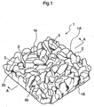
- the high strength porous concrete structure 1 in accordance with the invention is, as shown in Figs. 1 and 2, that a plurality of lumps 2 whose configuration conforms to a configuration of rough aggregates as an original material to be transferred are interconnected and exposed to a surface 1a of the high strength porous concrete structure 1 and a gap 3 formed between the lumps 2 is through to a back side 2b of the lumps 2, and is characterized by that the lumps 2 are integrally made of the same concrete tissue 4.
- At least a surface portion 1A of the high strength porous concrete structure 1 becomes porous because of its stereostructure formed by a plurality of lumps 2 whose configuration conform to the original material to be transferred and the gap 3 which is through to the back side 2b of the lumps 2.
- the surface portion 1A produces an effect of water permeability and if the high strength porous concrete structure 1 is used as a wall or a block for acoustic, the surface portion 1A produces an effect of sound-absorbing.
- the gap 3 formed between the lumps 2 works as a space to keep a plant seed, soil or a fertilizer.
- the gap 3 works as a space to breed algae for water purification or a space to keep a catalyst for gas absorption.
- the high strength porous concrete structure 1 can also be used as a decorative board for building because its appearance closely resembles to that of a conventional porous concrete structure 6 which is made of cement, rough aggregates 10 and water, and each of which is kneaded and cured as shown in Fig. 10.
- the high strength porous concrete structure 1 has such an arrangement in which each of the lumps 2 is made of the same concrete tissue 4 and the lumps 2 being exposed to the surface 1a are integrally formed.
- a bond strength between the lumps 2 on the surface of the high strength porous concrete structure 1 is very high beyond comparison with that of the conventional porous concrete structure 6 where each of the rough aggregates 10 is connected with a thin cement paste layer 11 and kept in contact at a point. Therefore the high strength porous concrete structure 1 shows a far higher reading in both flexural strength and compressive strength than that of the conventional porous concrete structure 6. Fly loss also can easily be improved when it is used as a pavement.
- porous concrete tissue comprising rough aggregates and cement paste should be provided in order to form a water permeable layer on a surface side of the pavement and an ordinal concrete tissue comprising rough aggregates, fine aggregates and cement paste should be provided under the porous concrete tissue in order to form a solid tight layer which does not permeate water.
- a porous concrete tissue comprising rough aggregates and cement paste should be provided in order to form a layer having a sound absorbing function on a surface side of the sound insulating board and an ordinal concrete tissue comprising rough aggregates, fine aggregates and cement paste should be provided back of the porous concrete tissue in order to form a solid tight layer which insulates sound.
- the high strength porous concrete structure 1 of the invention has an arrangement wherein the lumps 2 whose configuration conforms to rough aggregates as an original material to be transferred are made of the same concrete tissue 4.
- the backing portion 1B can be continuously and integrally formed with the lumps 2 of the same concrete tissue 4 as shown in Figs. 1 and 2.
- a porous concrete material comprising rough aggregates and cement paste for a surface portion and an ordinary concrete material for a backing portion separately, which makes it possible to form the porous surface portion 1A and the solid backing portion 1B simultaneously with a single process of placing concrete.
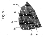
- the lump 2, as shown in Fig. 3 where a magnified cross section of a part of the lump 2 is shown, may have an arrangement where a plurality of continuous air bubbles 5 are entrained in concrete tissue 4 of the lump 2.
- the structure if used as a sound absorbing board, the effect of sound absorbing can be much improved.
- the weight of the structure can also be made lighter, thereby to make transportation or construction easy.
- the structure if used as a water purifying matrix, the structure can provide algae or microbes with a much larger residential area by means of the continuous air bubbles 5 a part 5a of which is open to the surface of the structure, thereby to improve the effect of water purification.
- the foaming agent may concretely be represented by, for example, metal aluminum powder, synthetic surface-active agent system, a resin soap system or a hydrolytic protein system.
- a method of manufacturing the high strength porous concrete structure can be represented by a method comprising the steps of putting a heated-to-melt thermoplastic material which cures at a normal temperature so as to be an elastically deformable form into contact with a surface of an object exposing an original material to be transferred such as a porous concrete structure using rough aggregates, curing the thermoplastic material so as to make the form, detaching the form from the object by making use of the elastic deformation of the form, placing an ordinal concrete material into the form and curing the concrete so as to obtain the above-mentioned high strength porous concrete structure.
- resin mortar or resin concrete whose binder is polyester or epoxy resin may be used in stead of the ordinal concrete material.
- the strength of the structure can be further improved.
- a porous concrete structure 6 as a conventional structure which contains rough aggregates 10 as an original material to be transferred in the center of a container 7 which is rectangle in a top plan view and then place a heated-to-melt thermoplastic material 8 into the container 7 from upward.
- the thermoplastic material 8 is, for example, "EM” (Trade Name; Manufactured by Sumitomo Osaka Cement Co., Ltd.).
- the "EM” is thermoplastic elastomerics where oil is confined in a three-dimensional mesh structure of special polymer, and which is rubber elastic at a normal temperature and liquid at a high temperature such as over 210 °C.
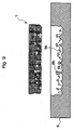
- thermoplastic material 8 pours the heated-to-melt thermoplastic material 8 into the container 7 and leave it for a while at a normal temperature so as to cure the thermoplastic material 8 as shown in Fig. 5. Then a form 9 made of rubber elastics is formed. Next detach the form 9 from the porous concrete structure 6 by making use of elastic deformation of the form 9 as shown in Fig. 6.
- thermoplastic material 8 which has been poured from the surface side of the porous concrete structure 6 goes into a gap 12 between a plurality of rough aggregates 10 which constitute the porous concrete structure 6, the thermoplastic material 8 is made into the form 9 having a concave portion 9a which corresponds to the configuration of the rough aggregate 10 and a soft projection 9b which corresponds to the configuration of the gap 12 as shown in Figs. 6 and 7. Then place mortar or concrete 13 into the form 9 and cure it as shown in Fig. 8 so that the high strength porous concrete structure 1 of the invention shown in Fig. 9 is manufactured.
- the high strength porous concrete structure 1 can easily be detached from the form 9 by making use of elastic deformation of the form 9 which is rubber elastics.
- FIG. 11 Another embodiment of this invention especially as a structure used for water permeable or draining pavement may be represented by a high strength porous concrete structure 101, as shown in Figs. 11 and 12, comprising a surface layer 101A and a backing layer 101B which is united with the surface layer 101A and which has water permeability
- the surface layer 101A comprises, like the above-descried, a plurality of lumps 102 having a configuration of an original material to be transferred such as rough aggregates and each of which is interconnected and exposed to a surface 101Aa of the surface layer 101A and integrally formed by the same concrete tissue 104, and a gap 103 which is formed between the lumps 102 and which is through from the surface 101Aa of the surface layer 101A to a boundary X between the surface layer 101A and the backing layer 101B.
- the surface layer 101A is porous because of stereostructure formed by the gap 103 between a plurality of lumps 102 so that the surface layer 101A has water permeability.
- the backing layer 101B is water permeable and united with the surface layer 101A and the gap 103 is through to the boundary X between the surface layer 101A and the backing layer 101B, the high strength porous concrete structure 101 has water permeability as a whole when used as a pavement.
- the backing layer 101B is made of porous concrete 161 using rough aggregates 110 as shown in Fig. 12, the backing layer 101B has water permeability.
- the high strength porous concrete structure 101 can produce an effect of water permeability.
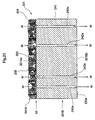
- the backing layer 101B is made of solid tight concrete tissue 241, 341 where a water through hole 242a, 342a, 342b is provided as shown in Fig. 20 or Fig. 21, the high strength porous concrete structure 201, 301 can produce an effect of water permeability or a draining function depending on the configuration of the water though hole 242a, 342a, 342b.
- resin mortar or resin concrete whose binder is polyester or epoxy resin can also be used in stead of ordinal concrete material. If so, the strength of the high strength porous concrete structure will be further improved.
- the high strength porous concrete structure in accordance with the invention has a porous surface portion because of the arrangement in which a plurality of lumps whose surface configuration is similar to a configuration of an original material to be transferred such as rough aggregates are arranged all over the thickness of the high strength porous concrete structure and each of which is interconnected and exposed to the surface of the high strength porous concrete and are made of the same concrete tissue and the gap formed between the lumps is through to a back side of the lumps, it produces an effect of water permeability when used as a pavement and it produces an effect of sound absorbing when used as a wall or a block for acoustic. In addition, it can produce a suitable effect if applied to a block for plants, a riverbed block, a water purifying matrix, a gas absorbing matrix or a decorative board for building.
- each of the lumps is interconnected and made of the same concrete tissue, the bond strength of the lumps is very high when compared with that of the conventional structure and both of the readings of the flexural and compressive strength on the whole are also very high.
- the fly loss can be effectively improved if the high strength porous concrete structure, is applied to pavements.
- the high strength porous concrete structure has an arrangement in which the plurality of lumps corresponding to the original material to be transferred such as rough aggregates are made of the same concrete tissue, the backing layer portion can be integrally and continuously made of the same concrete tissue as that of the lumps when the solid tight backing layer portion is formed back side of the porous surface layer portion.
- the porous surface layer portion and the solid tight backing layer portion can be formed with one single process of placing concrete.
- the high strength porous concrete structure having the solid tight backing layer can produce a suitable effect of draining or sound proof when used as a draining pavement or a sound proof wall.
- the bubbles can increase the effect of sound absorbing when the high strength porous concrete structure is applied to sound absorbing boards.
- the weight of the structure can be made lighter, which makes transportation or construction easy.
- the structure can provide algae or microbes with a much larger residential area by means of the continuous air bubbles a part of which is open to the surface of the structure, thereby to improve the effect of water purification.
- a method of manufacturing the high strength porous concrete structure comprises the steps of putting a heated-to-melt thermoplastic material which cures so as to be an elastically deformable form at a normal temperature into contact with a surface of an object exposing an original material to be transferred such as a porous concrete structure using rough aggregates, curing the thermoplastic material so as to make the form, detaching the form from the object by making use of the elastic deformation of the form, placing mortar or concrete into the form and curing the mortar or concrete, the high strength porous concrete structure in accordance with claim 1 can be manufactured with ease and accuracy.
- the high strength porous concrete structure in accordance with claim 5 can be manufactured with ease.
- the high strength porous concrete structure comprises a surface layer and a backing layer having an effect of water permeability or draining and which is united with the surface layer, wherein the surface layer has an arrangement in which a plurality of lumps whose configuration is that of rough aggregates as an original material to be transferred are interconnected and exposed to the surface of the surface layer and a gap formed between the lumps is through to a back side of the lumps and the lumps are integrally made of the same concrete tissue, at least the surface layer becomes porous because of its stereostructure formed by a plurality of lumps and the gap between the lumps. Therefore, the high strength porous concrete structure can be used as a pavement which is especially superior in water permeability or draining effect.
- the backing layer is made of porous concrete using rough aggregates, the backing layer produces an effect of water permeability, thereby to give an effect of water permeability to the high strength porous concrete structure in accordance with the invention.
- the backing layer is made of a solid tight concrete tissue with which a water through hole is provided, the backing layer produces an effect of water permeability or draining depending on a shape of the water through hole, thereby to give an effect of water permeability or draining to the high strength porous concrete structure in accordance with the invention.
- a method comprises the steps of putting a heated-to-melt thermoplastic material which cures so as to be an elastically deformable form at a normal temperature into contact with a surface of an object exposing an original material to be transferred such as a porous concrete structure using rough aggregates, curing the thermoplastic material so as to make the form, detaching the form from the object by making use of the elastic deformation of the form, placing mortar or concrete into the form and curing the mortar or concrete so as to form the surface layer of the structure.
- the high strength porous concrete structure can also be manufactured by arranging the above-mentioned form in a base of a container, placing mortar or concrete in the form, curing the mortar or concrete so as to form a surface layer and then placing porous concrete having rough aggregates over the surface layer so as to form a backing layer.
- Compound and knead rough aggregates having a diameter of 10 to 20 mm, Portland cement and water into concrete with the ratio of water to the Portland cement 28 % and the ratio of the Portland cement to the rough aggregates 17 % where the unit cement weight is 260 kg/m 3 and the unit rough aggregate weight is 1560 kg/m 3 .
- the porous concrete structure had a porous arrangement where each of the rough aggregates was connected with cement paste and kept in a contact at a point and voids thereof was 20 to 30 %.
- the porous concrete in accordance with the comparison example 1 showed as follows: The compressive strength read 100 to 200 Kgf/cm 2 , the flexural strength read 15 to 20 kgf/cm 2 and the fly loss read 20 to 40 %.
- the fly loss shows a resistance of an aggregate to detaching or flying loss caused by means of a load of a tire and was measured in accordance with the Cantabro Test. More particularly, the fly loss was measured by making a cylinder under test having a diameter of 10 cm and height of 5 cm, arranging the cylinder in a Los Angeles test machine, rotating a drum 300 times without using a steel sphere and measuring the mass of the cylinder after rotated so as to get a percentage of lost mass to the mass prior test.
- Compound and knead rough aggregates having a diameter of 2 to 10 mm, Portland cement and water with the ratio of water to the Portland cement 30 % and the ratio of the Portland cement to the rough aggregates 20 % where the unit cement weight is 295 kg/m 3 and the unit rough aggregate weight is 1500 kg/m 3 .
- the porous concrete structure had a porous structure where each of the rough aggregates was connected with cement paste and kept in a contact at a point and voids thereof was 15 to 25 %.
- the porous concrete in accordance with the comparison example 2 showed as follows: The compressive strength read 100 to 200 Kgf/cm 2 , the flexural strength read 20 to 25 kgf/cm 2 and the fly loss read 15 to 30%.
- Compound and knead rough aggregates having a diameter of 2 to 5 mm, Portland cement and water with the ratio of water to the Portland cement 25 % and the ratio of the Portland cement to the rough aggregates 40 % where the unit cement weight is 470 kg/m 3 and the unit rough aggregate weight is 1150 kg/m 3 .
- the porous concrete structure had a porous structure where each of the rough aggregates was connected with cement paste and kept in a contact at a point and voids thereof was 15 %.
- the conventional porous concrete in accordance with the comparison example 3 showed as follows: The compressive strength read 250 to 300 Kgf/cm 2 , the flexural strength read 30 to 40 kgf/cm 2 and the fly loss read 10 to 20 %.
- the high strength porous concrete structure 1 had almost the same appearance as that of the conventional porous concrete structure since it was transferred through the above-mentioned form from the configuration of the matrix.
- the high strength porous concrete structure 1 in accordance with the embodiment 1 comprised a porous surface layer of 25 mm in thickness and a tight solid backing layer of 25 mm in thickness. The voids of the porous surface layer was approximate 20%.
- the high strength porous concrete in accordance with the embodiment 1 showed as follows: The compressive strength read 300 to 400 Kgf/cm 2 , the flexural strength read 40 to 60 kgf/cm 2 and the fly loss read 5 % or below.
- Compound and knead aggregates having a diameter of 0 to 10 mm, Portland cement and water into concrete with the ratio of water to the Portland cement 30 % where the unit cement weight is 440 kg/m 3 and the unit aggregate weight is 1200 kg/m 3 .
- the high strength porous concrete structure in accordance with the embodiment 2 comprised a porous surface layer of 15 mm in thickness and a tight solid backing layer of 35 mm in thickness. The voids of the porous surface layer was approximate 20 %.
- the high strength porous concrete in accordance with the embodiment 2 showed as follows: The compressive strength read 400 to 500 Kgf/cm 2 , the flexural strength read 50 to 70 kgf/cm 2 and the fly loss read 5 % or below.
- a rubber latex, a thermoplastic dispersion or a thermosetting dispersion may be used as a latex for such polymer cement.
- the high strength porous concrete structure in accordance with the embodiment 3 comprised a porous surface layer of 25 mm in thickness and a tight solid backing layer of 25 mm in thickness. The voids of the porous surface layer was approximate 20%.
- the high strength porous concrete in accordance with the embodiment 3 showed as follows: The compressive strength read 400 to 500 Kgf/cm 2 , the flexural strength read 100 to 160 kgf/cm 2 and the fly loss read 5 % or below.
- Compound and knead aggregates having a diameter of 0 to 5 mm, Portland cement and water into light-weight bubble mortar to which aluminum powder or a foaming agent as an air entraining agent is introduced little by little with the ratio of water to the cement 45 % where the unit cement weight is 400 to 500 kg/m 3 and the unit aggregate weight is 200 to 300 kg/m 3 .
- the high strength porous concrete structure in accordance with the embodiment 4 comprised a porous surface layer of 25 mm in thickness and a tight solid backing layer of 25 mm in thickness.
- the voids of the porous surface layer was approximate 50 to 80 %.
- the high strength porous concrete in accordance with the embodiment 4 showed as follows: The compressive strength read 50 to 100 Kgf/cm 2 , the flexural strength read 10 to 30 kgf/cm 2 and the fly loss read 30 to 60 % or below.
- the high strength porous concrete is suitable for a sound-proofing material which does not require high strength.
- Table 1 shows the combination and strength of the comparison examples 1, 2 and 3 and table 2 shows the combination and strength of the embodiments 1, 2, 3 and 4. Combination and Strength of Comparison Examples 1, 2, 3 and 4 Comparison Example 1 Comparison Example 2 Comparison Example 3 Diameter of Aggregate (mm) 10 ⁇ 20 2 ⁇ 10 2 ⁇ 5 Ratio of Water to Cement (%) 28 30 25 Ratio of Cement to Aggregate (%) 17 20 40 Unit Cement weight (Kg/m 3 ) 260 295 470 Unit Aggregate Weight (Kg/m 3 ) 1560 1500 1150 Unit Latex Weight(KG/m 3 ) Voids (%) 20 ⁇ 30 15 ⁇ 25 15 Compressive Strength (Kgf/cm 2 ) 100 ⁇ 200 100 ⁇ 200 250 ⁇ 300 Flexural Strength (kgf/cm 2 ) 15 ⁇ 20 25 ⁇ 25 30 ⁇ 40 Fly Loss (Weight Loss Rate) 20 ⁇ 40% 15 ⁇ 30% 10 ⁇ 20% Combination and Strength of Embodiments 1, 2, 3 and 4 Embodiment 1 Embodiment 2 Embodiment 3 Embodi
- the embodiments 1, 2 and 3 showed a very high value in both of the compressive strength and the flexural strength and a good value in the fly loss when compared to the conventional comparison examples 1, 2 and 3 although the voids were almost the same. Generally it is considered acceptable for pavements if fly loss is 30 % or below. As a result of this, the embodiments 1, 2 and 3 are suitable for pavement since each of the fly loss showed 5 % or below.
- the embodiment 4 is not suitable for pavements since it is low in both the compressive strength and the flexural strength and the fly loss thereof is 30 to 60 %. However, the embodiment 4 has a large surface area which is exposed to outside as well as it is light, since the voids thereof are high such as 50 to 80 %. As a result of this, it is suitable for sound absorbing material which does not require high strength and can be expected to produce a high sound absorbing effect. It is suitable also for purifying water since the porous structure can effectively provide residential areas for algae or fungi.
- the high strength porous concrete structure 101 shown in Figs. 11 and 12 comprises a surface layer 101A made of concrete tissue 104 and a backing layer 101B made of conventional porous concrete 162 and which is united with the surface layer 101A.
- a plurality of lumps 102 having a configuration of rough aggregates each of which is interconnected and exposed to a surface 101Aa of the surface layer 101A and between the lumps 102 formed is a gap 103 which is through from the surface 101Aa to a boundary X between the surface layer 101A and the backing layer 101B.
- the surface layer 101A of the high strength porous concrete structure 101 is similar to that of the high strength porous structure 1 in accordance with the embodiment 1 and manufactured by the following procedures.
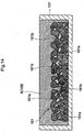
- manufacture a form 109 by means of a procedure similar to the embodiment 1 by using the conventional porous concrete structure 6 in accordance with the comparison example 1 as a matrix for the form 109. More specifically, as shown in Fig. 13, place the porous concrete structure 6 in a container 107, pour a thermoplastic material into the container 107 and leave it for a while at a room temperature until the thermoplastic material 8 cures. Then the form 109 is manufactured as shown in Fig. 14. Detach the form 109 from an original material 161 to be transferred by making use of plastic deformation of the form 109.
- a concave portion 109a whose configuration corresponds to that of the rough aggregates 161a and a soft projection 109b whose configuration corresponds to that of the gap 161b between the rough aggregates 161a.
- Thus manufactured high strength porous concrete structure 101 of this embodiment has a water permeability on the whole since the gap 103 formed between the lumps 102 of the surface layer 101A is through from the surface 101Aa of the surface layer 101A to the boundary X between the surface layer 101A and the backing layer 101B. More specifically, as shown in Fig. 12. water W which soaks into the surface 101Aa of the surface layer 101A goes down along the gap 103 of the surface layer 101A, passes the boundary X and reaches a gap 112 of the backing layer 101B so as to be discharged to outside.
- the high strength porous concrete structure 101 Although having generally the same voids as those of the comparison examples 1, 2 and 3, the high strength porous concrete structure 101 showed a satisfactory reading in flying loss, namely, 5 % or below like embodiment 1. As a result of this, the high strength porous concrete structure 101 is suitable for pavements.
- the high strength porous concrete structure 101 In order to apply the high strength porous concrete structure 101 to a pavement one piece of the high strength porous concrete structures 101 is used as one unit structure and a plurality of the high strength porous concrete structures 101 are placed continuously with its surface layer 101A exposing to the surface of the pavement. As described above, the fly loss showed a very satisfactory reading. As a result of this, the pavement using the high strength porous concrete structure 101 can prevent the surface 101Aa of the surface layer 101A from detaching to fly when a big stress is applied to the surface of the pavement when vehicles brake. Therefore, the high strength porous concrete structure 101 can suitably be applied to pavements in respect to both water permeability and strength.
- a solid tight concrete layer 101C may be formed under the base 101Bb of the backing layer 101B as shown in Fig. 19.
- water W which soaks into the surface 101Aa of the surface layer 101A goes down, as shown by an arrow in Fig. 19, through a gap 103 of the surface layer 101A and a gap 112 of the backing layer 101B and to a boundary Y between the backing layer 101B and a concrete layer 101C so as to be discharged from drainage not shown in drawings.
- the high strength porous concrete structure 1011 can be used as an excellent pavement.
- Fig. 20 shows a high strength porous concrete structure 201 which comprises a surface layer 201A made of concrete tissue 204 and a backing layer 201B made of solid tight concrete tissue 241 and which is united with the surface layer 201A.
- a surface layer 201A made of concrete tissue 204 and a backing layer 201B made of solid tight concrete tissue 241 and which is united with the surface layer 201A.
- On the surface layer 201A provided are a plurality of lumps 202 having a configuration of a rough aggregate each of which are interconnected and exposed to a surface of the high strength porous concrete structure. Between the lumps 202 formed is a gap which is connected from the face 201Aa to a boundary X2 to the backing layer 201B.
- the backing layer 201B is provided with a plurality of water permeable holes 242a as a water through hole which penetrates the base 201Bb of the backing layer 201B through the boundary X2.
- the fly loss of the high strength porous concrete structure 201 is suitable for a pavement. Since water W which soaks into the surface 201Aa of the surface layer 201A goes down to a boundary X 2 between the surface layer 201A and the backing layer 201B through the gap 203, as shown by an arrow in Fig. 20, and then is discharged through the water permeable hole 242a to underground, the high strength porous concrete structure 201 is excellent in water permeability. As a result of this, the high strength porous concrete structure 201 can be used as an extremely good pavement because of its water permeability and strength.
- the high strength porous concrete structure 201 may be, as shown in Fig. 21, provided with a plurality of water permeable holes 342a each of which begins with a boundary X3 between the surface layer 201A and the backing layer 301B and end with an extending end which does not reach the base surface 301Bb of the backing layer 301B and a discharging hole 342b which connects each of the extending ends of the water permeable holes 342a.
- the high strength porous concrete structure 301 shows an excellent performance in water permeability.
- the high strength porous concrete structure 301 can be used as pavements because of its water permeability and strength.
- the backing layers 201B and 301B made of solid tight concrete tissue 241 and 341 are provided with the water permeable holes 242a, 342a and 342b, form a form and a surface layer as the same method of the embodiment 5, form the water permeable holes 242a, 342s or 243b by setting up a pipe or something like that prior to curing the mortar of the surface layer, and then place concrete tissue 203, 241 or 341 in the form.
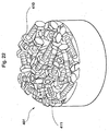
- the original material to be transferred is not limited to the the above-described porous concrete structure, but may be a bolt 410, a nut 411, or a metal lump such as a tool so as to obtain a high strength porous concrete structure 401 as shown in Fig. 22.
- the original material to be transferred may be a glass lump such as a marble, a ceramic lump or a synthetic resin lump.
Description
- This invention relates to a high strength porous concrete structure which is applied to a water permeable pavement, a draining pavement, a sound insulating board, a sound-proofing barrier, a sound absorbing block for acoustic, a block for plants, a riverbed block, a water purifying matrix, a gas absorbing matrix, a decorative board for building, a fish reef, a block for fish reef or a block for breeding algae and to a method of manufacturing the high strength porous concrete structure.
- Porous concrete structures are conventionally, for example, made of cement, rough aggregates and water, and each of which is kneaded and cured to be used for water permeable pavements or draining pavements.
- However, the porous concrete structures have such an arrangement in which each of the rough aggregates is connected with cement paste and kept in contact at a point. As a result, the porous concrete structures are low in both flexural strength and compressive strength and also it is difficult to increase resistance to fly loss. In other words, for a pavement made of the porous concrete structure having the above arrangement it easily causes fly loss of rough aggregates locating on the surface thereof when a big stress is applied to the surface thereof every time vehicles frequently brake.
- Further since the porous concrete structures have a porous arrangement, resistance to a freeze-thaw effect is very low. Therefore, it is not recommendable to use the porous concrete structures in a cold district.
-
FR 1 418 451 A discloses the features of the preamble ofclaim 1. - In order to solve the above-mentioned problems, the invention is defined by the features of
claim 1. - The invention is also intended to provide a method of manufacturing the high strength porous concrete structure according to features of
claim 4. - The high strength
porous concrete structure 1 in accordance with the invention is, as shown in Figs. 1 and 2, that a plurality oflumps 2 whose configuration conforms to a configuration of rough aggregates as an original material to be transferred are interconnected and exposed to asurface 1a of the high strengthporous concrete structure 1 and agap 3 formed between thelumps 2 is through to aback side 2b of thelumps 2, and is characterized by that thelumps 2 are integrally made of thesame concrete tissue 4. - In accordance with the arrangement, at least a
surface portion 1A of the high strengthporous concrete structure 1 becomes porous because of its stereostructure formed by a plurality oflumps 2 whose configuration conform to the original material to be transferred and thegap 3 which is through to theback side 2b of thelumps 2. As a result of this, if the high strengthporous concrete structure 1 is used, for example, as a pavement, thesurface portion 1A produces an effect of water permeability and if the high strengthporous concrete structure 1 is used as a wall or a block for acoustic, thesurface portion 1A produces an effect of sound-absorbing. In addition, if the the high strengthporous concrete structure 1 is used as a block for plants or a riverbed block, thegap 3 formed between thelumps 2 works as a space to keep a plant seed, soil or a fertilizer. Further if the high strengthporous concrete structure 1 is used as a water purifying matrix or a gas absorbing matrix, thegap 3 works as a space to breed algae for water purification or a space to keep a catalyst for gas absorption. From the viewpoint of its appearance, the high strengthporous concrete structure 1 can also be used as a decorative board for building because its appearance closely resembles to that of a conventionalporous concrete structure 6 which is made of cement,rough aggregates 10 and water, and each of which is kneaded and cured as shown in Fig. 10. - Unlike the conventional
porous concrete structure 6, the high strengthporous concrete structure 1 has such an arrangement in which each of thelumps 2 is made of thesame concrete tissue 4 and thelumps 2 being exposed to thesurface 1a are integrally formed. As a result of this, a bond strength between thelumps 2 on the surface of the high strengthporous concrete structure 1 is very high beyond comparison with that of the conventionalporous concrete structure 6 where each of therough aggregates 10 is connected with a thincement paste layer 11 and kept in contact at a point. Therefore the high strengthporous concrete structure 1 shows a far higher reading in both flexural strength and compressive strength than that of the conventionalporous concrete structure 6. Fly loss also can easily be improved when it is used as a pavement. - In addition, if a conventional porous concrete structure is used as a draining pavement or a sound insulating board, it has to be made two-layered, thereby to complicate a manufacturing process. More particularly, in case used as the draining pavement, porous concrete tissue comprising rough aggregates and cement paste should be provided in order to form a water permeable layer on a surface side of the pavement and an ordinal concrete tissue comprising rough aggregates, fine aggregates and cement paste should be provided under the porous concrete tissue in order to form a solid tight layer which does not permeate water. Similarly, in case used as the sound insulating board, a porous concrete tissue comprising rough aggregates and cement paste should be provided in order to form a layer having a sound absorbing function on a surface side of the sound insulating board and an ordinal concrete tissue comprising rough aggregates, fine aggregates and cement paste should be provided back of the porous concrete tissue in order to form a solid tight layer which insulates sound. As mentioned above, it is inevitable to place concrete material of different combination at least twice in order to form a two-layered structure comprising a porous concrete layer made of rough aggregates and cement paste and an ordinal solid concrete layer. This causes a problem of increasing a number of processing steps and of lacking integrity because of two-layered structure.
- In order to solve the above problems the high strength
porous concrete structure 1 of the invention has an arrangement wherein thelumps 2 whose configuration conforms to rough aggregates as an original material to be transferred are made of thesame concrete tissue 4. As a result, in case that a solidtight backing portion 1B is to be formed back of theporous surface portion 1A, thebacking portion 1B can be continuously and integrally formed with thelumps 2 of thesame concrete tissue 4 as shown in Figs. 1 and 2. Then there is no need to place a porous concrete material comprising rough aggregates and cement paste for a surface portion and an ordinary concrete material for a backing portion separately, which makes it possible to form theporous surface portion 1A and thesolid backing portion 1B simultaneously with a single process of placing concrete. - In one form of the embodiment, the
lump 2, as shown in Fig. 3 where a magnified cross section of a part of thelump 2 is shown, may have an arrangement where a plurality ofcontinuous air bubbles 5 are entrained inconcrete tissue 4 of thelump 2. In accordance with the arrangement, if the structure is used as a sound absorbing board, the effect of sound absorbing can be much improved. In addition the weight of the structure can also be made lighter, thereby to make transportation or construction easy. Further, if used as a water purifying matrix, the structure can provide algae or microbes with a much larger residential area by means of thecontinuous air bubbles 5 apart 5a of which is open to the surface of the structure, thereby to improve the effect of water purification. - As explained above, in order to manufacture the high strength porous concrete structure inside of which a plurality of air bubbles are included, it is preferable to mix a foaming agent into concrete or mortar in order to entrain a plurality of air bubbles into the concrete or mortar. The foaming agent may concretely be represented by, for example, metal aluminum powder, synthetic surface-active agent system, a resin soap system or a hydrolytic protein system.
- A method of manufacturing the high strength porous concrete structure can be represented by a method comprising the steps of putting a heated-to-melt thermoplastic material which cures at a normal temperature so as to be an elastically deformable form into contact with a surface of an object exposing an original material to be transferred such as a porous concrete structure using rough aggregates, curing the thermoplastic material so as to make the form, detaching the form from the object by making use of the elastic deformation of the form, placing an ordinal concrete material into the form and curing the concrete so as to obtain the above-mentioned high strength porous concrete structure. In this case resin mortar or resin concrete whose binder is polyester or epoxy resin may be used in stead of the ordinal concrete material. In accordance with the arrangement, the strength of the structure can be further improved.
- The method will now concretely be described with reference to drawings. As shown in Fig. 4, place a
porous concrete structure 6 as a conventional structure which containsrough aggregates 10 as an original material to be transferred in the center of acontainer 7 which is rectangle in a top plan view and then place a heated-to-meltthermoplastic material 8 into thecontainer 7 from upward. - In this case, the
thermoplastic material 8 is, for example, "EM" (Trade Name; Manufactured by Sumitomo Osaka Cement Co., Ltd.). The "EM" is thermoplastic elastomerics where oil is confined in a three-dimensional mesh structure of special polymer, and which is rubber elastic at a normal temperature and liquid at a high temperature such as over 210 °C. - As mentioned above, pour the heated-to-melt
thermoplastic material 8 into thecontainer 7 and leave it for a while at a normal temperature so as to cure thethermoplastic material 8 as shown in Fig. 5. Then aform 9 made of rubber elastics is formed. Next detach theform 9 from theporous concrete structure 6 by making use of elastic deformation of theform 9 as shown in Fig. 6. Since thethermoplastic material 8 which has been poured from the surface side of theporous concrete structure 6 goes into agap 12 between a plurality ofrough aggregates 10 which constitute theporous concrete structure 6, thethermoplastic material 8 is made into theform 9 having aconcave portion 9a which corresponds to the configuration of therough aggregate 10 and asoft projection 9b which corresponds to the configuration of thegap 12 as shown in Figs. 6 and 7. Then place mortar orconcrete 13 into theform 9 and cure it as shown in Fig. 8 so that the high strengthporous concrete structure 1 of the invention shown in Fig. 9 is manufactured. The high strengthporous concrete structure 1 can easily be detached from theform 9 by making use of elastic deformation of theform 9 which is rubber elastics. - Another embodiment of this invention especially as a structure used for water permeable or draining pavement may be represented by a high strength
porous concrete structure 101, as shown in Figs. 11 and 12, comprising asurface layer 101A and abacking layer 101B which is united with thesurface layer 101A and which has water permeability wherein thesurface layer 101A comprises, like the above-descried, a plurality oflumps 102 having a configuration of an original material to be transferred such as rough aggregates and each of which is interconnected and exposed to a surface 101Aa of thesurface layer 101A and integrally formed by thesame concrete tissue 104, and agap 103 which is formed between thelumps 102 and which is through from the surface 101Aa of thesurface layer 101A to a boundary X between thesurface layer 101A and thebacking layer 101B. In accordance with the arrangement, at least thesurface layer 101A is porous because of stereostructure formed by thegap 103 between a plurality oflumps 102 so that thesurface layer 101A has water permeability. In addition, since thebacking layer 101B is water permeable and united with thesurface layer 101A and thegap 103 is through to the boundary X between thesurface layer 101A and thebacking layer 101B, the high strengthporous concrete structure 101 has water permeability as a whole when used as a pavement. - In this case if the
backing layer 101B is made ofporous concrete 161 usingrough aggregates 110 as shown in Fig. 12, thebacking layer 101B has water permeability. As a result, the high strengthporous concrete structure 101 can produce an effect of water permeability. If thebacking layer 101B is made of solidtight concrete tissue hole porous concrete structure hole - As described above, since the high strength porous concrete structure in accordance with the invention has a porous surface portion because of the arrangement in which a plurality of lumps whose surface configuration is similar to a configuration of an original material to be transferred such as rough aggregates are arranged all over the thickness of the high strength porous concrete structure and each of which is interconnected and exposed to the surface of the high strength porous concrete and are made of the same concrete tissue and the gap formed between the lumps is through to a back side of the lumps, it produces an effect of water permeability when used as a pavement and it produces an effect of sound absorbing when used as a wall or a block for acoustic. In addition, it can produce a suitable effect if applied to a block for plants, a riverbed block, a water purifying matrix, a gas absorbing matrix or a decorative board for building.
- Further, since each of the lumps is interconnected and made of the same concrete tissue, the bond strength of the lumps is very high when compared with that of the conventional structure and both of the readings of the flexural and compressive strength on the whole are also very high. The fly loss can be effectively improved if the high strength porous concrete structure, is applied to pavements.
- Since the high strength porous concrete structure has an arrangement in which the plurality of lumps corresponding to the original material to be transferred such as rough aggregates are made of the same concrete tissue, the backing layer portion can be integrally and continuously made of the same concrete tissue as that of the lumps when the solid tight backing layer portion is formed back side of the porous surface layer portion. As a result, there is no need of placing a porous concrete material comprising rough aggregates and cement past and an ordinal concrete material for the backing layer portion. The porous surface layer portion and the solid tight backing layer portion can be formed with one single process of placing concrete. The high strength porous concrete structure having the solid tight backing layer can produce a suitable effect of draining or sound proof when used as a draining pavement or a sound proof wall.
- If a plurality of continuous air bubbles are entrained in concrete tissue as well as the above-described gap, the bubbles can increase the effect of sound absorbing when the high strength porous concrete structure is applied to sound absorbing boards. In addition, the weight of the structure can be made lighter, which makes transportation or construction easy. Further, if used as a water purifying matrix, the structure can provide algae or microbes with a much larger residential area by means of the continuous air bubbles a part of which is open to the surface of the structure, thereby to improve the effect of water purification.
- In manufacturing the above-mentioned high strength porous concrete structure if a method of manufacturing the high strength porous concrete structure comprises the steps of putting a heated-to-melt thermoplastic material which cures so as to be an elastically deformable form at a normal temperature into contact with a surface of an object exposing an original material to be transferred such as a porous concrete structure using rough aggregates, curing the thermoplastic material so as to make the form, detaching the form from the object by making use of the elastic deformation of the form, placing mortar or concrete into the form and curing the mortar or concrete, the high strength porous concrete structure in accordance with
claim 1 can be manufactured with ease and accuracy. - If a plurality of air bubbles are entrained into mortar or concrete by mixing foaming agent into the mortar or concrete, the high strength porous concrete structure in accordance with
claim 5 can be manufactured with ease. - If the high strength porous concrete structure comprises a surface layer and a backing layer having an effect of water permeability or draining and which is united with the surface layer, wherein the surface layer has an arrangement in which a plurality of lumps whose configuration is that of rough aggregates as an original material to be transferred are interconnected and exposed to the surface of the surface layer and a gap formed between the lumps is through to a back side of the lumps and the lumps are integrally made of the same concrete tissue, at least the surface layer becomes porous because of its stereostructure formed by a plurality of lumps and the gap between the lumps. Therefore, the high strength porous concrete structure can be used as a pavement which is especially superior in water permeability or draining effect.
- In this case, if the backing layer is made of porous concrete using rough aggregates, the backing layer produces an effect of water permeability, thereby to give an effect of water permeability to the high strength porous concrete structure in accordance with the invention. If the backing layer is made of a solid tight concrete tissue with which a water through hole is provided, the backing layer produces an effect of water permeability or draining depending on a shape of the water through hole, thereby to give an effect of water permeability or draining to the high strength porous concrete structure in accordance with the invention.
- In manufacturing the high strength porous concrete structure which can be used for water permeable of draining pavements a method comprises the steps of putting a heated-to-melt thermoplastic material which cures so as to be an elastically deformable form at a normal temperature into contact with a surface of an object exposing an original material to be transferred such as a porous concrete structure using rough aggregates, curing the thermoplastic material so as to make the form, detaching the form from the object by making use of the elastic deformation of the form, placing mortar or concrete into the form and curing the mortar or concrete so as to form the surface layer of the structure. The high strength porous concrete structure can also be manufactured by arranging the above-mentioned form in a base of a container, placing mortar or concrete in the form, curing the mortar or concrete so as to form a surface layer and then placing porous concrete having rough aggregates over the surface layer so as to form a backing layer.
- In any case of the above, if resin mortar or resin concrete whose binder is polyester or epoxy resin is used in stead of mortar or concrete, the strength of the high strength porous concrete structure can be further improved.
-
- Fig. 1 is a referential perspective view showing a preferred embodiment of this invention.
- Fig. 2 is a cross sectional view of Fig. 1 taken along line A-A.
- . Fig. 3 is a magnified partial cross sectional view of a lump showing the preferred embodiment of the invention.
- Fig. 4 is a view to explain a method of manufacturing the high strength porous concrete structure in accordance with the embodiment of the invention.
- Fig. 5 is a view to explain the above-mentioned method.
- Fig. 6 is a view to explain the above-mentioned method.
- Fig. 7 is a referential perspective view showing a form used by the above-mentioned method.
- Fig. 8 is a view to explain the above-mentioned method.
- Fig. 9 is a view to explain the above-mentioned method.
- Fig. 10 is a cross sectional view showing a conventional porous concrete structure.
- Fig. 11 is a perspective view showing the
embodiment 5 of the invention. - Fig. 12 is a cross sectional view of Fig. 11 taken along line B-B.
- Fig. 13 is a view to explain a method of manufacturing a high strength porous concrete structure in accordance with another embodiment of the invention.
- Fig. 14 is a view to explain the above-mentioned method.
- Fig. 15 is a view to explain the above-mentioned method.
- Fig. 16 is a view to explain the above-mentioned method.
- Fig. 17 is a view to explain the above-mentioned method.
- Fig. 18 is a view to explain the above-mentioned method.
- Fig. 19 is a cross sectional view showing the high strength porous concrete structure in accordance with the embodiment with which a function of draining is provided.
- Fig. 20 is a cross sectional view showing further different embodiment of the invention.
- Fig. 21 is a cross sectional view showing the high strength porous concrete structure in accordance with the further different embodiment with which a function of draining is provided.
- Fig. 22 is a referential perspective view showing another different embodiment of the invention.
-
- An embodiment of the invention will now be concretely described below.
- First, manufacture a conventional porous concrete structure (examples 1, 2 and 3 for comparison) which is to be an original material to be transferred. Next, make a form shown in Fig. 7 by means of a procedure shown in Fig. 4 through Fig. 6 using the conventional porous concrete structure. Then place a concrete material having the following mixing rate into the form so as to obtain each of high strength porous concrete structures (
embodiments - Compound and knead rough aggregates having a diameter of 10 to 20 mm, Portland cement and water into concrete with the ratio of water to the Portland cement 28 % and the ratio of the Portland cement to the rough aggregates 17 % where the unit cement weight is 260 kg/m3 and the unit rough aggregate weight is 1560 kg/m3. Place the kneaded concrete into a predetermined form. Detach the concrete from the form after the concrete is cured so as to obtain a porous concrete structure. The porous concrete structure had a porous arrangement where each of the rough aggregates was connected with cement paste and kept in a contact at a point and voids thereof was 20 to 30 %.
- The porous concrete in accordance with the comparison example 1 showed as follows: The compressive strength read 100 to 200 Kgf/cm2, the flexural strength read 15 to 20 kgf/cm2 and the fly loss read 20 to 40 %. The fly loss shows a resistance of an aggregate to detaching or flying loss caused by means of a load of a tire and was measured in accordance with the Cantabro Test. More particularly, the fly loss was measured by making a cylinder under test having a diameter of 10 cm and height of 5 cm, arranging the cylinder in a Los Angeles test machine, rotating a drum 300 times without using a steel sphere and measuring the mass of the cylinder after rotated so as to get a percentage of lost mass to the mass prior test.
- Compound and knead rough aggregates having a diameter of 2 to 10 mm, Portland cement and water with the ratio of water to the Portland cement 30 % and the ratio of the Portland cement to the rough aggregates 20 % where the unit cement weight is 295 kg/m3 and the unit rough aggregate weight is 1500 kg/m3. Place the kneaded concrete into a predetermined form. Detach the concrete from the form after the concrete is cured so as to obtain a porous concrete structure. The porous concrete structure had a porous structure where each of the rough aggregates was connected with cement paste and kept in a contact at a point and voids thereof was 15 to 25 %.
- The porous concrete in accordance with the comparison example 2 showed as follows: The compressive strength read 100 to 200 Kgf/cm2, the flexural strength read 20 to 25 kgf/cm2 and the fly loss read 15 to 30%.
- Compound and knead rough aggregates having a diameter of 2 to 5 mm, Portland cement and water with the ratio of water to the Portland cement 25 % and the ratio of the Portland cement to the rough aggregates 40 % where the unit cement weight is 470 kg/m3 and the unit rough aggregate weight is 1150 kg/m3. Place the kneaded concrete into a predetermined form. Detach the concrete from the form after the concrete is cured so as to obtain a porous concrete structure. The porous concrete structure had a porous structure where each of the rough aggregates was connected with cement paste and kept in a contact at a point and voids thereof was 15 %.
- The conventional porous concrete in accordance with the comparison example 3 showed as follows: The compressive strength read 250 to 300 Kgf/cm2, the flexural strength read 30 to 40 kgf/cm2 and the fly loss read 10 to 20 %.
- Place the porous concrete structure in accordance with the comparison example 1 which serves as a matrix in a container. Pour a melted thermoplastic material, for example, the above-mentioned "EM" which has previously been heated to 210 °C into the container. Then cure the thermoplastic material at a room temperature. Steam cure may be provided to gain the curing speed. Detach the cured thermoplastic material from the porous concrete structure so as to obtain a form of the thermoplastic material in accordance with Fig. 7. This form can transfer a gap having a backdraft because it is made of elastomerics.
- Compound and knead aggregates having a diameter of 0 to 5 mm, Portland cement and water into mortar concrete with the ratio of water to the Portland cement 45 % where the unit cement weight is 460 kg/m3 and the unit aggregate weight is 1100 kg/m3. Place the kneaded concrete into the above-mentioned form. Steam cure the concrete for three hours at 70 °C. Detach the concrete from the form after the concrete is cured so as to obtain a high strength porous
concrete structure 1 shown in Fig. 9. The high strength porousconcrete structure 1 had almost the same appearance as that of the conventional porous concrete structure since it was transferred through the above-mentioned form from the configuration of the matrix. The high strength porousconcrete structure 1 in accordance with theembodiment 1 comprised a porous surface layer of 25 mm in thickness and a tight solid backing layer of 25 mm in thickness. The voids of the porous surface layer was approximate 20%. - The high strength porous concrete in accordance with the
embodiment 1 showed as follows: The compressive strength read 300 to 400 Kgf/cm2, the flexural strength read 40 to 60 kgf/cm2 and the fly loss read 5 % or below. - Manufacture a form as the same as the
embodiment 1 by using the porous concrete structure in accordance with the comparison example 1 as a matrix for the form. - Compound and knead aggregates having a diameter of 0 to 10 mm, Portland cement and water into concrete with the ratio of water to the Portland cement 30 % where the unit cement weight is 440 kg/m3 and the unit aggregate weight is 1200 kg/m3. Place the kneaded concrete into the above-mentioned form. Steam cure the concrete for three hours at 70 °C. Detach the concrete from the form after the concrete is cured so as to obtain a high strength porous concrete structure. The high strength porous concrete structure in accordance with the
embodiment 2 comprised a porous surface layer of 15 mm in thickness and a tight solid backing layer of 35 mm in thickness. The voids of the porous surface layer was approximate 20 %. - The high strength porous concrete in accordance with the
embodiment 2 showed as follows: The compressive strength read 400 to 500 Kgf/cm2, the flexural strength read 50 to 70 kgf/cm2 and the fly loss read 5 % or below. - Manufacture a form as the same as the
embodiment 1 by using the porous concrete structure in accordance with the comparison example 1 as a matrix for the form. - Compound and knead aggregates having a diameter of 0 to 5 mm, polymer cement and water into polymer cement concrete with the ratio of water to the polymer cement 40 % where the unit cement weight was 240 kg/m3 and the unit aggregate weight was 1400 kg/m3. Place the kneaded concrete into the above-mentioned form. A rubber latex, a thermoplastic dispersion or a thermosetting dispersion may be used as a latex for such polymer cement. Steam cure the concrete for three hours at 70 °C. Detach the concrete from the form after the concrete is cured so as to obtain a high strength porous concrete structure. The high strength porous concrete structure in accordance with the
embodiment 3 comprised a porous surface layer of 25 mm in thickness and a tight solid backing layer of 25 mm in thickness. The voids of the porous surface layer was approximate 20%. - The high strength porous concrete in accordance with the
embodiment 3 showed as follows: The compressive strength read 400 to 500 Kgf/cm2, the flexural strength read 100 to 160 kgf/cm2 and the fly loss read 5 % or below. - Manufacture a form as the same as the
embodiment 1 by using the porous concrete structure in accordance with the comparison example 1 as a matrix. - Compound and knead aggregates having a diameter of 0 to 5 mm, Portland cement and water into light-weight bubble mortar to which aluminum powder or a foaming agent as an air entraining agent is introduced little by little with the ratio of water to the cement 45 % where the unit cement weight is 400 to 500 kg/m3 and the unit aggregate weight is 200 to 300 kg/m3. Place the kneaded concrete into the above-mentioned form. Steam cure the concrete for three hours at 70 °C. Detach the concrete from the form after the concrete is cured so as to obtain a high strength porous concrete structure. The high strength porous concrete structure in accordance with the
embodiment 4 comprised a porous surface layer of 25 mm in thickness and a tight solid backing layer of 25 mm in thickness. The voids of the porous surface layer was approximate 50 to 80 %. - The high strength porous concrete in accordance with the
embodiment 4 showed as follows: The compressive strength read 50 to 100 Kgf/cm2, the flexural strength read 10 to 30 kgf/cm2 and the fly loss read 30 to 60 % or below. The high strength porous concrete is suitable for a sound-proofing material which does not require high strength. - Table 1 shows the combination and strength of the comparison examples 1, 2 and 3 and table 2 shows the combination and strength of the
embodiments Combination and Strength of Comparison Examples 1, 2, 3 and 4 Comparison
Example 1Comparison
Example 2Comparison
Example 3Diameter of Aggregate (mm) 10∼20 2∼10 2∼5 Ratio of Water to Cement (%) 28 30 25 Ratio of Cement to Aggregate (%) 17 20 40 Unit Cement weight (Kg/m3 ) 260 295 470 Unit Aggregate Weight (Kg/m3 ) 1560 1500 1150 Unit Latex Weight(KG/m3 ) Voids (%) 20∼30 15∼25 15 Compressive Strength (Kgf/cm2 ) 100∼200 100∼200 250∼300 Flexural Strength (kgf/cm2 ) 15∼20 25∼25 30∼40 Fly Loss (Weight Loss Rate) 20∼40% 15∼30% 10∼20% Combination and Strength of Embodiments Embodiment
1Embodiment
2Embodiment
3Embodiment
4Mortar concrete Concrete Polymer-cement Concrete Light-weight Bubble mortar Diameter of Aggregate (mm) 0∼5 1∼10 0∼5 0∼5 Water to Cement Ratio (%) 45 30 40 45 Cement to Aggregate Ratio (%) Unit Cement Weight (Kg/m3 ) 460 440 240 400∼500 Unit Aggregate Weight (Kg/m3 ) 1100 1200 1400 200∼300 Unit Latex Weight (KG/m3 ) 80 Aluminum Powder (Air Entraining Agent) Foaming Agent Voids (%) 20 20 20 50∼80 Compressive Strength (Kgf/cm2 ) 300∼400 400∼500 400∼500 50∼100 - As is clear from the above tables, the
embodiments embodiments - The
embodiment 4 is not suitable for pavements since it is low in both the compressive strength and the flexural strength and the fly loss thereof is 30 to 60 %. However, theembodiment 4 has a large surface area which is exposed to outside as well as it is light, since the voids thereof are high such as 50 to 80 %. As a result of this, it is suitable for sound absorbing material which does not require high strength and can be expected to produce a high sound absorbing effect. It is suitable also for purifying water since the porous structure can effectively provide residential areas for algae or fungi. - In addition to the
embodiments embodiments
Hereinafter the same reference numeral will be given to the same element. - The high strength porous
concrete structure 101 shown in Figs. 11 and 12 comprises asurface layer 101A made ofconcrete tissue 104 and abacking layer 101B made of conventionalporous concrete 162 and which is united with thesurface layer 101A. On the surface 101Aa of thesurface layer 101A provided are a plurality oflumps 102 having a configuration of rough aggregates each of which is interconnected and exposed to a surface 101Aa of thesurface layer 101A and between thelumps 102 formed is agap 103 which is through from the surface 101Aa to a boundary X between thesurface layer 101A and thebacking layer 101B. Thesurface layer 101A of the high strength porousconcrete structure 101 is similar to that of the high strengthporous structure 1 in accordance with theembodiment 1 and manufactured by the following procedures. First, manufacture aform 109 by means of a procedure similar to theembodiment 1 by using the conventional porousconcrete structure 6 in accordance with the comparison example 1 as a matrix for theform 109. More specifically, as shown in Fig. 13, place the porousconcrete structure 6 in acontainer 107, pour a thermoplastic material into thecontainer 107 and leave it for a while at a room temperature until thethermoplastic material 8 cures. Then theform 109 is manufactured as shown in Fig. 14. Detach theform 109 from anoriginal material 161 to be transferred by making use of plastic deformation of theform 109. On theform 109 formed are aconcave portion 109a whose configuration corresponds to that of therough aggregates 161a and asoft projection 109b whose configuration corresponds to that of thegap 161b between therough aggregates 161a. Arrange theform 109 in the center of abody frame 171 as shown in Fig. 16 and then place mortar or concrete 13 into theform 109 as shown in Fig. 17 so as to form thesurface layer 101A. Prior to curing thesurface layer 101A, place theporous concrete 162 made ofrough aggregates 110 having the same combination as that of the comparison example 1 over the base of thesurface layer 101A so as to form thebacking layer 101B as shown in Fig. 18. Cure themortar 13 and theporous concrete 162. Detach thebody frame 171 from theform 109 and then draw to detach theform 109 from the high strength porousconcrete structure 101 by making use of the plastic deformation of theform 109. Finally the high strength porousconcrete structure 101 as shown in Fig. 12 is obtained. - Thus manufactured high strength porous
concrete structure 101 of this embodiment has a water permeability on the whole since thegap 103 formed between thelumps 102 of thesurface layer 101A is through from the surface 101Aa of thesurface layer 101A to the boundary X between thesurface layer 101A and thebacking layer 101B. More specifically, as shown in Fig. 12. water W which soaks into the surface 101Aa of thesurface layer 101A goes down along thegap 103 of thesurface layer 101A, passes the boundary X and reaches agap 112 of thebacking layer 101B so as to be discharged to outside. - Although having generally the same voids as those of the comparison examples 1, 2 and 3, the high strength porous
concrete structure 101 showed a satisfactory reading in flying loss, namely, 5 % or below likeembodiment 1. As a result of this, the high strength porousconcrete structure 101 is suitable for pavements. - In order to apply the high strength porous
concrete structure 101 to a pavement one piece of the high strength porousconcrete structures 101 is used as one unit structure and a plurality of the high strength porousconcrete structures 101 are placed continuously with itssurface layer 101A exposing to the surface of the pavement. As described above, the fly loss showed a very satisfactory reading. As a result of this, the pavement using the high strength porousconcrete structure 101 can prevent the surface 101Aa of thesurface layer 101A from detaching to fly when a big stress is applied to the surface of the pavement when vehicles brake. Therefore, the high strength porousconcrete structure 101 can suitably be applied to pavements in respect to both water permeability and strength. - In order to add a draining function to the above high strength porous concrete structure, a solid tight
concrete layer 101C may be formed under the base 101Bb of thebacking layer 101B as shown in Fig. 19. In this case water W which soaks into the surface 101Aa of thesurface layer 101A goes down, as shown by an arrow in Fig. 19, through agap 103 of thesurface layer 101A and agap 112 of thebacking layer 101B and to a boundary Y between thebacking layer 101B and aconcrete layer 101C so as to be discharged from drainage not shown in drawings. As a result of this, the high strengthporous concrete structure 1011 can be used as an excellent pavement. - Fig. 20 shows a high strength porous
concrete structure 201 which comprises asurface layer 201A made ofconcrete tissue 204 and abacking layer 201B made of solid tightconcrete tissue 241 and which is united with thesurface layer 201A. On thesurface layer 201A provided are a plurality oflumps 202 having a configuration of a rough aggregate each of which are interconnected and exposed to a surface of the high strength porous concrete structure. Between thelumps 202 formed is a gap which is connected from the face 201Aa to a boundary X2 to thebacking layer 201B. Thebacking layer 201B is provided with a plurality of waterpermeable holes 242a as a water through hole which penetrates the base 201Bb of thebacking layer 201B through the boundary X2. Since thesurface layer 201A has the same arrangement as thesurface layer 101A of theembodiments concrete structure 201 is suitable for a pavement. Since water W which soaks into the surface 201Aa of thesurface layer 201A goes down to a boundary X2 between thesurface layer 201A and thebacking layer 201B through thegap 203, as shown by an arrow in Fig. 20, and then is discharged through the waterpermeable hole 242a to underground, the high strength porousconcrete structure 201 is excellent in water permeability. As a result of this, the high strength porousconcrete structure 201 can be used as an extremely good pavement because of its water permeability and strength. - In order to add a draining function to the high strength porous concrete structure, the high strength porous
concrete structure 201 may be, as shown in Fig. 21, provided with a plurality of waterpermeable holes 342a each of which begins with a boundary X3 between thesurface layer 201A and thebacking layer 301B and end with an extending end which does not reach the base surface 301Bb of thebacking layer 301B and a discharginghole 342b which connects each of the extending ends of the waterpermeable holes 342a. In accordance with the arrangement, since thegap 203 in thesurface layer 201A penetrates a discharginghole 342b through the waterpermeable hole 342a, water W which soaks into the surface 201Aa of thesurface layer 201A goes down to the boundary X3 between thesurface layer 201A and thebacking layer 301B through thegap 203, as shown by an arrow in Fig. 21, and then is discharged through the waterpermeable hole 342a from thewater discharging hole 342b to underground, the high strength porousconcrete structure 301 shows an excellent performance in water permeability. As a result of this, the high strength porousconcrete structure 301 can be used as pavements because of its water permeability and strength. - In order to manufacture the high strength porous
concrete structures concrete tissue permeable holes embodiment 5, form the waterpermeable holes 242a, 342s or 243b by setting up a pipe or something like that prior to curing the mortar of the surface layer, and then placeconcrete tissue - Each of the arrangements of the invention is not limited to the embodiments described in detail hereinabove. For example, the original material to be transferred is not limited to the the above-described porous concrete structure, but may be a
bolt 410, anut 411, or a metal lump such as a tool so as to obtain a high strength porousconcrete structure 401 as shown in Fig. 22. The original material to be transferred may be a glass lump such as a marble, a ceramic lump or a synthetic resin lump.
Claims (7)
- A high strength porous concrete structure (101; 201; 301) having a surface layer (101A; 201A) and a backing layer (101B; 201B; 301B) provided at the back of said surface layer (101A; 201A), wherein a plurality of lumps (102; 202) of concrete constitute said surface layer (101A; 201A) and said lumps (102; 202) are partly interconnected to each other and gaps (103; 203) are formed between said lumps (102; 202) at positions where the lumps (102; 202) are not interconnected to each other wherein said gaps (103; 203) correspond to pores in said porous concrete structure (101; 201; 301), characterized in that
said lumps constituting said surface layer (101A; 201A) have a surface configuration corresponding to a surface configuration of solid lumps as an original material (6; 161) to be transferred such arranged that gaps (103; 203) are formed between said solid lumps;
wherein at least some of said gaps (103; 203) extend through the whole thickness of said surface layer (101A; 201A) to provide a fluid permeability there through and
said backing layer (101B; 201B; 301B) is made of concrete comprising cement paste and aggregates and has at least one water permeable hole, and
the concrete constituting said surface layer (101A; 201A) and said backing layer (101B; 201B; 301B) is cured simultaneously thereby to unite the surface layer with the backing layer (101B; 201B; 301B),
wherein the high strength of the concrete structure resides in a bond structure of said lumps (102; 202) constituting the surface layer (101A; 201A) which are integrally connected and kept in surface contact to each other, thereby to allow a bond strength of said surface layer (101A; 201A) to be higher than that of solid lumps being interconnected with cement paste at contact points. - A high strength concrete structure (101; 201; 301) according to claim 1, wherein a plurality of continuous air bubbles (5, 5a) are arranged in said concrete structure (101; 201; 301) and part of the continuous air bubbles (5a) is open to the surface of the concrete structure (101; 201; 301).
- A high strength concrete structure (101) according to any of claims 1 or 2, wherein said backing layer (101B) is made of porous concrete where solid lumps (102) are interconnected with cement paste at contact points thereby to form a plurality of gaps (103) in the backing layer (101B), at least some of said gaps (103) in the backing layer (101B) connecting to the gaps (103) formed between said lumps (102) of the surface layer (101A) at a boundary between the surface layer (101A) and the backing layer (101B).
- A method of manufacturing a high strength porous concrete structure (101; 201; 301) constituted by a surface layer (101A; 201A) and a backing layer (101B; 201B; 301B) comprising the steps of:putting a heated-to-melt thermoplastic material (8) which cures at a normal temperature so as to be an elastically deformable form (109) into contact with a surface of a plurality of solid lumps (6; 161) as an original material to be transferred,curing the material so as to make the form (109) having soft projections (109b) at positions where gaps are formed between said solid lumps;detaching the form (109) from said solid lumps by making use of the elastic deformation of the form (109);arranging said form (109) detached from the solid lumps (6; 161) in an outer frame (171) with said soft projections (109b) directed upward;placing the concrete material (13) for the surface layer (101A; 201A) containing cement paste and aggregates in said outer frame (171) to the extent that tips of said soft projections (109b) are not completely covered,setting a pipe or something like that into the surface layer prior to the curing of the concrete material for the surface layer, thenplacing the concrete material (13) for the backing layer (101B; 201B; 301B) comprising cement paste and aggregates in said outer frame;curing the concrete material (13) to form said surface layer (101A; 201A; 301A) and backing layer (101B; 201B; 301B) simultaneously;detaching said form (109) and outer frame (171) from the concrete (13);to enable said surface layer (101A; 201A; 301A) of said porous concrete structure to have gaps formed at positions corresponding to said soft projections (109b) and lumps whose configuration corresponds to a surface configuration of said solid lumps (6; 161) as the original material, thereby to allow a bond strength of said surface layer (101A; 201A; 301A) to be higher than that of solid lumps (6; 161) being interconnected with cement paste at contact points,and to enable the backing layer to have at least one permeable hole formed at the backing layer.
- A method of manufacturing a high strength concrete structure (101; 201; 301) according to claim 4, wherein a forming agent is mixed in said concrete material (13) prior to the curing so as to entrain a plurality of air bubbles (5; 5a) into the cured concrete structure.
- A method of manufacturing a high strength concrete structure (101; 201; 301) according to claim 4 or 5, wherein porous concrete material where solid lumps are coated with cement paste is placed over the concrete material (13) for the surface layer (101A) to form the backing layer, thereby to form a plurality of gaps in the backing layer (101B), at least some of said gaps in the backing layer (101B) connecting to the gaps formed between said lumps of the surface layer at a boundary between the surface layer and the backing layer.
- A method of manufacturing a high strength concrete structure according to any of claims 4 to 6, wherein resin concrete material whose binder is polyester or epoxy resin is used instead of said concrete material (13).
Applications Claiming Priority (4)
| Application Number | Priority Date | Filing Date | Title |
|---|---|---|---|
| JP3332898 | 1998-02-16 | ||
| JP3332898 | 1998-02-16 | ||
| JP22499798A JP3469786B2 (en) | 1998-02-16 | 1998-08-07 | High strength porous concrete structure and method of manufacturing the same |
| JP22499798 | 1998-08-07 |
Publications (3)
| Publication Number | Publication Date |
|---|---|
| EP0936040A2 EP0936040A2 (en) | 1999-08-18 |
| EP0936040A3 EP0936040A3 (en) | 2000-07-26 |
| EP0936040B1 true EP0936040B1 (en) | 2004-08-11 |
Family
ID=26372005
Family Applications (1)
| Application Number | Title | Priority Date | Filing Date |
|---|---|---|---|
| EP99101226A Expired - Lifetime EP0936040B1 (en) | 1998-02-16 | 1999-01-22 | High strength porous concrete structure and method of manufacturing the high strength porous concrete structure |
Country Status (7)
| Country | Link |
|---|---|
| US (1) | US6293065B1 (en) |
| EP (1) | EP0936040B1 (en) |
| JP (1) | JP3469786B2 (en) |
| KR (1) | KR100289548B1 (en) |
| CN (1) | CN1128273C (en) |
| DE (1) | DE69919240T2 (en) |
| TW (1) | TW443995B (en) |
Cited By (2)
| Publication number | Priority date | Publication date | Assignee | Title |
|---|---|---|---|---|
| AT521493B1 (en) * | 2018-10-04 | 2020-02-15 | Rainer Staretschek | Drainage and sound-absorbing high-performance concrete |
| US11486110B2 (en) | 2020-11-05 | 2022-11-01 | Ramesh Chandra Gupta | Porous displacement piles meeting filter design criteria for rapid consolidation and densification of subsurface soils and intermediate geomaterials |
Families Citing this family (32)
| Publication number | Priority date | Publication date | Assignee | Title |
|---|---|---|---|---|
| KR100443661B1 (en) * | 2000-07-28 | 2004-08-09 | (주)해영테크 | an artificial reef easy to be implantation of the aquatic plant |
| US7341661B2 (en) * | 2000-11-16 | 2008-03-11 | Unit Process Technologies, L.L.C. | Clarification and sorptive-filtration system for the capture of constituents and particulate matter in liquids and gases |
| US6468942B1 (en) * | 2000-11-16 | 2002-10-22 | John J. Sansalone | Absorptive-filtration media for the capture of waterborne or airborne constituents |
| JP2002167290A (en) * | 2000-11-29 | 2002-06-11 | Ishikawajima Harima Heavy Ind Co Ltd | Porous sound absorber and its manufacturing method |
| DE10110629A1 (en) * | 2001-03-06 | 2002-10-02 | Ernst Ries | Process for the restoration of stones which have flaked off at least, and stone renovated according to this process |
| US7100886B2 (en) * | 2002-03-04 | 2006-09-05 | Westblock Systems, Inc. | Apparatus and methods for making a masonry block with a roughened surface |
| KR20010107887A (en) * | 2001-11-12 | 2001-12-07 | 이회진 | Epoxy Mortars Grav.el Block |
| BE1014686A3 (en) * | 2002-03-08 | 2004-03-02 | Cauwenbergh Luc Anna Philomena | Concrete. |
| FR2845403B1 (en) * | 2002-10-04 | 2005-04-22 | Gtm Genie Civil Et Services | CONCRETE FINISH FOR THE INSTALLATION OF THE MARINE BIOMASS |
| FR2845402B1 (en) * | 2002-10-08 | 2005-08-26 | Art Beton | DECORATION SLAB WITH ROLLER EFFECTS, AND METHOD FOR MANUFACTURING THE SAME |
| US20040098938A1 (en) * | 2002-11-22 | 2004-05-27 | Anchor Wall Systems, Inc. | Decorated concrete block |
| US7892624B2 (en) * | 2003-04-21 | 2011-02-22 | Delantar Jr Pedro Herrera | Molded coarse particle product for use as housewares, furniture or architectural components or the like |
| US20050028479A1 (en) * | 2003-08-08 | 2005-02-10 | Chun-Sheng Chiang | Method for forming caves on a construction and a body made with the caves by the method |
| FR2860750B1 (en) * | 2003-10-13 | 2006-02-10 | Esprit Et Tradition | DECORATION / COMPOSITE COATING ELEMENTS COMBINING WOODEN PATTERN AND CONCRETE OR CONCRETE PATTERN |
| US20070096369A1 (en) * | 2005-11-01 | 2007-05-03 | Fox Stone, Inc. | Methods and apparatus for the separation of molded products from flexible mold pieces |
| US7931248B2 (en) | 2005-12-28 | 2011-04-26 | Boral Stone Products Llc | Flat mold for corner-shaped simulated stone products |
| US20070193175A1 (en) * | 2006-02-21 | 2007-08-23 | Ta-Chung Hao | Structure of decoration acoustic board |
| US20080307740A1 (en) * | 2007-06-15 | 2008-12-18 | Keystone Retaining Wall Systems, Inc. | Mold box and method of manufacturing a block |
| US7827937B1 (en) * | 2007-10-30 | 2010-11-09 | David Walter | Marine line form habitat |
| US20090129864A1 (en) * | 2007-11-15 | 2009-05-21 | Ryan James Flynn | Cementitious paver |
| US8256173B2 (en) * | 2008-11-17 | 2012-09-04 | Skidmore, Owings & Merrill Llp | Environmentally sustainable form-inclusion system |
| WO2010080549A1 (en) * | 2008-12-17 | 2010-07-15 | Hulen Michael S | Improvements in efficiency of systems and methods of operating environmental equipment utilizing energy obtained from manufactured surface coverings |
| CA2800145C (en) | 2009-06-04 | 2016-12-06 | Porous Technologies, Llc | Paver for porous pavement |
| CN104782533B (en) * | 2014-01-20 | 2017-10-27 | 山东大学(威海) | A kind of preparation method of artificial marine habitat external sections and application thereof |
| FR3024960B1 (en) * | 2014-08-20 | 2021-04-30 | Christian Dufresne | INSCRIPTION OF A DIGITAL IMAGE ON AN ULTRA-HIGH PERFORMANCE FIBER CONCRETE PLATE |
| JP2016183075A (en) * | 2015-03-26 | 2016-10-20 | 住友大阪セメント株式会社 | Method for production of porous concrete |
| WO2016172058A2 (en) * | 2015-04-18 | 2016-10-27 | Tickle Evelyn | Oyster reef restoration tile |
| CN105174863B (en) * | 2015-08-21 | 2018-07-20 | 上海市普陀区社区绿化管理所 | A kind of cavernous body garden waste mortar |
| CN105297575B (en) * | 2015-11-24 | 2017-11-28 | 上海市普陀区社区绿化管理所 | A kind of double useless pervious concrete pavements of cavernous body |
| CN110181656A (en) * | 2019-05-17 | 2019-08-30 | 广东中绿园林集团有限公司 | Celluar concrete forming method, reaction tank forming method and reaction tank |
| CN113491245B (en) * | 2021-08-12 | 2022-07-15 | 江苏省淡水水产研究所 | Resource proliferation reef beneficial to fish tending and gathering and proliferation method |
| CN115140971A (en) * | 2022-07-26 | 2022-10-04 | 李雪梅 | Anti-freezing and thawing pervious concrete and preparation method thereof |
Family Cites Families (16)
| Publication number | Priority date | Publication date | Assignee | Title |
|---|---|---|---|---|
| US3269886A (en) * | 1964-06-17 | 1966-08-30 | R J Purtell | Artistic masonry item and method of making |
| FR1418451A (en) * | 1964-12-02 | 1965-11-19 | Mold for making artificial stone blocks having a surface texture corresponding to that of natural stone | |
| DE1683827A1 (en) * | 1967-12-09 | 1971-03-11 | Forwich Geb Treutinger Elfried | Die for the production of artificial stones with a natural stone surface |
| JPS5394327A (en) * | 1977-01-31 | 1978-08-18 | Susumu Mizuno | Manufacture of artificial porous rock |
| SU1004316A1 (en) * | 1978-02-23 | 1983-03-15 | За витель | Method for making oranmental cocnrete products |
| DE3740682A1 (en) * | 1987-12-01 | 1989-06-15 | Gabriele Donath | Process and apparatus for producing a faithfully reproduced block, preferably a paving sett |
| JPH02107402A (en) * | 1988-10-17 | 1990-04-19 | Hitachi Zosen Sangyo Kk | Water permeable ceramic pavement slab and manufacture thereof |
| EP0515445B1 (en) * | 1990-02-14 | 1996-05-15 | Safeway Traffic (Uk) Limited | Anti-slip surfaces |
| JP2559643B2 (en) * | 1991-02-20 | 1996-12-04 | 保啓 森 | Water stop plate for concrete structure |
| DE4120215C2 (en) * | 1991-06-19 | 1996-04-11 | Siegfried Dreizler | Method of making a reinforcement spacer and spacer |
| JP2799804B2 (en) * | 1991-12-17 | 1998-09-21 | 東海ゴム工業株式会社 | Pattern forming method for concrete surface and decorative mat used for it |
| US5215406A (en) * | 1992-04-23 | 1993-06-01 | Hudson J Harold | Artificial ocean reef module and method of module construction |
| US5535563A (en) * | 1993-01-08 | 1996-07-16 | Stone Products Corporation | Fitted manufactured stone sections |
| JP3015628B2 (en) * | 1993-06-30 | 2000-03-06 | 日本プレストン株式会社 | Transfer type decorative sheet and manufacturing method thereof |
| JP3203284B2 (en) * | 1993-08-27 | 2001-08-27 | クリオン株式会社 | Concrete molded article, method for producing the same, and use of the molded article |
| JPH0811110A (en) * | 1994-06-28 | 1996-01-16 | Sumitomo Osaka Cement Co Ltd | Manufacture of decorative cement molded cured body |
-
1998
- 1998-08-07 JP JP22499798A patent/JP3469786B2/en not_active Expired - Lifetime
- 1998-12-24 KR KR1019980058335A patent/KR100289548B1/en not_active IP Right Cessation
- 1998-12-29 TW TW087121817A patent/TW443995B/en not_active IP Right Cessation
-
1999
- 1999-01-19 US US09/232,735 patent/US6293065B1/en not_active Expired - Fee Related
- 1999-01-22 DE DE69919240T patent/DE69919240T2/en not_active Expired - Fee Related
- 1999-01-22 EP EP99101226A patent/EP0936040B1/en not_active Expired - Lifetime
- 1999-02-11 CN CN99102119A patent/CN1128273C/en not_active Expired - Fee Related
Cited By (3)
| Publication number | Priority date | Publication date | Assignee | Title |
|---|---|---|---|---|
| AT521493B1 (en) * | 2018-10-04 | 2020-02-15 | Rainer Staretschek | Drainage and sound-absorbing high-performance concrete |
| AT521493A4 (en) * | 2018-10-04 | 2020-02-15 | Rainer Staretschek | Drainage and sound-absorbing high-performance concrete |
| US11486110B2 (en) | 2020-11-05 | 2022-11-01 | Ramesh Chandra Gupta | Porous displacement piles meeting filter design criteria for rapid consolidation and densification of subsurface soils and intermediate geomaterials |
Also Published As
| Publication number | Publication date |
|---|---|
| JP3469786B2 (en) | 2003-11-25 |
| CN1128273C (en) | 2003-11-19 |
| DE69919240D1 (en) | 2004-09-16 |
| JPH11291233A (en) | 1999-10-26 |
| TW443995B (en) | 2001-07-01 |
| US6293065B1 (en) | 2001-09-25 |
| EP0936040A3 (en) | 2000-07-26 |
| DE69919240T2 (en) | 2005-09-08 |
| KR100289548B1 (en) | 2001-05-02 |
| CN1232808A (en) | 1999-10-27 |
| KR19990071448A (en) | 1999-09-27 |
| EP0936040A2 (en) | 1999-08-18 |
Similar Documents
| Publication | Publication Date | Title |
|---|---|---|
| EP0936040B1 (en) | High strength porous concrete structure and method of manufacturing the high strength porous concrete structure | |
| US5268226A (en) | Composite structure with waste plastic core and method of making same | |
| US4186536A (en) | Composite building module and method for making same | |
| US4229497A (en) | Composite module with reinforced shell | |
| EP1088946B1 (en) | Acoustical panel having a honeycomb structure and method of making the same | |
| US5209968A (en) | Composite structure with waste plastic core and method of making same | |
| US20030178250A1 (en) | Acoustical panel having a honeycomb structure and method of making the same | |
| GB1588899A (en) | Composite panel with reinforced shell | |
| US20060188740A1 (en) | Composite panel and method of making the same | |
| CN100365230C (en) | Fiber reinforcement battened composite porous light partition plate and production process thereof | |
| CA2113834A1 (en) | Composite structure with foam plastic core and method of making same | |
| JP2001163684A (en) | Sound absorbing body and sound absorbing/sound insulating structure using the sound absorbing body | |
| JP2002322656A (en) | Decorative board for wall surface | |
| ES2154071T3 (en) | CONSTRUCTION PARTS, PREFABRICATED FROM POROUS MATERIAL. | |
| JP3172725B2 (en) | Composite monolithic lightweight material | |
| JP3333027B2 (en) | Manufacturing method of precast panel with tile-like decorative board | |
| KR100704653B1 (en) | Board using peright and method of producing thereof | |
| JPH11336230A (en) | External wall layer attached thermal insulating form material | |
| JPS5886214A (en) | Interlocking block having water permeability and gas permeability | |
| JPH04289345A (en) | Method for constructing drainage channel | |
| JPS63307174A (en) | Production of acoustical panel | |
| JPS62125152A (en) | Tile decorative board | |
| JPH06279088A (en) | Production of artificial stone material | |
| JPH01105602U (en) | ||
| JPH04182521A (en) | Construction method of drainage ditch |
Legal Events
| Date | Code | Title | Description |
|---|---|---|---|
| PUAI | Public reference made under article 153(3) epc to a published international application that has entered the european phase |
Free format text: ORIGINAL CODE: 0009012 |
|
| 17P | Request for examination filed |
Effective date: 19990122 |
|
| AK | Designated contracting states |
Kind code of ref document: A2 Designated state(s): DE FR IT |
|
| AX | Request for extension of the european patent |
Free format text: AL;LT;LV;MK;RO;SI |
|
| PUAL | Search report despatched |
Free format text: ORIGINAL CODE: 0009013 |
|
| AK | Designated contracting states |
Kind code of ref document: A3 Designated state(s): AT BE CH CY DE DK ES FI FR GB GR IE IT LI LU MC NL PT SE |
|
| AX | Request for extension of the european patent |
Free format text: AL;LT;LV;MK;RO;SI |
|
| AKX | Designation fees paid |
Free format text: DE FR IT |
|
| 17Q | First examination report despatched |
Effective date: 20020617 |
|
| GRAP | Despatch of communication of intention to grant a patent |
Free format text: ORIGINAL CODE: EPIDOSNIGR1 |
|
| GRAS | Grant fee paid |
Free format text: ORIGINAL CODE: EPIDOSNIGR3 |
|
| GRAA | (expected) grant |
Free format text: ORIGINAL CODE: 0009210 |
|
| AK | Designated contracting states |
Kind code of ref document: B1 Designated state(s): DE FR IT |
|
| REF | Corresponds to: |
Ref document number: 69919240 Country of ref document: DE Date of ref document: 20040916 Kind code of ref document: P |
|
| PG25 | Lapsed in a contracting state [announced via postgrant information from national office to epo] |
Ref country code: IT Free format text: LAPSE BECAUSE OF NON-PAYMENT OF DUE FEES Effective date: 20050122 |
|
| ET | Fr: translation filed | ||
| PLBE | No opposition filed within time limit |
Free format text: ORIGINAL CODE: 0009261 |
|
| STAA | Information on the status of an ep patent application or granted ep patent |
Free format text: STATUS: NO OPPOSITION FILED WITHIN TIME LIMIT |
|
| PG25 | Lapsed in a contracting state [announced via postgrant information from national office to epo] |
Ref country code: DE Free format text: LAPSE BECAUSE OF NON-PAYMENT OF DUE FEES Effective date: 20050802 |
|
| 26N | No opposition filed |
Effective date: 20050512 |
|
| PG25 | Lapsed in a contracting state [announced via postgrant information from national office to epo] |
Ref country code: FR Free format text: LAPSE BECAUSE OF NON-PAYMENT OF DUE FEES Effective date: 20050930 |
|
| REG | Reference to a national code |
Ref country code: FR Ref legal event code: ST |