EP0935522B1 - Method and mould tools for injection moulding a plastics material part in a packaging sheet material - Google Patents
Method and mould tools for injection moulding a plastics material part in a packaging sheet material Download PDFInfo
- Publication number
- EP0935522B1 EP0935522B1 EP97943263A EP97943263A EP0935522B1 EP 0935522 B1 EP0935522 B1 EP 0935522B1 EP 97943263 A EP97943263 A EP 97943263A EP 97943263 A EP97943263 A EP 97943263A EP 0935522 B1 EP0935522 B1 EP 0935522B1
- Authority
- EP
- European Patent Office
- Prior art keywords
- mould
- sheet material
- sheet
- packaging sheet
- mould tool
- Prior art date
- Legal status (The legal status is an assumption and is not a legal conclusion. Google has not performed a legal analysis and makes no representation as to the accuracy of the status listed.)
- Expired - Lifetime
Links
- 239000000463 material Substances 0.000 title claims description 121
- 238000004806 packaging method and process Methods 0.000 title claims description 73
- 239000004033 plastic Substances 0.000 title claims description 38
- 229920003023 plastic Polymers 0.000 title claims description 38
- 238000001746 injection moulding Methods 0.000 title claims description 13
- 238000000034 method Methods 0.000 title claims description 12
- 238000000465 moulding Methods 0.000 claims description 35
- 230000015572 biosynthetic process Effects 0.000 claims description 9
- 238000012856 packing Methods 0.000 claims 1
- 229920001169 thermoplastic Polymers 0.000 description 27
- 239000004416 thermosoftening plastic Substances 0.000 description 27
- 238000002347 injection Methods 0.000 description 18
- 239000007924 injection Substances 0.000 description 18
- 239000010410 layer Substances 0.000 description 12
- 239000005022 packaging material Substances 0.000 description 10
- 238000005452 bending Methods 0.000 description 4
- 238000007789 sealing Methods 0.000 description 4
- 235000013305 food Nutrition 0.000 description 3
- 239000004411 aluminium Substances 0.000 description 2
- XAGFODPZIPBFFR-UHFFFAOYSA-N aluminium Chemical compound [Al] XAGFODPZIPBFFR-UHFFFAOYSA-N 0.000 description 2
- 229910052782 aluminium Inorganic materials 0.000 description 2
- 239000011247 coating layer Substances 0.000 description 2
- 230000006835 compression Effects 0.000 description 2
- 238000007906 compression Methods 0.000 description 2
- 239000000853 adhesive Substances 0.000 description 1
- 230000001070 adhesive effect Effects 0.000 description 1
- 239000005030 aluminium foil Substances 0.000 description 1
- 235000013361 beverage Nutrition 0.000 description 1
- 239000012876 carrier material Substances 0.000 description 1
- 238000001816 cooling Methods 0.000 description 1
- 230000000694 effects Effects 0.000 description 1
- 235000011389 fruit/vegetable juice Nutrition 0.000 description 1
- 238000010030 laminating Methods 0.000 description 1
- 239000007788 liquid Substances 0.000 description 1
- 239000008267 milk Substances 0.000 description 1
- 210000004080 milk Anatomy 0.000 description 1
- 235000013336 milk Nutrition 0.000 description 1
- 238000007639 printing Methods 0.000 description 1
- 239000000126 substance Substances 0.000 description 1
- XLYOFNOQVPJJNP-UHFFFAOYSA-N water Substances O XLYOFNOQVPJJNP-UHFFFAOYSA-N 0.000 description 1
Images
Classifications
-
- B—PERFORMING OPERATIONS; TRANSPORTING
- B29—WORKING OF PLASTICS; WORKING OF SUBSTANCES IN A PLASTIC STATE IN GENERAL
- B29C—SHAPING OR JOINING OF PLASTICS; SHAPING OF MATERIAL IN A PLASTIC STATE, NOT OTHERWISE PROVIDED FOR; AFTER-TREATMENT OF THE SHAPED PRODUCTS, e.g. REPAIRING
- B29C45/00—Injection moulding, i.e. forcing the required volume of moulding material through a nozzle into a closed mould; Apparatus therefor
- B29C45/14—Injection moulding, i.e. forcing the required volume of moulding material through a nozzle into a closed mould; Apparatus therefor incorporating preformed parts or layers, e.g. injection moulding around inserts or for coating articles
- B29C45/1418—Injection moulding, i.e. forcing the required volume of moulding material through a nozzle into a closed mould; Apparatus therefor incorporating preformed parts or layers, e.g. injection moulding around inserts or for coating articles the inserts being deformed or preformed, e.g. by the injection pressure
-
- B—PERFORMING OPERATIONS; TRANSPORTING
- B29—WORKING OF PLASTICS; WORKING OF SUBSTANCES IN A PLASTIC STATE IN GENERAL
- B29C—SHAPING OR JOINING OF PLASTICS; SHAPING OF MATERIAL IN A PLASTIC STATE, NOT OTHERWISE PROVIDED FOR; AFTER-TREATMENT OF THE SHAPED PRODUCTS, e.g. REPAIRING
- B29C45/00—Injection moulding, i.e. forcing the required volume of moulding material through a nozzle into a closed mould; Apparatus therefor
- B29C45/14—Injection moulding, i.e. forcing the required volume of moulding material through a nozzle into a closed mould; Apparatus therefor incorporating preformed parts or layers, e.g. injection moulding around inserts or for coating articles
- B29C45/14336—Coating a portion of the article, e.g. the edge of the article
- B29C45/14344—Moulding in or through a hole in the article, e.g. outsert moulding
Definitions
- the present invention relates to a method of injection moulding a plastics material part in a hole which is disposed in a packaging sheet material, and to mould tools in an injection moulding apparatus therefore.
- a method and mould tools for injection moulding a synthetic plastics material opening device to a packaging sheet material are disclosed.
- Opening devices of different types provided on a packaging container formed by packaging sheet material and adapted for containing substances such as foodstuffs, and in particular for containing liquid beverages such as juices, water, milk, wine, etc. are known.
- One such opening device includes a perforation on a wall part of the packaging container and a plastics material lid device attached to the wall part and covering the perforation in a closed state.
- the lid device includes a circumferential base attached to the wall part, for example by means of adhesives, circumferentially surrounding the perforation, and a lid element hinged to the base. Once the lid element is opened, the perforation may be engaged and forced open so that the contents inside the packaging container may be dispensed therefrom.
- Another known opening device includes an opening provided on a wall part of the packaging container and a plastics material lid device similar to the one described above attached to the wall part and covering the opening in a closed state.
- a sealing element such as an aluminium pull tab is connected to the wall part so as to cover the opening, and once the lid element has been opened, the sealing element may be removed to expose the opening for dispensing the contents of the packaging container.
- Methods for providing the above opening devices on the packaging containers may include feeding a continuous web of packaging sheet material to a first station at which the perforation or opening is provided on the web, and to a second station at which the lid element is attached to the web for covering the perforation or opening.
- the aluminium pull tab if provided i.e. for covering the opening, is attached in an intermediate step.
- packaging containers from the web are formed, filled with product, and sealed, such that the opening devices are arranged on the finished container packagings for easy access.
- a machine for forming, filling, and sealing packaging containers is the TB8 filling machine manufactured by Tetra Brik Packaging Systems of Modena, Italy.
- U.S. Patent No. 4,725,213 discloses a plastics material opening device which is injection moulded directly onto the sheet of packaging material.
- a pair of mould tools are moved into arrangement about a prestamped hole in the sheet, and heated thermoplastics material is injected through an injection passage defined between one of the mould tools and one surface of the sheet and extending along such surface of the sheet in order to form the opening device at the prestamped hole.
- the mould tools are shaped so that the formed opening device includes a pair of circumferential flange portions each of which is attached to the opposite surfaces of the sheet at the edge of the prestamped hole, thereby attaching the opening device to the sheet.
- thermoplastics material injected opening devices may be completely valid, there exists in the field of thermoplastics material injected opening devices the need for further improvements.
- the edge at the opening of the sheet portion may be in substantial contact with one of the mould tools and consequently plastics material will not flow between such mould tool and the surface of the sheet portion in contact therewith.
- the edge of the opening will be sealed in a poorer manner than would be an opening edge in which the plastics material of the opening device extends at least for a certain portion along the surface of the portion of the sheet adjacent the opening.
- the packaging sheet material is formed of several layers including an inner paper layer and two outer synthetic plastics material coating layers, one of which is destined to form a product contact surface.
- thermoplastics material opening device onto a packaging material sheet which allows to assure that an adequate seal is obtained by the injected opening device at the edge of the opening formed in the packaging material sheet.
- US-A-4 076 790 Known from US-A-4 076 790 is a method as defined in the preamble of claim 1. Also known from US-A-4 076 790 is an apparatus as defined in the preamble of claim 3.
- a method of injection moulding a plastics material part in a hole of a packaging sheet material which includes arranging a first mould tool and a second mould tool in contact with opposite sides of the packaging sheet material so as to form a mould cavity such that the edge of the hole of the sheet is arranged in the mould cavity and such that the packaging sheet material arranged adjacent the hole edge is biased away from the second mould tool, and injecting plastics material into the mould cavity so as to form the plastics material part.
- the biasing of the packaging material away from the second mould tool aids in the positive formation of plastics material on a portion of the second side of the packaging sheet material arranged adjacent the portion of the hole edge, and consequently a uniformity and assuredness with regard to the correct positioning of the sheet with respect to the opening device is obtained.
- the formation of plastics material on a portion of the second side near the hole edge efficiently creates an excellent seal at the hole edge and at the second side, which aids in assuring that products will not come into contact with the inner layers of the material sheet if and when the second side of the packaging sheet material is destined to be a food contact surface in the final packaging container.
- a first mould tool and a second mould tool which are mutually arrangeable with respect to the packaging sheet material in a moulding position such that the packaging sheet material is sealingly disposed between the first and second mould tools and such that a mould cavity is formed by the first and second mould tools in which at least a portion of the hole edge of the packaging sheet material is arranged.
- the first and second mould tools have a moulding configuration in the moulding position such that the packaging sheet material arranged adjacent the portion of the hole edge is biased away from the second mould tool, thereby to aid in the formation of plastics material on a portion of the second side of the packaging sheet material arranged adjacent the portion of the hole edge.
- the moulding configuration further includes a gap formed between the first and second mould tools for sealingly accommodating the packaging sheet material, in which the gap has a width dimension which is smaller than an average thickness of the packaging sheet material, thereby to compress the packaging sheet material in the gap in the moulding position.
- This particular configuration is such that the packaging sheet material arranged adjacent the hole edge is bent at an angle with respect to the plane of extension of the packaging sheet material arranged substantially outside of the mould cavity, thereby to achieve the advantageous biasing action on the sheet.
- the moulding configuration of the first and second mould tools in the moulding position includes an edge of the first mould tool which makes contact with the first side of the packaging sheet material at a first contact line, and an edge of the second mould tool which makes contact with the second side of the packaging sheet material at a second contact line, such that the first contact line is arranged farther from the hole edge than the second contact line.
- the moulding configuration of the first and second mould tools includes a gap formed between the first and second mould tools for accommodating the packaging sheet material, in which the gap has an extension which lies in a plane extending angularly into the mould cavity in a direction extending away from the second mould tool, thereby to achieve the advantageous biasing action of the sheet.
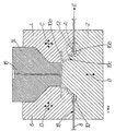
- an inner mould tool 2 and a pair of outer mould tools 4 and 6 are mutually arranged with respect to a packaging sheet material 8 in a moulding position such that the packaging sheet material is disposed between the inner mould tool 2 and the outer mould tools 4 and 6, and such that a mould cavity 10 is formed by the mould tools in which the edge 12 of a hole provided in the sheet 8 is arranged.
- the mould tools are also arranged with respect to a thermoplastics injection head 14 so that heated thermoplastics material may be fed through a channel 16 of the head 14 into the mould cavity 10 in order to form, upon cooling of the heated thermoplastics material, an opening device connected to the sheet 8 at the hole edge 12.
- the packaging sheet material 8 may be of any type and shape.
- sheet 8 may be a continuous web of packaging material, or a blank of packaging material, or a protruding flap of packaging material.
- sheet 8 is a synthetic plastics coated paper carrier material.
- the mould cavity 10 includes in the embodiment shown a portion 10a for forming a lid portion of the opening device, a portion 10b for forming a base portion of the opening device for connection to the sheet 8, and a portion 10c for forming a reduced thickness tearing edge of the opening device for aiding in releasing the lid portion from the base portion.
- the present disclosure relates more in particular to the manner in which the opening device is attached to the sheet 8 at the hole edge 12 thereof, while the opening device may assume any number of different overall shapes,
- the hole edge 12 is circumferential to completely enclose the hole in the sheet 8, and preferably the entire hole edge 12 is arranged inside the base portion 10b of the mould cavity 10 prior to injection, the base portion 10b also being circumferential and having a dimension sufficient to completely enclose hole edge 12.
- the hole edge 12, the base portion 10b, and the connecting portion 10c are ovular ringshaped in a longitudinal cross section extending substantially parallel to the extension of the sheet, and the lid portion 10a is ovular disc-shaped in a longitudinal cross section extending substantially parallel to the extension of the sheet.
- a gap 18 is formed between the mould tools which preferably has a width dimension smaller than the thickness of the packaging sheet material 8 thereby to compress the sheet 8 inside the gap and form a seal sufficient to prevent any significant leakage of the heated thermoplastics material outside of the mould cavity 10.
- the moulding position of Fig 1 may be obtained in any number of ways as will be apparent to those skilled in the art.
- the inner mould 2 may be moved up and down vertically in the direction of arrow B, and the outer moulds 4 and 6 may be moved up and down vertically, and inwardly and outwardly horizontally, according to the directions C and D respectively, while the injection head 14 may remain in essentially a fixed position.
- the packaging sheet material may be intermittently fed in direction E into a correct position with the hole edge 12 properly aligned, whereupon the mould tools may be moved into their fully closed position corresponding to the moulding position of Fig.
- thermoplastics material may be fed through the channel 16 of the injection head 14 for filling the mould cavity 10 and forming the opening device on the sheet. Release of the mould tools will permit the sheet 8 to again be fed in the direction E, so as to arrange another hole edge 12 in proper position for receiving an opening device. Downstream after the opening devices are provided on the sheet, packaging containers from the sheet may be formed, filled with product, and sealed. Methods and apparatus sufficient for feeding the sheet 8, for stamping the holes in the sheet 12, for moving the mould tools, for injecting the heated thermoplastics materials, and for forming, filling and sealing the packaging containers are within the realm of those skilled in the art.
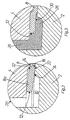
- Fig. 2 shows a moulding configuration 20 of the inner and outer mould tools corresponding to the moulding position of Fig. 1.
- the inner mould tool 2 is arranged in contact with an inner side 22 of sheet 8 while the outer mould tool 4 is arranged in contact with an outer side 24 of the sheet 8.
- the moulding configuration 20 of the outer and inner mould tools biases the portion of the packaging sheet material 8 arranged adjacent the hole edge 12 away from the inner mould tool 2.
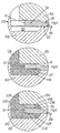
- heated thermoplastics material may be injected into the mould cavity 10 to form an opening device 26 attached to the hole edge 12 of the sheet 8 (Fig. 3).
- the biasing of the sheet 8 away from the inner mould tool assures that a plastics material portion 28 is formed on a portion 30 of the inner side 22 of the sheet 8 arranged adjacent the hole edge 12.
- the biasing of the sheet 8 in the mould cavity 10 and the positive formation of the plastics material portion 28 provides a uniformity and assuredness with regard to the correct positioning of the sheet 8 with respect to the opening device 26, since the sheet is held in a correct and biased position during the step of injection.
- the formation of the plastics material portion 28 at the portion 30 of the inner sheet side near the hole edge 12 efficiently creates an excellent seal at the hole edge and at the inner sheet side, which advantageously aids in assuring that products will not come into contact with the inner layers of the material sheet when the inner side of the packaging sheet material is destined to be a food contact surface in the final packaging container.
- the moulding configuration 20 of the inner mould tool 2 and outer mould tool 4 includes an edge of the outer mould tool 4 which makes contact with the outer side 24 of the packaging sheet material 8 at a first contact line 32, and an edge of the inner mould tool 2 which makes contact with the inner side 22 of the packaging sheet material 8 at a second contact line 34, such that the first contact line 32 is arranged farther from the hole edge 12 than the second contact line 34.
- Fig. 2 shows that in the moulding position, the moulding configuration 20 of the inner and outer mould tools is such that the hole edge 12 of the sheet 8 essentially makes contact with the outer mould tool 4.
- plastics material is not formed on the outer side 24 of the sheet 8, as seen in Fig. 3. It is however possible to shape the outer mould tool 4 so that the hole edge 12 does not make contact with the outer mould tool 4 even after the sheet portion 8a has been biased away from the lower mould tool 2.
- the opening device formed by the thermoplastics injection step will include plastics material portions covering both the inner and outer surfaces of the sheet adjacent the hole edge.
- FIG 3 also shows a small plastics material portion of the opening device 26 arranged in the gap 18 between the inner mould tool 2 and the inner side 22 of the sheet 8 and formed during the generally high pressure injection step.
- the compression of the sheet 8 in the gap 18 is however sufficient to form a seal sufficient to prevent any significant leakage of the heated thermoplastics material outside of the mould cavity 10 through the gap 18.
- the particular mutual relative spacing of the contact lines for determining the extent and direction of bending of the sheet portion 8a, and the particular configuration of the mould cavity formed by the mould tools with respect to the hole edge of the sheet for determining where plastics material portions will be formed will dictate the particular position of the sheet portion 8a in the cavity in the moulding position, so as to assure that the desired final connection and positioning of the opening device to the sheet will be effectively and efficiently obtained.
- Fig. 4 illustrates a further embodiment of the invention including a moulding configuration 120 of inner and outer mould tools 102 and 104 mutually arranged in the moulding position such that the inner mould tool 102 is arranged in contact with the inner side 22 of sheet 8 while the outer mould tool 104 is arranged in contact with an outer side 24 of the sheet 8 for compressing the sheet 8 in a thinner gap 118 formed between the moulds, and such that the hole edge 12 is arranged in the mould cavity 110 formed by the inner and outer moulds.
- the moulding configuration 120 of the outer and inner mould tools 102 and 104 also biases the portion 8a of the packaging sheet material 8 arranged adjacent the hole edge 12 away from the inner mould tool 102.
- thermoplastics material may be injected into the mould cavity 110 to form an opening device 126 attached to the hole edge 12 of the sheet 8 (Fig. 5).
- the biasing of the sheet portion 8a away from the inner mould tool assures that a plastics material portion 128 is formed on a portion 30 of the inner side 22 of the sheet portion 8a arranged adjacent the hole edge 12.
- the biasing of the sheet portion 8a in the mould cavity 110 and the positive formation of the plastics material portion 128 provides a uniformity and assuredness with regard to the correct positioning of the sheet 8 with respect to the opening device 126, since the sheet is held in a correct and biased position during the step of injection, and the formation of the plastics material portion 128 at the portion 30 of the inner sheet side near the hole edge 12 efficiently creates an excellent seal at the hole edge and at the inner sheet side for aiding assuring that products will not come into contact with the inner layers of the material sheet when the inner side of the packaging sheet material is destined to be a food contact surface in the final packaging container.
- the gap 118 of moulding configuration 120 formed between the inner and outer mould tools 102 and 104 has an extension which lies in a plane extending angularly into the mould cavity in a direction extending away from the inner mould tool 102, so as to bias the sheet portion 8a away from the inner mould tool 102 sufficiently so that the plastics material portion is positively formed at the sheet inner side portion 30.
- the contact lines at which the edges of the inner and outer mould tools make contact with the inner and outer surfaces of the sheet 8 are arranged substantially mutually opposite and therefore a bending of the sheet portion 8a with respect to the extension of the gap 118 does not occur.
- Fig. 4 shows that the hole edge 12 of the sheet 8 is slightly spaced with respect to the upper mould tool 104 in the moulding position. This slight spacing however still provides that heated thermoplastics material entering into the mould cavity 110 during the injection phase will push the sheet portion 8a into contact with the outer mould tool so that plastics material is not formed at the upper side of the sheet 8, if so desired.
- Fig. 6 shows a variation of the embodiment of Figs. 4-5 in which a moulding configuration 220 formed by an inner mould tool 202 and an outer mould tool 204 includes an angularly extending gap 218 for biasing the sheet portion 8a in a mould cavity 210 away from the inner mould tool 202, and a spacing between the sheet portion 8a and the outer mould tool 204 which is sufficiently large such that after the thermoplastics injection phase an opening device 226 is formed which includes both a plastics material portion 236 arranged at the outer side 238 of the sheet portion 8a and a plastics material portion 228 arranged at the inner side 230 of the sheet portion 8a.
- Figs. 4-6 shows the sheet portion 8a being biased away from the inner mould tool
- the particular extension of the moulding configuration gap for determining the direction of extension of the sheet portion, and the particular configuration of the mould cavity formed by the mould tools with respect to the hole edge of the sheet for determining where plastics material portions will be formed will dictate the particular position of the sheet portion in the cavity in the moulding position, so as to assure that the desired final connection and positioning of the opening device to the sheet will be effectively and efficiently obtained.
Landscapes
- Engineering & Computer Science (AREA)
- Manufacturing & Machinery (AREA)
- Mechanical Engineering (AREA)
- Injection Moulding Of Plastics Or The Like (AREA)
- Moulds For Moulding Plastics Or The Like (AREA)
- Casting Or Compression Moulding Of Plastics Or The Like (AREA)
- Wrappers (AREA)
Description
Claims (5)
- A method of injection moulding a plastics material part in a hole which is disposed in a packaging sheet material (8) and which defines a hole edge (12) of the packaging sheet material (8), comprising the steps of:characterized in that it comprises the step of arranging the first and second mould tools (2,4,6,102,104,202,204) such that the portion of the packaging sheet material (8) in contact with both the first and second mould tools (2,4,6, 102,104,202,204) is in a compressed state with respect to the portion of the packing sheet material (8) arranged inside the mould cavity (10, 110,210).arranging at least one first mould tool (4,6,104,202) in contact with a first side (24) of the packaging sheet material (8) and arranging at least one second mould tool (2, 102,204) in contact with a second side (22) of the packaging sheet material (8) and thereby forming a mould cavity (10,110,210) defined between said first and second mould tools (2,4,6,102,104,202,204) in a manner such that at least a portion of said hole edge (12) is arranged inside said mould cavity (10,110,210) and such that a sheet portion (8a) of the packaging sheet material (8) arranged adjacent said portion of said hole edge (12) is biased away from said second mould tool (2,102,204); andinjecting plastics material into said mould cavity (10,110,210) so as to form said plastics material part (26) whereby the biasing of said sheet portion (8a) away from said second mould tool (2,202,204) aids in the formation of plastics material (26) on a portion of said second side (22) of the sheet portion (8a);
- The method of claim 1, wherein the forming of said mould cavity (10,110,210) comprises the steps of;characterized in that it comprises the step of arranging said first contact line (32) farther from said portion of said hole edge (12) than said second contact line (34) so as to bias the sheet portion away from said second mould tool (2,102,204).moving said first mould tool (4,6,104,202) such that an edge of said first mould tool makes contact with said first side (24), of the packaging sheet material at a first contact line (32);moving said second mould tool (2) such that an edge of said second mould tool makes contact with said second side (22) of the packaging sheet material (8) at a second contact line (34);
- An injection moulding apparatus for injection moulding a plastics material part in a hole, disposed in a packaging sheet material (8) having a first side (22) and a second side (24), and which defines a hole edge (12) of the packaging sheet material (8), said apparatus comprising a first mould tool (4,6,104,202) and a second (102,202,204) mould tool which are mutually arrangeable with respect to the packaging sheet material (8) in a moulding position such that the packaging sheet material (8) is sealingly disposed between the first and second mould tools (2,4,6,102,104,202,204) and such that a mould cavity (10,110,210) is formed by the first and second mould tools (2,4,6,102,104,202,204) in which at least a portion of the hole edge (12) of the packaging sheet material (8) is arranged, wherein the first and second mould tools (2,4,6,102,104,202,204) have a moulding configuration in the moulding position such that a sheet portion (8a) of the packaging sheet material (8) arranged adjacent said portion of said hole edge (12) is biased away from said second mould tool (102,202,204), whereby to aid in the formation of plastics material on a portion of a second side (24) of the sheet portion (8a), and wherein a gap (18,118,218) is formed between the first and second mould tools (2,4,6,102,104,202,204) in said moulding position, for sealingly accommodating the packaging sheet material (8), characterized in that said gap (18,118,218) has a width dimension which is smaller than a thickness of the packaging sheet material (8), whereby to compress the packaging sheet material (8) in said gap (18,118,218) in the moulding position.
- The injection moulding apparatus according to claim 3, wherein an edge of said first mould tool (4,6,104,202) makes contact with said first side (22) of the packaging sheet material (8) at a first contact line (32), and an edge of the second mould tool (102,202,204) makes contact with said second side (24) of the packaging sheet material (8) at a second contact line (34), characterized in that said first contact line (32) is arranged farther from said portion of said hole edge (12) than said second contact line (34), for biasing the sheet portion (8a) away from said second mould tool (102,202,204).
- The injection moulding apparatus according to claim 3, characterized in that said gap (18,118,218) has an extension which lies in a plane extending angularly into the mould cavity (10,110,210) in a direction extending away from the second mould tool (102,202,204).
Applications Claiming Priority (3)
| Application Number | Priority Date | Filing Date | Title |
|---|---|---|---|
| ITMI962271 | 1996-10-31 | ||
| IT96MI002271A IT1287126B1 (en) | 1996-10-31 | 1996-10-31 | PROCEDURE AND MOLD TOOLS FOR INJECTION MOLDING OF A PART OF PLASTIC MATERIAL IN A PACKAGING SHEET MATERIAL |
| PCT/SE1997/001596 WO1998018609A1 (en) | 1996-10-31 | 1997-09-23 | Method and mould tools for injection moulding a plastics material part in a packaging sheet material |
Publications (2)
| Publication Number | Publication Date |
|---|---|
| EP0935522A1 EP0935522A1 (en) | 1999-08-18 |
| EP0935522B1 true EP0935522B1 (en) | 2002-06-05 |
Family
ID=11375134
Family Applications (1)
| Application Number | Title | Priority Date | Filing Date |
|---|---|---|---|
| EP97943263A Expired - Lifetime EP0935522B1 (en) | 1996-10-31 | 1997-09-23 | Method and mould tools for injection moulding a plastics material part in a packaging sheet material |
Country Status (22)
| Country | Link |
|---|---|
| US (1) | US6251325B1 (en) |
| EP (1) | EP0935522B1 (en) |
| JP (1) | JP3989024B2 (en) |
| KR (1) | KR100364376B1 (en) |
| CN (1) | CN1101306C (en) |
| AR (1) | AR008518A1 (en) |
| AT (1) | ATE218424T1 (en) |
| AU (1) | AU718228B2 (en) |
| BR (1) | BR9712615A (en) |
| CA (1) | CA2270467C (en) |
| DE (1) | DE69713127T2 (en) |
| DK (1) | DK0935522T3 (en) |
| ES (1) | ES2178005T3 (en) |
| FI (1) | FI114300B (en) |
| HU (1) | HU222203B1 (en) |
| IT (1) | IT1287126B1 (en) |
| NO (1) | NO314171B1 (en) |
| PL (1) | PL184640B1 (en) |
| RU (1) | RU2199439C2 (en) |
| TR (1) | TR199900931T2 (en) |
| UA (1) | UA66348C2 (en) |
| WO (1) | WO1998018609A1 (en) |
Families Citing this family (17)
| Publication number | Priority date | Publication date | Assignee | Title |
|---|---|---|---|---|
| GB2330791B (en) | 1997-10-30 | 2002-05-08 | Boucherie Nv G B | Method of molding toothbrushes and apparatus for performing the method |
| SE521876C2 (en) * | 1999-12-22 | 2003-12-16 | Tetra Laval Holdings & Finance | Multi-stage unit for processing a web-shaped packaging material in a food packaging machine |
| US6467238B1 (en) * | 2000-06-15 | 2002-10-22 | Tetra Laval Holdings & Finance, Sa | Direct injection molded closure and method therefor |
| EP1170217B1 (en) | 2000-07-07 | 2003-06-11 | Tetra Laval Holdings & Finance S.A. | Unit for processing a web of packaging material for producing sealed packages of pourable food products |
| SE523936C2 (en) * | 2001-12-19 | 2004-06-01 | Tetra Laval Holdings & Finance | Injection molding tools and methods of injection molding |
| US7059466B2 (en) | 2004-01-23 | 2006-06-13 | Tetra Laval Holdings & Finance, Sa | Carton transfer unit |
| US7313895B2 (en) | 2004-07-20 | 2008-01-01 | Tetra Laval Holdings & Finance, Sa | Molding unit for forming direct injection molded closures |
| DE602006014083D1 (en) | 2006-01-27 | 2010-06-17 | Tetra Laval Holdings & Finance | Method and device for attaching opening devices to packages for liquid food |
| SE0702568L (en) | 2007-11-21 | 2008-09-16 | Tetra Laval Holdings & Finance | Device for reshaping material web |
| EP2347880A1 (en) * | 2010-01-25 | 2011-07-27 | Koninklijke Philips Electronics N.V. | A method for producing a device comprising at least one displaceable operating member as well as such a device |
| US8591792B2 (en) * | 2010-12-28 | 2013-11-26 | Kojima Press Industry Co., Ltd. | Method of molding a first resin member on a second resin member |
| DE102011108156A1 (en) * | 2011-07-20 | 2013-01-24 | Daimler Ag | Connection structure for a motor vehicle and method for its production |
| IL238861A (en) * | 2015-05-17 | 2017-10-31 | Katzin Asaf | Apparatus and method of forming connector brackets for irrigation laterals along an already made lay-flat pipe |
| NL2019232B1 (en) * | 2017-07-11 | 2019-01-28 | Pixsweet B V | Confection package |
| JP7353045B2 (en) * | 2019-03-11 | 2023-09-29 | 藤森工業株式会社 | Container and its manufacturing method |
| US20220063158A1 (en) * | 2020-08-21 | 2022-03-03 | Plastipak Packaging, Inc. | Multi-layer nozzle, method, and articles made therefrom |
| WO2023237402A1 (en) * | 2022-06-06 | 2023-12-14 | Tetra Laval Holdings & Finance S.A. | Molding tool, molding apparatus having a molding tool and packaging machine having a molding apparatus |
Family Cites Families (12)
| Publication number | Priority date | Publication date | Assignee | Title |
|---|---|---|---|---|
| US2821764A (en) * | 1954-03-11 | 1958-02-04 | United Shoe Machinery Corp | Plastic grommets and a method for forming them |
| GB1023886A (en) * | 1963-09-25 | 1966-03-30 | Metal Containers Ltd | Method of and mould for forming a bushing in an opening in a sheet material wall,and sheet material wall produced by said method |
| SE370203B (en) * | 1972-12-18 | 1974-10-07 | Cerbo Ab | |
| US4244491A (en) * | 1977-12-15 | 1981-01-13 | Tokan Kogyo Co., Ltd. | Container cover member having synthetic resin openable portion |
| GB8523263D0 (en) * | 1985-09-20 | 1985-10-23 | Metal Box Plc | Making metal can ends |
| DE3606280A1 (en) * | 1986-02-27 | 1987-09-03 | Altstaedter Verpack Vertrieb | LOCKING DEVICE FOR A SYRINGE DEVICE |
| SU1391917A1 (en) * | 1986-06-06 | 1988-04-30 | Московское Научно-Производственное Объединение По Механизированному Строительному Инструменту И Отделочным Машинам | Method and mould for making metal-reinforced plastic articles with a hole |
| GB2198385B (en) * | 1986-12-05 | 1990-02-07 | Metal Box Plc | Apparatus for injection moulding |
| US4956139A (en) * | 1987-10-06 | 1990-09-11 | Canon Denshi Kabushiki Kaisha | Method of producing an exposure blade |
| SE462743B (en) | 1988-12-16 | 1990-08-27 | Profor Ab | SETTING TO JOIN A GRIP ORGAN WITH A SHEET OR TRAFFIC PACKAGING LAMINATE |
| CN1066037A (en) * | 1991-04-22 | 1992-11-11 | 天龙化学工业株式会社 | The lid arrangement of large container |
| IT1264851B1 (en) * | 1993-06-18 | 1996-10-17 | Facchinetti Annamaria | MOLD FOR FORMING EYELETS AND EYELET |
-
1996
- 1996-10-31 IT IT96MI002271A patent/IT1287126B1/en active IP Right Grant
-
1997
- 1997-09-23 AU AU44777/97A patent/AU718228B2/en not_active Ceased
- 1997-09-23 ES ES97943263T patent/ES2178005T3/en not_active Expired - Lifetime
- 1997-09-23 RU RU99111779/12A patent/RU2199439C2/en not_active IP Right Cessation
- 1997-09-23 UA UA99042441A patent/UA66348C2/en unknown
- 1997-09-23 BR BR9712615-2A patent/BR9712615A/en not_active IP Right Cessation
- 1997-09-23 PL PL97333142A patent/PL184640B1/en unknown
- 1997-09-23 AT AT97943263T patent/ATE218424T1/en active
- 1997-09-23 EP EP97943263A patent/EP0935522B1/en not_active Expired - Lifetime
- 1997-09-23 KR KR1019997003861A patent/KR100364376B1/en not_active Expired - Fee Related
- 1997-09-23 JP JP52034698A patent/JP3989024B2/en not_active Expired - Lifetime
- 1997-09-23 DE DE69713127T patent/DE69713127T2/en not_active Expired - Lifetime
- 1997-09-23 DK DK97943263T patent/DK0935522T3/en active
- 1997-09-23 CA CA002270467A patent/CA2270467C/en not_active Expired - Fee Related
- 1997-09-23 TR TR1999/00931T patent/TR199900931T2/en unknown
- 1997-09-23 WO PCT/SE1997/001596 patent/WO1998018609A1/en not_active Ceased
- 1997-09-23 CN CN97199296A patent/CN1101306C/en not_active Expired - Lifetime
- 1997-09-23 US US09/269,505 patent/US6251325B1/en not_active Expired - Lifetime
- 1997-09-23 HU HU9903853A patent/HU222203B1/en not_active IP Right Cessation
- 1997-10-31 AR ARP970105092A patent/AR008518A1/en active IP Right Grant
-
1999
- 1999-04-29 FI FI990979A patent/FI114300B/en not_active IP Right Cessation
- 1999-04-30 NO NO19992115A patent/NO314171B1/en not_active IP Right Cessation
Also Published As
Similar Documents
| Publication | Publication Date | Title |
|---|---|---|
| EP0935522B1 (en) | Method and mould tools for injection moulding a plastics material part in a packaging sheet material | |
| EP0949992B1 (en) | Apparatus and method for moulding an opening device on a packaging sheet | |
| EP2508432B1 (en) | Packaging container manufacturing method, spout stopper, and packaging container | |
| US12076958B2 (en) | Manufacturing process for producing hermetic single-use food containers such as coffee pods, including a creasing step | |
| US11518076B2 (en) | Molding apparatus configured to injection mold an opening device on a sheet of packaging material | |
| EP3898201B1 (en) | Manufacturing process for producing hermetic single-use food containers using a sealing head having a specific profile with a rib | |
| JP2870341B2 (en) | Method for producing a plug having gas barrier properties | |
| MXPA99003905A (en) | Method and mould tools for injection moulding a plastics material part in a packaging sheet material | |
| HK1024664B (en) | Method and injection moulding apparatus for injection moulding a plastics material part in a hole of a packaging sheet material | |
| JPH0446820B2 (en) | ||
| US20080063745A1 (en) | Thermowelding Station for Producing Thermoformable and Thermoweldable Containers | |
| JPS6228308A (en) | Method of sealing vessel | |
| HK1178223A (en) | Apparatus and method for injection molding opening devices on sheet packaging material for packaging pourable food products |
Legal Events
| Date | Code | Title | Description |
|---|---|---|---|
| PUAI | Public reference made under article 153(3) epc to a published international application that has entered the european phase |
Free format text: ORIGINAL CODE: 0009012 |
|
| 17P | Request for examination filed |
Effective date: 19990531 |
|
| AK | Designated contracting states |
Kind code of ref document: A1 Designated state(s): AT CH DE DK ES FR GB IT LI NL SE |
|
| 17Q | First examination report despatched |
Effective date: 20000705 |
|
| GRAG | Despatch of communication of intention to grant |
Free format text: ORIGINAL CODE: EPIDOS AGRA |
|
| GRAG | Despatch of communication of intention to grant |
Free format text: ORIGINAL CODE: EPIDOS AGRA |
|
| GRAH | Despatch of communication of intention to grant a patent |
Free format text: ORIGINAL CODE: EPIDOS IGRA |
|
| GRAH | Despatch of communication of intention to grant a patent |
Free format text: ORIGINAL CODE: EPIDOS IGRA |
|
| GRAA | (expected) grant |
Free format text: ORIGINAL CODE: 0009210 |
|
| AK | Designated contracting states |
Kind code of ref document: B1 Designated state(s): AT CH DE DK ES FR GB IT LI NL SE |
|
| REF | Corresponds to: |
Ref document number: 218424 Country of ref document: AT Date of ref document: 20020615 Kind code of ref document: T |
|
| REG | Reference to a national code |
Ref country code: GB Ref legal event code: FG4D |
|
| REG | Reference to a national code |
Ref country code: CH Ref legal event code: EP |
|
| REF | Corresponds to: |
Ref document number: 69713127 Country of ref document: DE Date of ref document: 20020711 |
|
| REG | Reference to a national code |
Ref country code: CH Ref legal event code: NV Representative=s name: A. BRAUN, BRAUN, HERITIER, ESCHMANN AG PATENTANWAE |
|
| REG | Reference to a national code |
Ref country code: DK Ref legal event code: T3 |
|
| ET | Fr: translation filed | ||
| REG | Reference to a national code |
Ref country code: ES Ref legal event code: FG2A Ref document number: 2178005 Country of ref document: ES Kind code of ref document: T3 |
|
| PLBE | No opposition filed within time limit |
Free format text: ORIGINAL CODE: 0009261 |
|
| STAA | Information on the status of an ep patent application or granted ep patent |
Free format text: STATUS: NO OPPOSITION FILED WITHIN TIME LIMIT |
|
| 26N | No opposition filed |
Effective date: 20030306 |
|
| REG | Reference to a national code |
Ref country code: CH Ref legal event code: PFA Owner name: TETRA LAVAL HOLDINGS & FINANCE SA Free format text: TETRA LAVAL HOLDINGS & FINANCE SA#70, AVENUE GENERAL-GUISAN, P.O. BOX 430#1009 PULLY (CH) -TRANSFER TO- TETRA LAVAL HOLDINGS & FINANCE SA#70, AVENUE GENERAL-GUISAN, P.O. BOX 430#1009 PULLY (CH) |
|
| REG | Reference to a national code |
Ref country code: CH Ref legal event code: PCAR Free format text: NEW ADDRESS: HOLBEINSTRASSE 36-38, 4051 BASEL (CH) |
|
| PGFP | Annual fee paid to national office [announced via postgrant information from national office to epo] |
Ref country code: DK Payment date: 20140910 Year of fee payment: 18 |
|
| PGFP | Annual fee paid to national office [announced via postgrant information from national office to epo] |
Ref country code: GB Payment date: 20140917 Year of fee payment: 18 Ref country code: AT Payment date: 20140827 Year of fee payment: 18 |
|
| PGFP | Annual fee paid to national office [announced via postgrant information from national office to epo] |
Ref country code: ES Payment date: 20150810 Year of fee payment: 19 Ref country code: CH Payment date: 20150911 Year of fee payment: 19 |
|
| PGFP | Annual fee paid to national office [announced via postgrant information from national office to epo] |
Ref country code: SE Payment date: 20150911 Year of fee payment: 19 |
|
| PGFP | Annual fee paid to national office [announced via postgrant information from national office to epo] |
Ref country code: NL Payment date: 20150909 Year of fee payment: 19 |
|
| REG | Reference to a national code |
Ref country code: DK Ref legal event code: EBP Effective date: 20150930 |
|
| REG | Reference to a national code |
Ref country code: AT Ref legal event code: MM01 Ref document number: 218424 Country of ref document: AT Kind code of ref document: T Effective date: 20150923 |
|
| GBPC | Gb: european patent ceased through non-payment of renewal fee |
Effective date: 20150923 |
|
| PG25 | Lapsed in a contracting state [announced via postgrant information from national office to epo] |
Ref country code: GB Free format text: LAPSE BECAUSE OF NON-PAYMENT OF DUE FEES Effective date: 20150923 |
|
| REG | Reference to a national code |
Ref country code: FR Ref legal event code: PLFP Year of fee payment: 20 |
|
| PG25 | Lapsed in a contracting state [announced via postgrant information from national office to epo] |
Ref country code: AT Free format text: LAPSE BECAUSE OF NON-PAYMENT OF DUE FEES Effective date: 20150923 |
|
| PG25 | Lapsed in a contracting state [announced via postgrant information from national office to epo] |
Ref country code: DK Free format text: LAPSE BECAUSE OF NON-PAYMENT OF DUE FEES Effective date: 20150930 |
|
| PGFP | Annual fee paid to national office [announced via postgrant information from national office to epo] |
Ref country code: IT Payment date: 20160921 Year of fee payment: 20 Ref country code: DE Payment date: 20160920 Year of fee payment: 20 |
|
| PGFP | Annual fee paid to national office [announced via postgrant information from national office to epo] |
Ref country code: FR Payment date: 20160816 Year of fee payment: 20 |
|
| PG25 | Lapsed in a contracting state [announced via postgrant information from national office to epo] |
Ref country code: SE Free format text: LAPSE BECAUSE OF NON-PAYMENT OF DUE FEES Effective date: 20160924 |
|
| REG | Reference to a national code |
Ref country code: CH Ref legal event code: PL |
|
| REG | Reference to a national code |
Ref country code: SE Ref legal event code: EUG |
|
| REG | Reference to a national code |
Ref country code: NL Ref legal event code: MM Effective date: 20161001 |
|
| PG25 | Lapsed in a contracting state [announced via postgrant information from national office to epo] |
Ref country code: NL Free format text: LAPSE BECAUSE OF NON-PAYMENT OF DUE FEES Effective date: 20161001 |
|
| PG25 | Lapsed in a contracting state [announced via postgrant information from national office to epo] |
Ref country code: CH Free format text: LAPSE BECAUSE OF NON-PAYMENT OF DUE FEES Effective date: 20160930 Ref country code: LI Free format text: LAPSE BECAUSE OF NON-PAYMENT OF DUE FEES Effective date: 20160930 |
|
| REG | Reference to a national code |
Ref country code: DE Ref legal event code: R071 Ref document number: 69713127 Country of ref document: DE |
|
| REG | Reference to a national code |
Ref country code: ES Ref legal event code: FD2A Effective date: 20180507 |
|
| PG25 | Lapsed in a contracting state [announced via postgrant information from national office to epo] |
Ref country code: ES Free format text: LAPSE BECAUSE OF NON-PAYMENT OF DUE FEES Effective date: 20160924 |