JP4634653B2 - Direct injection molded closure and method therefor - Google Patents
Direct injection molded closure and method therefor Download PDFInfo
- Publication number
- JP4634653B2 JP4634653B2 JP2001180340A JP2001180340A JP4634653B2 JP 4634653 B2 JP4634653 B2 JP 4634653B2 JP 2001180340 A JP2001180340 A JP 2001180340A JP 2001180340 A JP2001180340 A JP 2001180340A JP 4634653 B2 JP4634653 B2 JP 4634653B2
- Authority
- JP
- Japan
- Prior art keywords
- molding tool
- carton
- closure
- molding
- tool
- Prior art date
- Legal status (The legal status is an assumption and is not a legal conclusion. Google has not performed a legal analysis and makes no representation as to the accuracy of the status listed.)
- Expired - Fee Related
Links
Images


Classifications
-
- B—PERFORMING OPERATIONS; TRANSPORTING
- B65—CONVEYING; PACKING; STORING; HANDLING THIN OR FILAMENTARY MATERIAL
- B65B—MACHINES, APPARATUS OR DEVICES FOR, OR METHODS OF, PACKAGING ARTICLES OR MATERIALS; UNPACKING
- B65B61/00—Auxiliary devices, not otherwise provided for, for operating on sheets, blanks, webs, binding material, containers or packages
- B65B61/18—Auxiliary devices, not otherwise provided for, for operating on sheets, blanks, webs, binding material, containers or packages for making package-opening or unpacking elements
- B65B61/186—Auxiliary devices, not otherwise provided for, for operating on sheets, blanks, webs, binding material, containers or packages for making package-opening or unpacking elements by applying or incorporating rigid fittings, e.g. discharge spouts
-
- B—PERFORMING OPERATIONS; TRANSPORTING
- B29—WORKING OF PLASTICS; WORKING OF SUBSTANCES IN A PLASTIC STATE IN GENERAL
- B29C—SHAPING OR JOINING OF PLASTICS; SHAPING OF MATERIAL IN A PLASTIC STATE, NOT OTHERWISE PROVIDED FOR; AFTER-TREATMENT OF THE SHAPED PRODUCTS, e.g. REPAIRING
- B29C45/00—Injection moulding, i.e. forcing the required volume of moulding material through a nozzle into a closed mould; Apparatus therefor
- B29C45/14—Injection moulding, i.e. forcing the required volume of moulding material through a nozzle into a closed mould; Apparatus therefor incorporating preformed parts or layers, e.g. injection moulding around inserts or for coating articles
- B29C45/14336—Coating a portion of the article, e.g. the edge of the article
-
- B—PERFORMING OPERATIONS; TRANSPORTING
- B65—CONVEYING; PACKING; STORING; HANDLING THIN OR FILAMENTARY MATERIAL
- B65B—MACHINES, APPARATUS OR DEVICES FOR, OR METHODS OF, PACKAGING ARTICLES OR MATERIALS; UNPACKING
- B65B3/00—Packaging plastic material, semiliquids, liquids or mixed solids and liquids, in individual containers or receptacles, e.g. bags, sacks, boxes, cartons, cans, or jars
- B65B3/02—Machines characterised by the incorporation of means for making the containers or receptacles
- B65B3/025—Making parallelepipedal containers from a single carton blank
-
- B—PERFORMING OPERATIONS; TRANSPORTING
- B29—WORKING OF PLASTICS; WORKING OF SUBSTANCES IN A PLASTIC STATE IN GENERAL
- B29C—SHAPING OR JOINING OF PLASTICS; SHAPING OF MATERIAL IN A PLASTIC STATE, NOT OTHERWISE PROVIDED FOR; AFTER-TREATMENT OF THE SHAPED PRODUCTS, e.g. REPAIRING
- B29C45/00—Injection moulding, i.e. forcing the required volume of moulding material through a nozzle into a closed mould; Apparatus therefor
- B29C45/14—Injection moulding, i.e. forcing the required volume of moulding material through a nozzle into a closed mould; Apparatus therefor incorporating preformed parts or layers, e.g. injection moulding around inserts or for coating articles
- B29C45/14336—Coating a portion of the article, e.g. the edge of the article
- B29C45/14344—Moulding in or through a hole in the article, e.g. outsert moulding
-
- B—PERFORMING OPERATIONS; TRANSPORTING
- B29—WORKING OF PLASTICS; WORKING OF SUBSTANCES IN A PLASTIC STATE IN GENERAL
- B29L—INDEXING SCHEME ASSOCIATED WITH SUBCLASS B29C, RELATING TO PARTICULAR ARTICLES
- B29L2031/00—Other particular articles
- B29L2031/712—Containers; Packaging elements or accessories, Packages
- B29L2031/7162—Boxes, cartons, cases
-
- Y—GENERAL TAGGING OF NEW TECHNOLOGICAL DEVELOPMENTS; GENERAL TAGGING OF CROSS-SECTIONAL TECHNOLOGIES SPANNING OVER SEVERAL SECTIONS OF THE IPC; TECHNICAL SUBJECTS COVERED BY FORMER USPC CROSS-REFERENCE ART COLLECTIONS [XRACs] AND DIGESTS
- Y10—TECHNICAL SUBJECTS COVERED BY FORMER USPC
- Y10S—TECHNICAL SUBJECTS COVERED BY FORMER USPC CROSS-REFERENCE ART COLLECTIONS [XRACs] AND DIGESTS
- Y10S493/00—Manufacturing container or tube from paper; or other manufacturing from a sheet or web
- Y10S493/916—Pliable container
- Y10S493/927—Reclosable
- Y10S493/929—Reclosable with valve
Description
【0001】
【発明の属する技術分野】
本発明は、容器用の成型したクロージャ(ふた)に関する。より詳細には、クロージャを容器上に直接射出成型することに関する。
【0002】
【従来の技術】
消費者は、液体の食料製品などを貯蔵する容器用の再封止可能なクロージャを認識し、評価するようになってきている。これらの再封止可能なクロージャは、容易に食品を入手できるようにする一方で、容器を再封止する能力を提供して、製品の寿命と新鮮さを延長する。通常、1つまたは複数のポリマ・コーティングあるいはポリマ層を有する厚紙材料の合成物で容器またはカートン(紙箱)を形成し、液体が浸透しない構造を確立する。
【0003】
そのようなクロージャを有する既知の容器では、クロージャは、別々の工程で形成されて包装工程に搬送され、従来、全体の形成充填封止操作の一部として容器に取り付けられる。通常、部分的に立ち上げられたカートンにクロージャを取り付け、その後カートンに製品をつめる。クロージャをカートンに取り付ける1つの既知の方法は、超音波溶接工程を使用する。この方法では、カートンを部分的に立ち上げ、クロージャをカートンに接触させて、カートンの開口と重なるようにする。その後、アンビル(金床)をカートンの材料に接触させて配置し、超音波ホーンがクロージャのフランジと接触するようにする。超音波でフランジをカートンの材料に溶接する超音波ホーンを起動する。
【0004】
クロージャをカートンに取り付ける他の方法は、誘導加熱工程を使用する。この方法では、再び、アンビルをカートンの材料上に配置し、誘導封止ヘッドをフランジと接触させる。誘導封止ヘッドに電流を誘導し、再び、フランジをカートンに溶接する。
【0005】
【発明が解決しようとする課題】
クロージャをカートンに取り付けるこれらの方法は、予め形成または予め成型したクロージャを容器に封止するにはよく機能し、製品の新鮮さと容器の再封止可能性の維持を容易にするが、やはり欠点がある。例えば、クロージャの部品を外注することは、製品の製造に重大な逆効果を及ぼすことがある。すなわち、瓶詰め業者または乳製品業者は、大量のクロージャの在庫を維持して、瓶詰め操作中に確実に十分な量が手近にあるようにしなければならない。通常、クロージャは、クロージャの製造業者または納入業者によって提供される。したがって、製造業者または納入業者が、要求された供給量に応じることができない場合、必要な量のクロージャを獲得することができるまで、製品の製造(包装など)が減速または停止する可能性がある。
【0006】
さらに、クロージャを搬送し、カートンに取り付ける設備が必要である。この設備については、貯蔵場所からカートンまでキャップを輸送し、おそらくは、適切にクロージャをカートンに向ける構成要素が必要である。また、カートンでクロージャを支え、クロージャをカートンに封止するために、追加の機械構成要素が必要である。
【0007】
したがって、容易に認識されるように、そのようなクロージャは、既知の折り畳んだゲーブル(切妻屋根形)トップ注ぎ口の構成に対し、多くの利益と利点をもたらすが、これらのクロージャはかなり高価なことがあり、より高価でない製品に使用するには価格が高すぎる可能性がある。
【0008】
したがって、カートン上に再封止可能なクロージャを提供する装置および方法が必要である。そのような装置および方法により、クロージャの納入業者に対する包装業者の依存が解消されることが好ましい。そのような装置および方法は、溶接などによって、クロージャをカートンに取り付けることに関係する形成充填包装機械の部分をなくすことを見込んでいることがより好ましい。
【0009】
【課題を解決するための手段】
カートンを形成、充填、および封止する形成充填封止包装機械は、直接クロージャをカートン上に成型する。この機械は、全体として平坦な形態でカートンを受け取り、平坦な形態のカートンを、内部カートン領域を画定する管状形態に立ち上げるように構成されているカートン立ち上げステーションを含む。
【0010】
直接射出成型ステーションは、内部成型ツールと外部成型ツールを有する。好ましい実施形態では、内部ツールは固定して取り付けられ、外部ツールは、外部ツールが内部ツールから外れる第1位置と、内部ツールと係合する第2位置との間で動くように構成されており、2つのツールの間にカートンが配置される。最も好ましい実施形態では、外部ツールは、外部ツールが第2位置に向かって動くとき、互いに近づき、外部ツールが第1位置に向かって動くとき、互いから離れるように構成されている第1部分および第2部分を有して形成される。
【0011】
内部成型ツールは、内部カートン領域内に入るように構成されている。内部成型ツールと外部成型ツールは、その間でカートンを受け取り、クランプするように構成されている。
【0012】
直接射出成型ステーションは、さらに、カートンの外部の位置から、内部成型ツールにポリマを射出するポリマ射出システムを含み、したがって、カートン上の適切な位置にクロージャを直接成型する。
【0013】
この機械は、さらに、カートンを充填する充填ステーションと、カートンに封をする封止ステーションを有する。
【0014】
ポリマ射出システムは、互いに直列である装填シリンダと射出シリンダを含むように構成することができる。装填シリンダは、射出シリンダにポリマを供給する。装填シリンダと射出シリンダが互いに対向する関係にあり、逆止め弁によって分離されていることが最も好ましい。
【0015】
好ましい実施形態では、機械は、射出シリンダと流れ連通しているスプルー(湯口)ブッシュと、内部ツールへのポリマの流れを開始および終了するためにスプルー・ブッシュ内で往復運動可能な針を含む。
【0016】
形成中にツールとクロージャの適切な温度管理を実施するために、内部成型ツールと外部成型ツールは、冷却チャネル(溝)を含む。熱の移動は、V型の形態の冷却チャネルを備える内部ツールにおいて最大になる。
【0017】
この機械では、フレームを包装機械に取り付けることが可能であり、マンドレルがフレームに取り付けられており、その上にカートンが取り付けられ、クロージャの成型中に、成型ツールによって固定される。内部成型ツールがマンドレルに取り付けられていることが好ましい。
【0018】
管状の形態にあるカートンのブランク(半加工品)上にクロージャを形成する方法であって、カートン・ブランクが、その少なくとも1つの側面上にポリマ層を有する複合材料から形成されている方法は、内部に成型空洞の部分を画定する固定成型ツールを準備し、成型ツールが、ポリマ射出システムと流れ連通している段階と、内部ツールと隣接および係合してカートン・ブランクを配置し、カートン・ブランクが、管状形態を有する少なくとも部分的に立ち上げられた状態にある段階と、内部に成型空洞の他の部分を画定する可動ツールを準備し、固定ツール・成型空洞と可動ツール・成型空洞が、所望のクロージャの構成を画定する段階とを含む。
【0019】
さらに、この方法は、内部ツールとは反対側で、可動ツールをカートン・ブランクに係合させる段階と、可動ツールをカートン・ブランクと固定ツールに押し付ける段階と、ポリマを成型空洞に射出し、好ましいクロージャを形成する段階と、クロージャを成型したカートンを解放する段階とを含む。
【0020】
本発明の他の特徴と利点は、以下の詳細な記述、添付の図面、および請求項から明らかになるであろう。
【0021】
【発明の実施の形態】
本発明は、様々な形態の実施形態が可能であるが、本開示は、本発明の例と見なすべきであり、本発明を示した特定の実施形態に限定するものではないとの理解の下に、現在の好ましい実施形態を図面に示し、以下に記述する。
【0022】
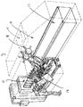
図面、特に図1を参照すると、本発明の原理を具体化する、直接射出成型クロージャ・ステーション12を含む、形成充填封止機械10が示されている。通常の形成充填封止機械10では、様々なステーションが機械10に沿って配置され、カートンの立ち上げ、カートンの底面パネルの折畳みと封止、殺菌、製品の充填、および上面パネルの折畳みと上面フラップの封止を実施する。1つのそのような機械は、Katsumata氏の米国特許第6,012,267号に開示されている。この特許は、本願と同じ譲受人に譲渡されており、参考に本明細書に援用する。充填ステーション11、殺菌システム15、および封止ステーション17を図1に示す。
【0023】
直接射出成型ステーション12(以下では「DIMC」ステーションと呼ぶ)は、カートン・マガジン/立ち上げステーション14とカートン・ローダ(積み込み機)16の間に位置する。しかし、当業者によって認識されるように、ステーション12は機械に沿って様々な位置に配置することができ、全ての位置が本発明の範囲内にある。
【0024】
ここで、図3から図14を参照すると、本発明によるDIMCステーション12の成型構成要素の1つの実施形態が示されている。上述したように、この実施形態では、DIMCステーション12は、カートン・マガジン/立ち上げステーション14とカートン・ローダ16の間に位置し、カートン・ローダは、さらに、組み立てたカートンCを、充填機械10の底面形成マンドレル18に運ぶ。
【0025】
DIMCステーション12は、フレーム20、ポリマ射出システム22、針24、およびスプルー・ブッシュ26を含む。ステーション12は、さらに、内部ツールまたは成型28、マンドレル30、マンドレル30に取り付けられたマンドレル・キャップ32、外部ツール34a,b、および押付け機構36を含む。
【0026】
フレーム20は、構造に提供されており、システムの構成要素を機械10に取り付けるために設けられている。フレーム20は、カートンCの上面Tを配置するマンドレル30と、内部ツールまたは成型28を受け取り、支持するように構成されたポケットまたはチャネル38と、スプルー・ブッシュ26用の角度をつけた通路40と、冷却剤チャネル42とを支持する。冷却剤は、冷却剤供給(図示せず)から、成型ツール28および34a,bに供給される。
【0027】
ポリマ射出システム22は、ペレットPの形態など固体状態のポリマを受け取り、そのポリマを融解して、クロージャ・成型ツール28および34a,bに搬送するDIMCステーション12の部分である。図4から図14に示す、企図したポリマ射出システム22は、シリンダ52に配置されている、スクリュー形式のコンベヤまたは押出し機50を含む。未加工ポリマPは、スクリュー・シリンダ52の上流端でホッパ54に供給される。スクリュー50は回転し、シリンダ52の周囲に配置された加熱要素56は、ポリマの温度を上昇させる。好ましい実施形態では、加熱要素56は電気で稼動する。
【0028】
スクリュー50によって加えられるねじれの力と、加熱要素56によって伝達されるエネルギーにより、ポリマは融解する。スクリュー・シリンダ52の出口端58で、融解したばかりのポリマは、伝達導管57、逆止め弁好ましくはチェック弁59を通って、加圧空間62を有する装填シリンダ60内に流れ込む。
【0029】
装填シリンダ60は、往復運動する装填ピストン64を含む。装填ピストン64は、射出シリンダ68と対向する関係にあり、それと流れ連通している。逆止め弁好ましくはチェック弁70は、装填シリンダ60の出口で、装填シリンダ60と射出シリンダ68の間に配置されている。チェック弁70により、装填シリンダ60から射出シリンダ68にポリマが流れることが可能になるが、逆の流れ(すなわち、射出シリンダ68から装填シリンダ60)は防止する。
【0030】
射出シリンダ68の縦軸Aiは、ほぼ、装填シリンダ60の縦軸Acと整合した向きを向いている。すなわち、例示の射出システム22では、射出シリンダ68と装填シリンダ60は、互いに対向しているかまたは対向した関係にある。以下で記述するように、この構成は、射出システム22の低操作圧力と併せて、クロージャSを容器材料またはカートンC上に直線に直接成型することを可能にする。
【0031】
72で矢印によって示すように、装填ピストン64の圧縮ストローク(すなわち射出ストローク)は、融解したポリマを射出シリンダ68内に押し込む。同様に、74で矢印によって示すように、射出ピストン73の圧縮ストロークは、融解したポリマを、射出シリンダ68から射出出口導管76と制御弁78を通して押し出す。図8と図9を参照すると、DIMCステーション12の現在の実施形態では、射出出口導管76は、スプルー・ブッシュ26と流れ連通して、スプルー・ブッシュ26の一部として形成されており、針24は、スプルー・ブッシュ26内で往復運動または運動し、制御弁78として機能する。
【0032】
図14を参照すると、装填ピストン64は、動作可能なように装填ピストン64に接続されている副次ないし駆動ピストン/シリンダ構成84によって起動される。また、射出ピストン73は、副次ないし駆動ピストン/シリンダ構成(操作ピストン/シリンダ構成)84によって起動される。操作シリンダ86は、射出ピストン73のストロークを妨げるストップ88を含む。この構成により、射出シリンダ68から放出される、融解ポリマの量を精密に制御することが可能になる。
【0033】
上記に述べたように、このシステム22は、低圧を使用して、射出シリンダ68から成型空洞44に、融解ポリマを移動または放出する。そのような低圧のシステムは、既知の高圧射出システムに対して多くの利点を提供する。例えば、本低圧システムにより、射出成型技術によって、クロージャSを直接厚紙カートンC上に成型することが可能になる。これは、以前には、従来の高圧射出成型システムでは実行不可能であると見なされていた。上述したシステムに類似の低圧射出成型システムは、1997年4月3日に公表された、国際出願PCT/SE96/01191(WO97/11829)に開示されている。本実施形態では、射出圧力は、約600バールから約1000バールであり、約800バールであることが好ましい。この直接成型の応用例に使用可能なポリマは、低密度のポリエチレン(LDPE)および線形低密度のポリエチレン(LLDPE)など、食品に使用することが承認されている様々な任意の材料を含む。融解ポリマの好ましい操作温度は、約200℃であり、成型ツール28および34a,bの好ましい操作温度は、約25℃である。
【0034】
ポリマ射出システム22の操作では、ペレットPは、ホッパ54に供給され、スクリュー・シリンダ52内へ供給される。スクリュー50が回転して、加熱要素56によって、熱形態のエネルギーがシリンダ52に伝達され、ポリマが融解する。ポリマはスクリュー・シリンダ52を出て、チェック弁59を通って装填シリンダ60の加圧空間62内へ流れる。融解したポリマは、射出ピストン73の圧縮ストロークまたは射出ストーク74中に一時的に加圧空間62に保存され、その間、チェック弁59は、射出シリンダ68の圧力が増大した結果として閉鎖している。さらに、射出ピストン73の圧縮ストローク74中に、装填ピストン64は、非圧縮位置に戻る。これにより、装填シリンダ60の圧力はより低くなり、チェック弁59が開いて、ポリマが、スクリュー・シリンダ52から装填シリンダ60内へ流れることが可能になる。
【0035】
射出ピストン73が非射出(すなわち非圧縮)位置に戻ると、装填ピストン64は、加圧空間62から射出シリンダ68に材料を移動する。装填シリンダ60の増大した圧力のためにチェック弁59が閉じ、スクリュー・シリンダ52内hへの逆流を防止する。射出ピストン73が圧縮ストロークまたは射出ストローク74を経て動くとき、装填ピストン64は、非装填(非圧縮)位置に戻る。このようにして、スクリュー50は、連続的に回転して、融解したポリマを前方に押し、ポリマは、射出ピストン73の圧縮(射出)ストローク74中に、装填シリンダ60の加圧空間62に一時的に保存される。この構成により、停滞領域など、射出システム22内のデッド・スポットは低減ないし除去される。
【0036】
本射出システム22は、本質的に、3つの圧力領域を画定する。第1に、ほぼ一定圧力の領域を、ほぼチェック弁59までのスクリュー・シリンダ52によって画定する。第2に、やはりほぼ一定圧力の領域を、装填シリンダ60、装填ピストン64、およびチェック弁59と70によって画定する。第3圧力領域は、可変(高)圧力領域であり、針24を通り過ぎて成型空洞44までおよび成型空洞44を含んで、射出シリンダ68と射出ピストン73、チェック弁70とスプルー・ブッシュ26を通る流れ経路によって画定される。
【0037】
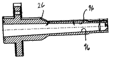
針24は、スプルー・ブッシュ26内に配置されており、成型空洞44内に流れるポリマ流を制御する働きをする。針24は、スプルー・ブッシュ26内で往復運動し、内部成型ツール28上で、台座75から離れて上昇する。針24は、ポリマの温度を制御する内部加熱器90を含み、ポリマが成型空洞44に射出されるときに、流動状態に維持する。上記に述べたように、スプルー・ブッシュ26は、射出シリンダ68から成型空洞44まで、流れ導管を提供する。図10と図11を参照すると、スプルー・ブッシュ26は、葉形(lobe)内部通路92を有するように形成されている。ローブは、スプルー・ブッシュ26の中心にある針24を維持する中心スパイン(尾根)を画定する。本実施形態では、葉形通路92とスパイン93は、スプルー・ブッシュ26のほぼ終末端部に形成されている。また、この構成により、成型空洞44に流れるポリマの制御が強化される。本実施形態では、スプルー・ブッシュ26は、葉形が3つである通路92を有する。内部通路の他の構成は、本発明の範囲内にある。
【0038】
内部ツール28と外部ツール34a,bは、(カートンに対して)成型空洞44の内側および外側の表面を形成する。内部ツールまたは雄ツール28は、スプルー・ブッシュ26と同様に静止しており、スプルー・ブッシュ26への封止接続部を設けられている。内部ツール28は、図示したネジ付きボルトなど、複数のファスナ(締着具)94によって、マンドレル30に剛性的に取り付けられている。図10からわかるように、スプルー・ブッシュ26は、葉形通路92の他に、96で示すように、針24用の整合経路を提供する、内向に先細りになっている表面を含む。さらに、内部ツール28は、スプルー・ブッシュ26を受けるボア(孔)98と、融解したポリマが空洞44に流れ込むゲート100を含む。冷却チャネル102が、内部ツール28に形成されており、ポリマが空洞44に射出され、クロージャSを形成した後、ツールとポリマを冷却する。本実施形態では、図13b,cに示すように、内部ツール28にある冷却チャネル102は、V型の流れチャネルまたは流れ経路104を画定するように形成される。この構成は、高熱伝達率および大きな熱伝達領域を提供して、比較的小さく限定された領域での熱伝達の増大に備える。
【0039】
外部ツールまたは雌ツール34a,bの対を使用して、カートンCを内部ツール28に対して圧縮する。外部ツール34a,bを押付け機構36に取り付け、この圧縮を提供する。押付け機構36は、外部ツール34a,bの2方向の運動に備えている。一方の運動方向は、内部ツール28に向かいそしてそれから離れるものである。他方の運動方向は、外部ツール半体34aと34bを互いに近づけ離すように動かす。外部ツール34a,bが互いに押し付けられ、内部ツール28に押し付けられているとき、ツール28および34a,bは、ポリマが射出される成型空洞44を形成する。DIMCステーション12の本実施形態では、押付け機構36は、約2.270キログラム(約5000ポンド)から約3.178キログラム(約7000ポンド)の圧力を内部ツール28と外部ツール34a,bの間に加える。当業者には認識されるように、これは、10から15トンという高さであることがあり得る既知の射出成型システムで必要な圧力よりかなり小さい。
【0040】
2方向の運動は、成型したクロージャSから外部ツール34a,bを引き出すまたは離れるように動かすことができ(カートンCから離れる第1方向)、成型ツール28および34a,bからクロージャを解放することができるように提供される。2個の外部ツールの2つのセクション34aと34bは、成型後、成型した部分を損傷せずに、互いに分離して、クロージャSの解放を容易にする。
【0041】
内部ツール28と同様に、外部ツール34a,bは、ポリマの射出中そしてその後に、ツール34a,bに冷却剤を提供する冷却チャネル106を含む。また、外部ツール34a,bは、押付け機構36にツール34a,bを取り付ける取付けホール110を含む。外部ツール34a,bを取り付けることと、互いに対するおよび内部ツール28に対する外部ツール34a,bの運動については、国際出願PCT/SE97/01594(WO98/18608)およびPCT/SE97/01596(WO98/18609)により完全に議論されている。
【0042】
内部ツール28は、マンドレル30に取り付けられている。マンドレル30は、支持部材であり、その上に、クロージャSの形成中にカートンCが装填される。マンドレル30は、剛性的にフレーム20に取り付けられているか、またはフレーム20の一部として形成され、ポリマの射出によって誘起された液圧力に対抗して内部ツール28を支持する。内部ツール28および外部ツール34a,bは、適切にツール28と34a,bをそれぞれの支持部材に取り付けるために使用する取付けホール110、112と、適切にツール28と34a,bを互いに対して位置合わせするために使用する、位置合わせ開口114とを含む。
【0043】
機械10のセット・アップ中に、外部ツール34a,bは、ネジ付きボルト116などによって、押付け機構36に取り付けられる。外部ツール34a,bは、「閉鎖した」状態で配置されているが、これは、ツール28および34a,bがポリマの射出に対して準備ができている状態である。内部ツール28が外部ツール34a,b上に設定されているので、位置合わせピン118は、内部ツール開口114を通して、外部ツール34a,b内に挿入される。このようにして、ツール28および34a,bは、適切なクロージャSの成型のために設定または位置合わせされる。
【0044】
フレーム20の部分は、内部ツール28が、ツール28を受けるマンドレル・キャップ32に形成されているチャネルまたはポケット38と位置合わせされるまで、機械10のフレームに配置されている。次いで、内部ツール28は、ネジ付きボルト120などによって、マンドレル・キャップ32に固定され、フレーム20は、機械10のフレーム固定される。次いで、位置合わせピン118を除去して、外部ツール34a,bが自由に動くことができるようにする。
【0045】
図8と図9からわかるように、本DIMCステーション12では、ポリマは、カートンCの内部から成型空洞44に射出される。すなわち、カートンCが、内部ツール28と外部ツール34a,bの間に適切な上面がある状態で配置され、押付け機構36が閉鎖しているとき、スプルー・ブッシュ26と内部ツール・ゲート100の境界面は、カートンCに対して内部である位置にある。これは、カートンCの向きが水平方向であることによって可能になる。このようにして、ポリマの流れ経路は、クロージャSの内部部分からクロージャSの外部部分に向かう。本質的に、成型は、組み立てたカートンの内部領域から行われる。
【0046】
この構成は、いくつかの利点を提供し、そのような利点の1つは、あらゆるゲートの痕跡または成型操作から残留した付着しているポリマ(一般に、ポリマを成型空洞内に誘導したところのポリマの部分)は、消費者には見えず、代わりに、容器の内部にあるということである。通常この痕跡は、美的に設計された箇所ではなく、成型工程の残留物なので、この配置はパッケージの全体的な外観を向上する。したがって、クロージャの内部部分にゲートの痕跡を形成するということは、それを普通は消費者が見ることのない領域に位置させるということである。
【0047】
この構成の他の利点は、スプルー・ブッシュ26が、静止内部ツール28に接合することである。したがって、ポリマを成型空洞44に送達するシステム22のその部分は、静止している。これにより、内部ツール28(およびシステム22のポリマ送達部分)を動かす必要がなく、したがって、ツール28および34a,bの不整合が少なくなる。
【0048】
図と本記述を読んで当業者には認識されるように、ポリマは、直線的に、装填シリンダ60と射出シリンダ68の間を流れ、放出後は、射出シリンダ68からゲート100を経て成型空洞44内に(すなわち、スプルー・ブッシュ26とゲート100を経て内部ツール28内に)流れる。この直線的な構成により、射出システム22のデッド・スポットが除去され、結果的にポリマの品質をより低下させないことになる。
【0049】
さらに、マンドレル30とマンドレル・キャップ32は、カートンCの内側と密接して嵌合し、成型ツール28および34a,bに関して、正確な射出位置(カートンの上面パネルまたはフラップ上)を導いて精密に定めるように構成されている。この構成は、成型28と34a,bの間にカートンCを正確に配置する(±0.5mm)ことを保証し、これにより、開口などに存在する可能性がある包装材料の被覆していない縁部を密閉することができる。
【0050】
当業者には認識されるように、従来のクロージャの応用技術では、カートンCは予めパンチした或いは予め形成した開口を備えており、クロージャは、その中にはめ込まれ、続いてカートンに封止されている。この領域の周囲の縁部は、カートン材料の複合構造またはラミネート構造の製造後に開口が形成されるので、被覆されていない。
【0051】
そのような予め形成した開口を有するカートンをDIMCステーション12と共に使用することが予測されるが、予め形成されていない材料を使用することが可能であることと、直接射出成型工程の一部またはそれと一体化して、開口を形成することができることも予測されることである。このために、本方法では、クロージャSを直接カートンC上に成型し、一方、カートンCの被覆されていない開口の縁部Eを密閉する。これにより、カートンCの外観は向上し、被覆していない縁部Eを密閉して露出しない結果として、衛生状態を改善することになる。また、正確にカートンCをマンドレル30の上に配置することにより、包装材料によりツール28および34a,bを損傷する可能性が大いに低減し或いはなくなる。
【0052】
位置合わせピン118を使用して、ツール28および34a,bを整合させる本構成により、内部ツール28と外部ツール34a,bに、非常に小さい許容度を用いることが可能になる。さらに、位置合わせピン118は、ツール28および34a,bが静止しているときに配置され、互いに位置決めされた後にのみ除去されるので、ツール28および34a,bの正確な位置合わせが簡単になる。これにより、クロージャSの質と成型位置の正確さが向上し、さらに、操作中におけるツール28および34a,bを損傷が防止される。
【0053】
スプルー・ブッシュ26と内部ツール28の間の密閉接続部は、122で示すように、シリンダの表面上にあり、スプルー・ブッシュ26の端に対して軸線方向隙間を有する。このために、内部ツール28に応力を加えることなくに、融解したポリマは収容され、スプルー・ブッシュ26の熱膨張に対応する。
【0054】
本ステーションは、コンパクトな冷却チャネル102と106の構成を使用する。これは、内部ツール28の位置合わせホール114と共に、内部ツール28の大きさを最小限に抑える。内部ツール28の大きさを最小限に抑えることにより、マンドレル30の断面の慣性モーメントが最大になり、したがってその剛性を増大する。マンドレル30の剛性は、クロージャSの断面の薄いの厚みを制御するために重要であり、この薄い厚みは、当業者には認識されるように、クロージャSの機能にとって重要である。例えば、(以下で記述するように)クロージャが薄膜またはもろい部材で成型されている場合、もろい部材の厚さ(または薄さ)は、破損が確実に正確な所定の位置で生じるように、厳密に制御されなければならない。また、いたずら即発見の特徴を含めて、クロージャの他の部分についても、同様のことがあてはまる。
【0055】
上述したように、内部ツール28は、V型の冷却チャネル102を含む。これは、内部ツール28からの熱の除去を最大にし、その結果サイクルの時間が短縮され、さらに、現在の形成充填封止包装機械の高速操作に応じるために必要な、成型したクロージャSの高い処理能力を支持する。
【0056】
企図した方法では、カートンCのブランクは、カートン・マガジン14から供給される。カートンCは、この形態では、側部に封をされ、上面と底面のパネルは、封止されておらず、平坦に折り畳まれている。カートンCをマガジン14から取り上げ、(図3に示すように、マンドレル30上に載せて)管状の形態に組み立てる。図1と図2を参照すると、管状形態のカートンCは、コンベヤ・ローダ130の上に配置され、コンベヤ132に移送される。コンベヤ132は、カートンCをDIMCステーション12に移動させる。モールダ・ローダ134は、カートンCをコンベヤ132からステーション12に移送する。管状のカートンCは、DIMCステーション12上で水平方向を向いており(すなわち、側面を下にして)、マンドレル30上に配置されている。押付け機構36は、外部ツール34a,bを互いに対して、そして内部ツール28に対して閉鎖し、必要な負荷または圧力を与えて、ポリマの射出中に成形型が閉鎖されているようにする。
【0057】
射出システム22は、操作時にはほぼ一定であり、次いで、射出ピストン73の圧縮ストローク74によって起動され、融解ポリマは、スプルー・ブッシュ26を通り、針24を通過して、射出シリンダ68から射出される。これにより、針24は、強制的に内部ツール28の台座75から離れて上昇し、融解ポリマは成型空洞44を満たす。カートンCにある開口Oの縁部Eは、融解ポリマが成型空洞44を満たす際に、密閉される。また、これにより、融解ポリマは包装材料の重合被覆に結合される。
【0058】
冷却チャネル102と106を通って流れる冷却剤は、クロージャSを冷却し、ツール28および34a,bを所定の温度範囲内に維持する。次いで、押付け機構36が開き、外部ツール34aと34bを分離して、それらを内部ツール28から引き離す。次いで、完成したクロージャSを成形型から解放する。カートンCは成型したクロージャSを有し、マンドレル30から解放され、コンベヤ136上に置かれる。コンベヤ136はカートンを搬送して、シャトル138に配置する。シャトル138は、底面パネルを折り畳んで封止するために、カートンCをマンドレル・ローダ140に供給する。工程のこの部分(底面形成マンドレル上に配置し、底面パネルを折り畳んで封止する)は、当技術分野ではよく知られている。底面パネルの封止に続いて、カートンCは、形成充填封止機械10の残りの部分を通って移動する。
【0059】
図15は、操作の単一サイクルにおいて、DIMCステーション12を操作して、クロージャSを4つのカートンC上に形成する、1つの構成である。この構成では、カートンC1からC4は、それぞれのマガジン14からコンベヤ132上にのせられる。コンベヤ132は、カートンC1からC4を、4つのDIMCステーション12−1から12−4の1つに搬送する。クロージャSをカートンC1からC4上に成型し、上述したように、カートンをシャトル138−1から138−4に搬送して、さらに処理する。
【0060】
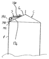
本発明により形成された企図したクロージャSを、図16から図18に示す。
図からわかるように、クロージャSは、底面フランジ部分176と、直立スパウト(注ぎ口)178を含む。クロージャSのキャップ部分180は、フランジ176と一体化しており、かつフランジ176から分離可能に形成される。このクロージャSでは、突起182が、キャップ180から後方に延び、フランジ176の後方から上方に延びるポスト184と係合するように構成されている。後方突起182は、ポスト184と係合し、解放位置にあるキャップ180を固定するフック状の端186を含むことが好ましい。ポスト184は、上方および後方に延びて、突起182によってより大きな「積極的な」係合をもたらすことができる。
【0061】
図17中の拡大図からわかるように、フランジ部分176は、クロージャSが形成されている開口Oの縁部Eで、材料を囲んで密閉する。これは、クロージャSとカートンCの間に、一体性が高く、信頼性の高い封止を提供して有利である。さらに、開口Oの縁部Eは被覆されていないので、これらの縁部Eを密閉することにより、液体がカートンの材料内へ浸入し或いは毛管作用により流出する機会を低減または排除する。浸入または毛管作用による流出を低減するということは、これにより、カートン/クロージャの組合わせが製品の質に影響をもたらす際に、その一体性が強化されるという点で、望ましいことである。また、この密閉構成により、製品の質を向上し、カートンの一体性を損ないおよび/または製品を汚染する機会を低減することによって、再び、製品の貯蔵寿命を改善することが予測される。
【0062】
さらに、クロージャSは、全体を188で示す、いたずら即発見部分を含む。これは、除去または転置されたときに、包装の密封が壊された可能性があることを消費者に示すものである。本構成では、いたずら即発見部分188は、キャップ180と一体状に形成されてカートンCの材料へ延びているタブ190を含む。図18からわかるように、タブ190の端192もカートンCに成型されていることが好ましく、フランジ176から間隔を置いて配置されているカートンCに成型されていることが最も好ましい。このようにして、カートンCの中身を利用する(すなわち、キャップ180を開く)ために、カートンCに成型されているタブ190の部分192を引くか取り除くことが必要である。タブ190は、端192がカートンCから離れるように形成することができる。これに代えて、好ましくは、タブの端192とキャップ180の間に配置されたもろい部分194を有するタブ190を、もろい領域194でタブ190を壊し、キャップ180を開いて、カートンCの中身を入手するように構成することができる。図19に示したカートンCでわかるように、タブ190は、カートンCのゲーブル部分Gから前面壁Fまでに及び、この状態で張力を受けている。これにより、さらに、いたずらを即発見しまたはそれを示すことができるようになる。
【0063】
キャップ180は、細長蝶番196の回りに旋回して、キャップ180の開閉に関連する応力を低減するように構成されている。また、キャップ180は、198で示すように、例えば、包装製造者、乳製品業者、瓶詰め業者などを示す表示(図示せず)を含むように、比較的平坦な上面領域を含むことができる。
【0064】
以上より、本発明の新規な概念の精神および範囲から逸脱せずに、多くの修正および変形を実施することができるということが判ろう。図示した特定の実施形態に関して何ら限定は意図しておらず、または推測すべきでないことを理解されたい。この開示は、添付の請求項によって、請求項の範囲内にあるそのような全ての修正を網羅することを意図している。
【図面の簡単な説明】
【図1】本発明の原理を実現する、直接射出成型クロージャ(「DIMC」)部を搭載した形成充填封止包装機械の斜視図である。
【図2】機械の他の部分に対するDIMCセクションの配置を示す、図1の機械の拡大部分斜視図である。
【図3】クロージャを成型するために配置した例示的なカートンと共に成型構成要素を示す、DIMCステーションの成型構成要素の斜視図である。
【図4】図3に示す成型構成要素の分解図である。
【図5】図3と図4の成型構成要素の部分分解図である。
【図6】図3と図4の成型構成要素の部分分解図である。
【図7】図3と図4の成型構成要素の部分分解図である。
【図8】針がスプルー・ブッシュ内に配置され、スプルー・ブッシュが内部成型ツール内に配置されていることを示す、成型構成要素の部分断面図である。
【図9】図8の針とスプルー・ブッシュ、および内部ツールと外部ツールの拡大部分断面図である。
【図10】スプルー・ブッシュの断面図である。
【図11】スプルー・ブッシュの内部図である。
【図12】針の側面図である。
【図13a】スプルー・ブッシュ受け開口と冷却チャネルを形成した内部成型ツールの図である。
【図13b】別の方向から見た図13aの内部成型ツールの図である。
【図13c】別の方向から見た図13aの内部成型ツールの図である。
【図13d】別の方向から見た図13aの内部成型ツールの図である。
【図14】DIMCステーションと共に使用するポリマ射出システムの実施形態の図である。
【図15】単一操作サイクルにおいて、複数のクロージャがそれぞれのカートン上に成型される、DIMCステーションの1つの操作モードの図である。
【図16】本発明により形成された例示的なクロージャの図である。
【図17】本発明により形成された例示的なクロージャの図である。
【図18】本発明による例示的なクロージャが、形成、充填、および封止されたカートン上に形成されていることを示す図である。
【符号の説明】
10 形成充填封止機械
11 充填ステーション
12 直接射出成型クロージャ・ステーション
14 カートン・マガジン/立ち上げステーション
17 封止ステーション
18 マンドレル
20 フレーム
22 ポリマ射出システム
24 針
26 スプルー・ブッシュ
28 内部成型ツール
30 マンドレル
32 マンドレル・キャップ
34a,b 外部成型ツール
36 押付け機構
42 冷却チャネル
44 空洞
50 スクリュー
52 スクリュー・シリンダ
54 ホッパ
60 装填シリンダ
62 加圧空間
64 装填ピストン
68 射出シリンダ
73 射出ピストン
98 ボア
102 冷却チャネル
104 流れ経路
106 冷却チャネル
110 取付けホール
114 位置合わせホール
132 コンベヤ
134 モールダ・ローダ
136 コンベヤ
138 シャトル
140 マンドレル・ローダ
178 直立スパウト
180 キャップ
188 いたずら即発見部分
190 タブ
194 もろい部分[0001]
BACKGROUND OF THE INVENTION
The present invention relates to a molded closure for a container. More particularly, it relates to injection molding a closure directly onto a container.
[0002]
[Prior art]
Consumers are increasingly recognizing and evaluating resealable closures for containers that store liquid food products and the like. These resealable closures make food readily available while providing the ability to reseal the container, extending the life and freshness of the product. Typically, a container or carton is formed from a composite of cardboard material having one or more polymer coatings or polymer layers to establish a structure that is impermeable to liquids.
[0003]
In known containers having such a closure, the closure is formed in a separate process and transported to the packaging process and is conventionally attached to the container as part of the overall forming, filling and sealing operation. Usually, a closure is attached to a partially raised carton, and then the product is packed into the carton. One known method of attaching the closure to the carton uses an ultrasonic welding process. In this method, the carton is partially raised and the closure is brought into contact with the carton so that it overlaps the carton opening. The anvil is then placed in contact with the carton material so that the ultrasonic horn contacts the flange of the closure. Activate an ultrasonic horn that ultrasonically welds the flange to the carton material.
[0004]
Another method of attaching the closure to the carton uses an induction heating process. In this method, again, the anvil is placed on the carton material and the induction sealing head is in contact with the flange. An electric current is induced in the induction sealing head and again the flange is welded to the carton.
[0005]
[Problems to be solved by the invention]
These methods of attaching the closure to the carton work well for sealing pre-formed or pre-formed closures to the container, facilitating maintenance of product freshness and resealability of the container, but again with drawbacks There is. For example, outsourcing closure parts can have a significant adverse effect on the manufacture of the product. That is, the bottling or dairy company must maintain a large inventory of closures to ensure that a sufficient amount is available during the bottling operation. Typically, the closure is provided by the closure manufacturer or supplier. Thus, if the manufacturer or supplier cannot meet the required supply, product manufacturing (such as packaging) may slow down or stop until the required amount of closure can be obtained. .
[0006]
In addition, equipment is needed to transport the closure and attach it to the carton. For this facility, a component is needed to transport the cap from the storage location to the carton and possibly properly point the closure to the carton. Also, additional mechanical components are required to support the closure with the carton and seal the closure to the carton.
[0007]
Thus, as will be readily appreciated, such closures provide many benefits and advantages over known folded gable (gable roof) top spout configurations, but these closures are rather expensive. And may be too expensive to use for less expensive products.
[0008]
Accordingly, there is a need for an apparatus and method that provides a resealable closure on a carton. Such an apparatus and method preferably eliminates the packer's dependence on closure suppliers. More preferably, such an apparatus and method allows for the elimination of the portion of the form-fill-wrap machine involved in attaching the closure to the carton, such as by welding.
[0009]
[Means for Solving the Problems]
A forming, filling, and sealing machine that forms, fills, and seals the carton directly molds the closure onto the carton. The machine includes a carton launch station configured to receive a carton in a generally flat form and to launch the flat form carton into a tubular form defining an interior carton region.
[0010]
The direct injection molding station has an internal molding tool and an external molding tool. In a preferred embodiment, the internal tool is fixedly attached and the external tool is configured to move between a first position where the external tool is disengaged from the internal tool and a second position where it engages the internal tool. A carton is placed between the two tools. In a most preferred embodiment, the external tools are configured to approach each other when the external tools move toward the second position and to move away from each other when the external tools move toward the first position; Formed with a second portion.
[0011]
The internal molding tool is configured to fall within the internal carton area. The internal molding tool and the external molding tool are configured to receive and clamp the carton therebetween.
[0012]
The direct injection molding station further includes a polymer injection system that injects the polymer into the internal molding tool from a location external to the carton, thus directly molding the closure into the appropriate location on the carton.
[0013]
The machine further has a filling station for filling the carton and a sealing station for sealing the carton.
[0014]
The polymer injection system can be configured to include a loading cylinder and an injection cylinder that are in series with each other. The loading cylinder supplies polymer to the injection cylinder. Most preferably, the loading cylinder and the injection cylinder are in opposition to each other and separated by a check valve.
[0015]
In a preferred embodiment, the machine includes a sprue bush that is in flow communication with the injection cylinder and a needle that is reciprocable within the sprue bushing to initiate and terminate polymer flow to the internal tool.
[0016]
In order to implement proper temperature management of the tool and closure during formation, the internal and external molding tools include cooling channels (grooves). Heat transfer is maximized in internal tools with V-shaped form cooling channels.
[0017]
In this machine, the frame can be attached to a packaging machine, a mandrel is attached to the frame, and a carton is attached to it and secured by a molding tool during closure molding. An internal molding tool is preferably attached to the mandrel.
[0018]
A method of forming a closure on a carton blank in a tubular form, wherein the carton blank is formed from a composite material having a polymer layer on at least one side thereof. Providing a stationary molding tool defining a portion of the molding cavity therein, wherein the molding tool is in flow communication with the polymer injection system, and adjacent to and engaging the inner tool to place a carton blank; A blank is provided that is in an at least partially raised state having a tubular form, and a movable tool is provided that defines another portion of the molding cavity therein, the fixed tool / molding cavity and the movable tool / molding cavity comprising Defining a desired closure configuration.
[0019]
Further, the method preferably includes engaging the movable tool with the carton blank on the side opposite the internal tool, pressing the movable tool against the carton blank and the stationary tool, and injecting the polymer into the molding cavity. Forming a closure and releasing the carton molded with the closure.
[0020]
Other features and advantages of the invention will be apparent from the following detailed description, the accompanying drawings, and the claims.
[0021]
DETAILED DESCRIPTION OF THE INVENTION
While the invention is susceptible to various forms of embodiment, it is to be understood that this disclosure is to be regarded as an example of the invention and is not intended to limit the invention to the particular embodiments shown. The presently preferred embodiments are shown in the drawings and are described below.
[0022]
Referring to the drawings, and in particular to FIG. 1, a forming, filling and sealing
[0023]
A direct injection molding station 12 (hereinafter referred to as a “DIMC” station) is located between the carton magazine /
[0024]
Referring now to FIGS. 3-14, one embodiment of the molding component of the
[0025]
The
[0026]
A
[0027]
The
[0028]
The torsional force applied by the
[0029]
The
[0030]
Vertical axis A of injection cylinder 68 i Is approximately the longitudinal axis A of the
[0031]
As indicated by the arrow at 72, the compression stroke (ie, injection stroke) of the
[0032]
Referring to FIG. 14, the
[0033]
As stated above, the
[0034]
In operation of the
[0035]
When the
[0036]
The
[0037]
[0038]
[0039]
The carton C is compressed against the
[0040]
Bi-directional movement can move the
[0041]
Similar to the
[0042]
The
[0043]
During set up of the
[0044]
A portion of the
[0045]
As can be seen from FIGS. 8 and 9, in the
[0046]
This configuration provides several advantages, one of which is the presence of adhering polymer remaining from any gate trace or molding operation (generally the polymer where the polymer is guided into the molding cavity). Part) is invisible to the consumer and instead is inside the container. This arrangement usually improves the overall appearance of the package because this trace is not an aesthetically designed spot, but a residue of the molding process. Thus, forming a trace of the gate in the interior part of the closure means that it is located in an area that is normally not seen by the consumer.
[0047]
Another advantage of this configuration is that
[0048]
As will be appreciated by those skilled in the art upon reading the figures and this description, the polymer flows linearly between the
[0049]
Further, the
[0050]
As will be appreciated by those skilled in the art, in conventional closure applications, the carton C is provided with a pre-punched or pre-formed opening, the closure being fitted therein and subsequently sealed to the carton. ing. The peripheral edge of this region is uncovered since an opening is formed after the manufacture of a composite or laminate structure of carton material.
[0051]
It is anticipated that a carton having such a pre-formed opening will be used with the
[0052]
This configuration of aligning
[0053]
The hermetic connection between the
[0054]
The station uses a
[0055]
As described above, the
[0056]
In the contemplated method, a blank of carton C is supplied from the
[0057]
The
[0058]
The coolant flowing through the cooling
[0059]
FIG. 15 is one configuration in which the
[0060]
A contemplated closure S formed in accordance with the present invention is shown in FIGS.
As can be seen, the closure S includes a
[0061]
As can be seen from the enlarged view in FIG. 17, the
[0062]
Furthermore, the closure S includes a mischievous instant discovery portion, indicated generally at 188. This indicates to the consumer that when removed or displaced, the package seal may have been broken. In this configuration, the
[0063]
The
[0064]
From the foregoing, it will be appreciated that many modifications and variations can be made without departing from the spirit and scope of the novel concepts of the present invention. It should be understood that no limitation with respect to the particular embodiment illustrated is intended or should be inferred. This disclosure is intended to cover all such modifications that fall within the scope of the claims, by the appended claims.
[Brief description of the drawings]
FIG. 1 is a perspective view of a form-fill-seal packaging machine equipped with a direct injection mold closure (“DIMC”) section that implements the principles of the present invention.
FIG. 2 is an enlarged partial perspective view of the machine of FIG. 1 showing the placement of the DIMC section relative to other parts of the machine.
FIG. 3 is a perspective view of a molding component of a DIMC station showing the molding component with an exemplary carton arranged to mold a closure.
4 is an exploded view of the molding component shown in FIG. 3;
5 is a partially exploded view of the molded component of FIGS. 3 and 4. FIG.
6 is a partially exploded view of the molded component of FIGS. 3 and 4. FIG.
7 is a partially exploded view of the molded component of FIGS. 3 and 4. FIG.
FIG. 8 is a partial cross-sectional view of a molding component showing that the needle is disposed within the sprue bushing and the sprue bushing is disposed within the internal molding tool.
9 is an enlarged partial cross-sectional view of the needle and sprue bushing and the internal and external tools of FIG.
FIG. 10 is a cross-sectional view of a sprue bushing.
FIG. 11 is an internal view of a sprue bushing.
FIG. 12 is a side view of a needle.
13a is a view of an internal molding tool with a sprue bushing receiving opening and a cooling channel. FIG.
13b is a view of the internal molding tool of FIG. 13a viewed from another direction.
13c is a view of the internal molding tool of FIG. 13a viewed from another direction.
13d is a view of the internal molding tool of FIG. 13a viewed from another direction.
FIG. 14 is a diagram of an embodiment of a polymer injection system for use with a DIMC station.
FIG. 15 is a diagram of one mode of operation of a DIMC station in which multiple closures are molded on each carton in a single operating cycle.
FIG. 16 is a diagram of an exemplary closure formed in accordance with the present invention.
FIG. 17 is a diagram of an exemplary closure formed in accordance with the present invention.
FIG. 18 illustrates that an exemplary closure according to the present invention is formed on a formed, filled, and sealed carton.
[Explanation of symbols]
10 Forming filling sealing machine
11 Filling station
12 Direct injection molding closure station
14 Carton Magazine / Startup Station
17 Sealing station
18 Mandrel
20 frames
22 Polymer injection system
24 needles
26 Sprue Bush
28 Internal molding tools
30 mandrels
32 Mandrel Cap
34a, b External molding tool
36 Pushing mechanism
42 Cooling channel
44 cavity
50 screw
52 Screw / Cylinder
54 Hopper
60 loading cylinder
62 Pressurized space
64 loading piston
68 Injection cylinder
73 Injection piston
98 bore
102 Cooling channel
104 Flow path
106 Cooling channel
110 Mounting hole
114 alignment hole
132 conveyor
134 Molda Loader
136 conveyor
138 Shuttle
140 Mandrel Loader
178 Upright spout
180 cap
188 Mischievous instant discovery part
190 tabs
194 Fragile part
Claims (10)
フレームと、Frame,
第1成型ツールと第2成型ツールを含む成型ツールセットにして、第1成型ツールが前記フレームに担持され、このフレームに設けた冷却剤を供給する溝に連通して該第1成型ツールに形成した冷却溝を有し、第2成型ツールが第1成型ツールから係合を解く第1位置と、カートンを間に置いて第1成型ツールと係合する第2位置との間で可動であり、第1および第2部分を備えて形成され、これら第1および第2部分は、第2成型ツールが第2位置へ移動すると互いへ向けて動き、第2成型ツールが第2位置へ移動すると互いに離れるように構成した成型ツールセットと、A molding tool set including a first molding tool and a second molding tool is formed, and the first molding tool is supported on the frame and is formed in the first molding tool by communicating with a groove for supplying a coolant provided on the frame. A cooling groove that is movable between a first position where the second molding tool disengages from the first molding tool and a second position where the second molding tool engages the first molding tool with a carton in between. Formed with a first and a second part, which move towards each other when the second molding tool is moved to the second position, and when the second molding tool is moved to the second position. A molding tool set configured to be separated from each other;
カートンの外部の位置から前記成型ツールセットへポリマを提供するポリマ流れ導管を含むポリマ射出システムとを備え、A polymer injection system including a polymer flow conduit for providing polymer from a location external to the carton to the molding tool set;
クロージャが、カートンの所定の部分に直接成型される直接射出成型ステーション。A direct injection molding station where the closure is molded directly into a predetermined part of the carton.
全体として平坦な形態のカートンを受け取り、平坦な形態のカートンを、内部カートン領域を画定する管状形態に立ち上げるようになったカートン立ち上げステーションと、A carton launching station adapted to receive a generally flat form carton and launch the flat form carton into a tubular form defining an interior carton region;
内部成型ツールと外部成型ツールを備えた成型ツールを有する直接射出成型ステーションにして、この内部成型ツールが内部カートン領域内に入るように構成され、これら内部成型ツールと外部成型ツールが、これらツールの間にカートンを受け取って、締めるように構成されており、直接射出成型ステーションがさらに、カートンの外部の位置から前記成型ツールにポリマを射出するポリマ射出システムを含み、クロージャが、カートン上の適切な位置に直接成型され、外部成型ツールが内部成型ツールから係合を解く第1位置と、カートンを間に置いて内部成型ツールと係合する第2位置との間で移動するように構成され、第1および第2部分を備えて形成され、これら第1および第2部分は、外部成型ツールが第2位置へ移動すると互いへ向けて動き、外部成型ツールが第2位置へ移動すると互いに離れるように構成した直接射出成型ステーションと、A direct injection molding station having a molding tool with an internal molding tool and an external molding tool, the internal molding tool is configured to enter the internal carton area, and the internal molding tool and the external molding tool are The direct injection molding station further includes a polymer injection system for injecting the polymer into the molding tool from a location external to the carton, the closure being adapted to an appropriate on the carton. Molded directly into position and configured to move between a first position in which the outer molding tool disengages from the inner molding tool and a second position in which the carton is interposed to engage the inner molding tool; Formed with a first and a second part, which are interchanged when the external molding tool is moved to the second position. Move towards, and direct injection molding station in which the external mold tool configured apart from one another when moved to the second position,
カートンを充填する充填ステーションと、A filling station for filling the carton;
カートンに封をする封止ステーションとを備える形成充填封止包装機械。A forming, filling and sealing packaging machine comprising a sealing station for sealing a carton.
前記フレームによって担持される固定成型ツールにして、前記フレームに形成した冷却剤を供給する溝と流れ連通して該固定成型ツール内に形成した冷却溝を有する固定成型ツールと、A fixed molding tool carried by the frame and having a cooling groove formed in the fixed molding tool in flow communication with a groove for supplying a coolant formed in the frame;
フレームによって担持された可動成型ツールにして、第1および第2部分に形成され、これら第1および第2部分は、可動成型ツールの第1および第2部分が固定成型ツールから係合を解く第1位置と、可動成型ツールの第1および第2部分が間に包装材料を置いて固定成型ツールに係合する第2位置との間で、互いに向けて、また互いから離れるように、そして固定成型ツールに向けて、また固定成型ツールから離れるように可動であり、可動成型ツールの第1および第2部分が、これら第1および第2部分に形成した、固定成型ツールの冷却溝へ冷却剤を供給する冷却溝を有する可動成型ツールとを備え、A movable molding tool carried by the frame is formed in the first and second portions, the first and second portions being first in which the first and second portions of the movable molding tool are disengaged from the stationary molding tool. Between one position and a second position where the first and second parts of the movable molding tool engage the stationary molding tool with the packaging material in between, towards and away from each other and fixed A coolant to the cooling groove of the fixed molding tool, which is movable toward the molding tool and away from the fixed molding tool, wherein the first and second parts of the movable molding tool are formed in the first and second parts. A movable molding tool having a cooling groove for supplying
固定成型ツールと可動成型ツールとを互いに係合すると、クロージャに対応する成型空洞が形成され、固定成型ツールが、冷却剤を該固定成型ツールに供給するための冷却剤源と流れ連通して該固定成型ツール内に形成した冷却溝を有する、成型ツール・セット。Engaging the fixed molding tool and the movable molding tool with each other forms a molding cavity corresponding to the closure, and the stationary molding tool is in flow communication with a coolant source for supplying coolant to the stationary molding tool. Molding tool set with cooling grooves formed in a fixed molding tool.
一体状に包装材料に成型され、接続フランジを形成しているベース部分と、A base part that is integrally molded into a packaging material to form a connection flange;
ベース部分から上方に延びている注ぎ口部分と、A spout portion extending upward from the base portion;
注ぎ口部分に封をするように構成されているカバーと、A cover configured to seal the spout portion;
カバーと一体状に形成されるいたずら即発見部材にして、クロージャを最初に開けた際に壊れるカバーと一体のもろい部材として形成されるいたずら即発見部材とを備え、A mischievous discovery member formed integrally with the cover, and a mischievous discovery member formed as a brittle member integral with the cover that breaks when the closure is first opened,
前記接続フランジは縁部を形成する包装材料の開口において該包装材料に成型され、接続フランジ部分がこの縁部を完全に包む、直接射出成型のクロージャ。A direct injection molded closure in which the connecting flange is molded into the packaging material at the opening of the packaging material forming the edge, and the connecting flange part completely wraps around the edge.
内部に成型空洞の一部分を画定し、ポリマ射出システムと流れ連通している固定成型ツールを準備する段階と、Providing a fixed molding tool defining a portion of the molding cavity therein and in flow communication with the polymer injection system;
管状形態のカートン・ブランクを、該カートン・ブランクが少なくとも部分的に立ち上げられた状態で、固定成型ツールの周りに該固定成型ツールと係合させて配置する段階と、Placing a tubular carton blank in engagement with the fixed molding tool around the fixed molding tool with the carton blank at least partially raised;
内部に成型空洞の他の部分を画定する可動成型ツールを準備し、固定成型ツールの成型空洞と可動成型ツールの成型空洞が、所望のクロージャ形状を画定する段階と、Providing a movable molding tool for defining other portions of the molding cavity therein, wherein the molding cavity of the stationary molding tool and the molding cavity of the movable molding tool define a desired closure shape;
固定成型ツールとは反対側で、可動成型ツールをカートン・ブランクに係合させて成型空洞を形成する段階と、Engaging the movable molding tool with the carton blank to form a molding cavity on the opposite side of the fixed molding tool;
可動成型ツールをカートン・ブランクと固定成型ツールに押し付ける段階と、Pressing the movable molding tool against the carton blank and the fixed molding tool;
ポリマを成型空洞内に射出して、所望のクロージャを形成する段階と、Injecting the polymer into the mold cavity to form the desired closure;
成型空洞からクロージャを解放する段階とを含む方法。Releasing the closure from the mold cavity.
Applications Claiming Priority (2)
| Application Number | Priority Date | Filing Date | Title |
|---|---|---|---|
| US09/594,247 US6467238B1 (en) | 2000-06-15 | 2000-06-15 | Direct injection molded closure and method therefor |
| US594247 | 2000-06-15 |
Publications (3)
| Publication Number | Publication Date |
|---|---|
| JP2002052627A JP2002052627A (en) | 2002-02-19 |
| JP2002052627A5 JP2002052627A5 (en) | 2008-07-31 |
| JP4634653B2 true JP4634653B2 (en) | 2011-02-16 |
Family
ID=24378125
Family Applications (1)
| Application Number | Title | Priority Date | Filing Date |
|---|---|---|---|
| JP2001180340A Expired - Fee Related JP4634653B2 (en) | 2000-06-15 | 2001-06-14 | Direct injection molded closure and method therefor |
Country Status (3)
| Country | Link |
|---|---|
| US (5) | US6467238B1 (en) |
| JP (1) | JP4634653B2 (en) |
| NO (1) | NO323189B1 (en) |
Families Citing this family (34)
| Publication number | Priority date | Publication date | Assignee | Title |
|---|---|---|---|---|
| SE524484C2 (en) * | 2002-01-21 | 2004-08-17 | Tetra Laval Holdings & Finance | Method and apparatus for producing plastic parts |
| SE525597C2 (en) * | 2002-12-06 | 2005-03-15 | Tetra Laval Holdings & Finance | Opening device packaging and ways of providing a package with an opening device |
| US7059466B2 (en) * | 2004-01-23 | 2006-06-13 | Tetra Laval Holdings & Finance, Sa | Carton transfer unit |
| US20050277533A1 (en) * | 2004-06-01 | 2005-12-15 | Franco Pagliari | A method and machine for attomatically and continuously appling a pouring spout on pre-sheared paperboard oval ansd square discs for closing paperboard boxes |
| US7571846B2 (en) * | 2004-07-20 | 2009-08-11 | Tetra Laval Holdings & Finance, S.A. | Carton blank for direct injection molded closures |
| US7313895B2 (en) * | 2004-07-20 | 2008-01-01 | Tetra Laval Holdings & Finance, Sa | Molding unit for forming direct injection molded closures |
| US7500940B2 (en) * | 2004-10-05 | 2009-03-10 | Nimco Corporation | Spout applicator |
| DE102004057164A1 (en) * | 2004-11-26 | 2006-06-01 | Krauss-Maffei Kunststofftechnik Gmbh | injection molding machine |
| US8251242B2 (en) | 2005-06-10 | 2012-08-28 | Pwp Industries | Tamper-evident container with extended band |
| US7631776B2 (en) | 2005-06-10 | 2009-12-15 | Pwp Industries | Tamper evident container with tear-apart parts |
| US8083089B2 (en) | 2005-07-13 | 2011-12-27 | Pwp Industries Inc. | Versatile tamper-evident food container |
| DE202005021060U1 (en) * | 2005-09-14 | 2007-01-18 | Siemens Ag | Injection molding machine, especially for injection stamping, comprises an injection unit with a linear drive unit, a closure unit with a linear drive unit, and a preplastication unit |
| SE529720C2 (en) * | 2006-03-10 | 2007-11-06 | Tetra Laval Holdings & Finance | Method of manufacturing a package |
| US7487007B2 (en) | 2006-10-19 | 2009-02-03 | Husky Injection Molding Systems Ltd. | Overmolding system |
| US8066137B2 (en) | 2007-08-08 | 2011-11-29 | Clear Lam Packaging, Inc. | Flexible, stackable container including a lid and package body folded from a single sheet of film |
| US8231024B2 (en) | 2007-08-08 | 2012-07-31 | Clear Lam Packaging, Inc. | Flexible, stackable container and method and system for manufacturing same |
| US7614202B2 (en) * | 2007-11-27 | 2009-11-10 | Atlas Vac Machine Co., Llc | Sealer and interchangeable tooling therefor |
| US20090206082A1 (en) * | 2008-02-14 | 2009-08-20 | Pwp Industries | Tamper-evident packaging system |
| DE102008002853A1 (en) | 2008-05-14 | 2009-12-03 | Sig Technology Ag | Opening-and effusion element for square shaped beverage package, has hinge line extending between origin and end of effusion element, and formed with opening element using composite material, during opening process |
| EP2376338A4 (en) | 2008-11-06 | 2012-12-26 | Clear Lam Packaging Inc | Flexible, stackable container and method and system for manufacturing same |
| US10220986B2 (en) | 2009-03-06 | 2019-03-05 | Pactiv Corporation | Tamper evident container with full tab |
| JP5486753B2 (en) * | 2009-11-30 | 2014-05-07 | 日本テトラパック株式会社 | Packaging container manufacturing method, spout stopper and packaging container |
| JP5626789B2 (en) * | 2010-12-20 | 2014-11-19 | 日本テトラパック株式会社 | Resealable opening device for paper containers |
| CN103402885A (en) * | 2010-12-30 | 2013-11-20 | 赫尔希公司 | Flexible film container and method for making same |
| AU2013334078B2 (en) | 2012-10-26 | 2018-02-22 | Primapak, Llc | Flexible package and method of making the same |
| US10207850B2 (en) | 2012-10-26 | 2019-02-19 | Primapak, Llc. | Flexible package and method of making same |
| EP3145819B1 (en) | 2014-05-19 | 2020-12-02 | Primapak, LLC | Apparatus and method for making a flexible package |
| CA2998754A1 (en) | 2015-09-18 | 2017-03-23 | Primapak, Llc | Apparatus and method for making a flexible package |
| DE102015012939A1 (en) * | 2015-10-01 | 2017-04-06 | Kocher-Plastik Maschinenbau Gmbh | Method for reducing the microbiological burden on container products |
| US11753204B2 (en) * | 2018-07-04 | 2023-09-12 | Tetra Laval Holdings & Finance S.A. | Pourable food container with drink spout |
| DE102019108683A1 (en) | 2019-04-03 | 2020-10-08 | Krones Ag | Method and device for closing containers with container closures |
| BR112022019173A2 (en) * | 2020-05-27 | 2022-12-06 | Tetra Laval Holdings & Finance | COVER AND SPOUT ASSEMBLY, PACKAGING, AND METHOD FOR MOLDING A COVER AND SPOUT ASSEMBLY |
| MX2022012483A (en) * | 2020-05-27 | 2022-10-27 | Tetra Laval Holdings & Finance | Lid-spout assembly for a package and package having a lid-spout assembly. |
| US20230198288A1 (en) * | 2021-12-17 | 2023-06-22 | Lear Corporation | Electrical assembly |
Citations (2)
| Publication number | Priority date | Publication date | Assignee | Title |
|---|---|---|---|---|
| JPH02127243A (en) * | 1988-05-20 | 1990-05-15 | Procter & Gamble Co:The | Carton almost impervious to liquid and apparatus and method for holding pour-out section |
| US5498149A (en) * | 1993-08-31 | 1996-03-12 | Tetra Laval Holdings & Finance S.A. | Device for thermoforming a pouring spout |
Family Cites Families (41)
| Publication number | Priority date | Publication date | Assignee | Title |
|---|---|---|---|---|
| US3604596A (en) * | 1969-01-17 | 1971-09-14 | Continental Can Co | Tamper-indicating closures |
| US3627193A (en) * | 1970-04-22 | 1971-12-14 | Container Corp | Carriers formed from sleeves and having gusset folded bottom closure panels |
| SE370203B (en) | 1972-12-18 | 1974-10-07 | Cerbo Ab | |
| US4070140A (en) * | 1974-07-31 | 1978-01-24 | The Procter & Gamble Company | Apparatus for making precisely partitioned bulbous-shape container |
| NL178400C (en) | 1976-09-13 | Ici Ltd | DEVICE FOR FORMING AND SUBSEQUENTLY INJECTION MOLDING OF PLASTIC ON A MATERIAL PATH. | |
| US4140451A (en) | 1977-06-06 | 1979-02-20 | American Can Company | Molding apparatus |
| US4232622A (en) | 1979-01-23 | 1980-11-11 | The Continental Group, Inc. | Method of making a container closure |
| DE3207701A1 (en) | 1982-03-04 | 1983-09-08 | Altstädter Verpackungs-Vertriebsgesellschaft mbH, 6102 Pfungstadt | DEVICE FOR INJECTIONING A PLASTIC PART ON A SECTION OF FLEXIBLE, SHEET-SHAPED MATERIAL |
| DE3405253A1 (en) | 1984-02-15 | 1985-08-29 | Altstädter Verpackungsvertriebs Gesellschaft mbH, 6102 Pfungstadt | LID OF A LIQUID PACK WITH METHOD AND DEVICE FOR PRODUCING THE SAME |
| US4669640A (en) * | 1984-06-26 | 1987-06-02 | Dai Nippon Insatsu Kabushiki Kaisha Meiji Milk Products Company Limited | Sealed gable top carton having a mouthpiece of one piece molding |
| US4695337A (en) * | 1985-02-01 | 1987-09-22 | Baxter Travenol Laboratories, Inc. | Apparatus and method for attaching a fitment to a web of film |
| JPH0340765Y2 (en) * | 1985-05-27 | 1991-08-27 | ||
| US5037290A (en) | 1985-11-12 | 1991-08-06 | Mt. Vernon Plastics Corporation | Apparatus for molding a one-piece molded end closure |
| US4983346A (en) | 1985-11-12 | 1991-01-08 | Mt. Vernon Plastics Corporation | Method for molding a one-piece molded end closure |
| GB2182913B (en) | 1985-11-19 | 1989-10-04 | Tetra Pak Dev | A pack for fluid media |
| DE3606280A1 (en) | 1986-02-27 | 1987-09-03 | Altstaedter Verpack Vertrieb | LOCKING DEVICE FOR A SYRINGE DEVICE |
| US4743420A (en) * | 1986-09-16 | 1988-05-10 | Sun Coast Plastics, Inc. | Method and apparatus for injection molding a thin-walled plastic can |
| US5028225A (en) | 1988-07-15 | 1991-07-02 | Staheli Edward O | Apparatus for molding articles to a web |
| DE3908188C2 (en) | 1989-03-14 | 1998-10-29 | Tetra Pak Gmbh | Plastic injection molding tool |
| CH680279A5 (en) | 1989-03-21 | 1992-07-31 | Tetra Pak Romont | |
| DE3911246A1 (en) | 1989-04-07 | 1990-10-11 | Tetra Pak Gmbh | DEVICE FOR INJECTIONING A PLASTIC PART |
| CH679843A5 (en) | 1989-06-13 | 1992-04-30 | Tetra Pak Romont | |
| US5065938A (en) * | 1989-09-11 | 1991-11-19 | Champion International Corporation | Gable top carton with resealable pour spout |
| US5108029A (en) * | 1990-02-16 | 1992-04-28 | Capitol Spouts, Inc. | Reclosable attachment for containers |
| US5199635A (en) * | 1990-02-16 | 1993-04-06 | Capital Spouts, Inc. | Container having reclosable pour spout mounted thereon |
| EP0443727A3 (en) | 1990-02-20 | 1992-03-18 | Jens Ole Sorensen | Ultra thin wall injection molding by utilizing film section insert and flow channels combination |
| SE9100921L (en) | 1991-03-27 | 1992-09-28 | Tetra Alfa Holdings | OPENING DEVICE FOR A PACKAGING CONTAINER AND WAY TO MANUFACTURE THEM |
| EP0548010B1 (en) * | 1991-12-12 | 1996-04-24 | Tetra Laval Holdings & Finance SA | Sealing cap |
| US5269579A (en) * | 1992-06-25 | 1993-12-14 | Decrane Charles E | Lifting adapter for bulk bags |
| US5423670A (en) * | 1993-10-08 | 1995-06-13 | Hamel; Julio E. | Enhanced thermal transfer injection molding apparatus |
| CH687252A5 (en) * | 1994-06-10 | 1996-10-31 | Tetra Laval Holdings & Finance | Containers with insertable closure unit. |
| SE9503362L (en) | 1995-09-29 | 1997-03-30 | Svenska Norol Plastmaskiner Ab | Injection molding machine with charging cylinder |
| US5736172A (en) | 1996-05-07 | 1998-04-07 | Alcoa Closure Systems International, Inc. | Staged sequentially separated injection mold apparatus for forming container closures |
| US5897823A (en) | 1996-06-20 | 1999-04-27 | North America Packaging Corporation | Method of forming a plastic container component and the plastic container component formed by the method |
| US5971742A (en) * | 1996-09-18 | 1999-10-26 | Pyramid Composites Manufacturing Limited Partnership | Apparatus for molding composite articles |
| IT1286073B1 (en) | 1996-10-31 | 1998-07-07 | Tetra Laval Holdings & Finance | EQUIPMENT AND PROCEDURE FOR PRINTING AN OPENER DEVICE ON A PACKING SHEET |
| IT1286074B1 (en) | 1996-10-31 | 1998-07-07 | Tetra Laval Holdings & Finance | OPENING DEVICE ON A PACKAGING SHEET MATERIAL |
| IT1287126B1 (en) | 1996-10-31 | 1998-08-04 | Tetra Laval Holdings & Finance | PROCEDURE AND MOLD TOOLS FOR INJECTION MOLDING OF A PART OF PLASTIC MATERIAL IN A PACKAGING SHEET MATERIAL |
| NL1005502C2 (en) * | 1997-03-12 | 1998-09-15 | Ict Axxicon Bv | Die for manufacturing disc-shaped objects. |
| JPH11114990A (en) * | 1997-10-13 | 1999-04-27 | Meiki Co Ltd | Preplasticating type injecting apparatus and method for injection molding by using it |
| US6012267A (en) | 1998-02-26 | 2000-01-11 | Tetra Laval Holdings & Finance, Sa | Hygienic packaging machine |
-
2000
- 2000-06-15 US US09/594,247 patent/US6467238B1/en not_active Expired - Lifetime
-
2001
- 2001-06-14 NO NO20012937A patent/NO323189B1/en not_active IP Right Cessation
- 2001-06-14 JP JP2001180340A patent/JP4634653B2/en not_active Expired - Fee Related
-
2002
- 2002-04-18 US US10/124,914 patent/US6626315B2/en not_active Expired - Lifetime
- 2002-04-18 US US10/124,920 patent/US6536187B2/en not_active Expired - Lifetime
- 2002-04-18 US US10/124,968 patent/US6837697B2/en not_active Expired - Lifetime
-
2004
- 2004-02-24 US US10/787,032 patent/US6948923B2/en not_active Expired - Lifetime
Patent Citations (2)
| Publication number | Priority date | Publication date | Assignee | Title |
|---|---|---|---|---|
| JPH02127243A (en) * | 1988-05-20 | 1990-05-15 | Procter & Gamble Co:The | Carton almost impervious to liquid and apparatus and method for holding pour-out section |
| US5498149A (en) * | 1993-08-31 | 1996-03-12 | Tetra Laval Holdings & Finance S.A. | Device for thermoforming a pouring spout |
Also Published As
| Publication number | Publication date |
|---|---|
| US20020148201A1 (en) | 2002-10-17 |
| US20020134045A1 (en) | 2002-09-26 |
| JP2002052627A (en) | 2002-02-19 |
| US6948923B2 (en) | 2005-09-27 |
| US20020144998A1 (en) | 2002-10-10 |
| US6626315B2 (en) | 2003-09-30 |
| NO20012937D0 (en) | 2001-06-14 |
| NO323189B1 (en) | 2007-01-15 |
| US6467238B1 (en) | 2002-10-22 |
| US6837697B2 (en) | 2005-01-04 |
| US20040166186A1 (en) | 2004-08-26 |
| NO20012937L (en) | 2001-12-17 |
| US6536187B2 (en) | 2003-03-25 |
Similar Documents
| Publication | Publication Date | Title |
|---|---|---|
| JP4634653B2 (en) | Direct injection molded closure and method therefor | |
| KR100364516B1 (en) | Apparatus and method for moulding an opening device on a packaging sheet | |
| US10493671B2 (en) | Apparatus and method for forming opening devices on a sheet packaging material for packaging pourable food products | |
| CN105682881B (en) | Equipment for forming opening device on the sheet packaging material for packaging pourable food products product | |
| US6251325B1 (en) | Method and mould tools for injection moulding a plastics material part in a packaging sheet material | |
| SK279187B6 (en) | Opening device for a packaging container and method of manufacturing the same | |
| US20060145395A1 (en) | Molding method, mold for molding, molded product, and molding machine | |
| JP4925483B2 (en) | Method and apparatus for injection molding of packaging container part | |
| US20020195166A1 (en) | System for filling flexible container with viscous material, system for conveying cylindrical member as container and system for filling same with viscous material, method for filling flexible container with viscous material and equipment for filling same with viscous material, and container filled with viscous material | |
| US7313895B2 (en) | Molding unit for forming direct injection molded closures | |
| JPH07323488A (en) | Manufacture of bag like container | |
| KR101587911B1 (en) | Packing Machine Using Printed Film | |
| JPH01221214A (en) | Molding method of vessel |
Legal Events
| Date | Code | Title | Description |
|---|---|---|---|
| A521 | Request for written amendment filed |
Free format text: JAPANESE INTERMEDIATE CODE: A523 Effective date: 20080616 |
|
| A621 | Written request for application examination |
Free format text: JAPANESE INTERMEDIATE CODE: A621 Effective date: 20080616 |
|
| TRDD | Decision of grant or rejection written | ||
| A01 | Written decision to grant a patent or to grant a registration (utility model) |
Free format text: JAPANESE INTERMEDIATE CODE: A01 Effective date: 20101116 |
|
| A01 | Written decision to grant a patent or to grant a registration (utility model) |
Free format text: JAPANESE INTERMEDIATE CODE: A01 |
|
| A61 | First payment of annual fees (during grant procedure) |
Free format text: JAPANESE INTERMEDIATE CODE: A61 Effective date: 20101119 |
|
| R150 | Certificate of patent or registration of utility model |
Free format text: JAPANESE INTERMEDIATE CODE: R150 |
|
| FPAY | Renewal fee payment (event date is renewal date of database) |
Free format text: PAYMENT UNTIL: 20131126 Year of fee payment: 3 |
|
| R250 | Receipt of annual fees |
Free format text: JAPANESE INTERMEDIATE CODE: R250 |
|
| R250 | Receipt of annual fees |
Free format text: JAPANESE INTERMEDIATE CODE: R250 |
|
| R250 | Receipt of annual fees |
Free format text: JAPANESE INTERMEDIATE CODE: R250 |
|
| LAPS | Cancellation because of no payment of annual fees |