RU2199439C2 - Method and mould for injection molding of plastic part in packing plate material - Google Patents
Method and mould for injection molding of plastic part in packing plate material Download PDFInfo
- Publication number
- RU2199439C2 RU2199439C2 RU99111779/12A RU99111779A RU2199439C2 RU 2199439 C2 RU2199439 C2 RU 2199439C2 RU 99111779/12 A RU99111779/12 A RU 99111779/12A RU 99111779 A RU99111779 A RU 99111779A RU 2199439 C2 RU2199439 C2 RU 2199439C2
- Authority
- RU
- Russia
- Prior art keywords
- sheet material
- mold
- edge
- packaging sheet
- sheet
- Prior art date
Links
Images


Classifications
-
- B—PERFORMING OPERATIONS; TRANSPORTING
- B29—WORKING OF PLASTICS; WORKING OF SUBSTANCES IN A PLASTIC STATE IN GENERAL
- B29C—SHAPING OR JOINING OF PLASTICS; SHAPING OF MATERIAL IN A PLASTIC STATE, NOT OTHERWISE PROVIDED FOR; AFTER-TREATMENT OF THE SHAPED PRODUCTS, e.g. REPAIRING
- B29C45/00—Injection moulding, i.e. forcing the required volume of moulding material through a nozzle into a closed mould; Apparatus therefor
- B29C45/14—Injection moulding, i.e. forcing the required volume of moulding material through a nozzle into a closed mould; Apparatus therefor incorporating preformed parts or layers, e.g. injection moulding around inserts or for coating articles
- B29C45/1418—Injection moulding, i.e. forcing the required volume of moulding material through a nozzle into a closed mould; Apparatus therefor incorporating preformed parts or layers, e.g. injection moulding around inserts or for coating articles the inserts being deformed or preformed, e.g. by the injection pressure
-
- B—PERFORMING OPERATIONS; TRANSPORTING
- B29—WORKING OF PLASTICS; WORKING OF SUBSTANCES IN A PLASTIC STATE IN GENERAL
- B29C—SHAPING OR JOINING OF PLASTICS; SHAPING OF MATERIAL IN A PLASTIC STATE, NOT OTHERWISE PROVIDED FOR; AFTER-TREATMENT OF THE SHAPED PRODUCTS, e.g. REPAIRING
- B29C45/00—Injection moulding, i.e. forcing the required volume of moulding material through a nozzle into a closed mould; Apparatus therefor
- B29C45/14—Injection moulding, i.e. forcing the required volume of moulding material through a nozzle into a closed mould; Apparatus therefor incorporating preformed parts or layers, e.g. injection moulding around inserts or for coating articles
- B29C45/14336—Coating a portion of the article, e.g. the edge of the article
- B29C45/14344—Moulding in or through a hole in the article, e.g. outsert moulding
Abstract
Description
Изобретение касается способа литья под давлением пластмассовой детали в отверстии, которое расположено в упаковочном листовом материале, и пресс-форм в устройстве для литья под давлением. В частности, предлагаются способ и пресс-формы для литья под давлением пластмассового устройства для открывания на упаковочном листовом материале. The invention relates to a method for injection molding a plastic part in an opening that is located in a packaging sheet material and molds in an injection molding apparatus. In particular, a method and molds for injection molding a plastic device for opening on a packaging sheet material are provided.
Известны устройства для открывания различных типов, используемые в упаковочной таре, формованной из упаковочного листового материала и предназначенной для содержания веществ, как, например, пищевых продуктов, и, в частности, для содержания напитков, а именно соков, воды, молока, вина и т. п. Known devices for opening various types used in packaging containers molded from packaging sheet material and designed to contain substances, such as food products, and, in particular, to contain drinks, namely juices, water, milk, wine and t . P.
Одно такое устройство для открывания содержит перфорацию в стенке упаковочной тары и пластмассовую крышку, прикрепленную к стенке и закрывающую перфорацию в положении закрывания. Крышка содержит кольцевое основание, прикрепленное к стенке, например с помощью клея, и окружающее по периферии перфорацию, и закрывающий элемент, шарнирно соединенный с основанием. После того, как открыт закрывающий элемент, можно воздействовать на перфорацию и раскрыть ее, чтобы иметь возможность выдавать содержимое упаковочной тары. One such opening device comprises a perforation in the wall of the packaging container and a plastic lid attached to the wall and closing the perforation in the closing position. The cover contains an annular base attached to the wall, for example with glue, and surrounding the perforation around the periphery, and a closing element pivotally connected to the base. Once the closure element is open, it is possible to act on the perforation and open it so that it can dispense the contents of the packaging.
Другое известное устройство для открывания содержит отверстие, выполненное в стенке упаковочной тары, и пластмассовую крышку, сходную с вышеописанной крышкой, прикрепленную к стенке и закрывающую отверстие в положении закрывания. Со стенкой соединен уплотнительный элемент, например алюминиевый отрывной лепесток для закрывания отверстия, и после того, как открыт закрывающий элемент, можно удалить уплотнительный элемент для раскрытия отверстия с целью выдачи содержимого упаковочной тары. Another known opening device comprises an opening formed in the wall of the packaging container and a plastic lid similar to the above-described lid attached to the wall and closing the opening in the closing position. A sealing element is connected to the wall, for example an aluminum tear-off tab for closing the opening, and after the closing element is opened, the sealing element can be removed to open the opening in order to dispense the contents of the packaging.
В число способов изготовления устройств для открывания на упаковочной таре может входить способ подачи непрерывного полотна упаковочного листового материала на первый участок, на котором в полотне делают перфорацию или отверстие, и на второй участок, на котором к полотну прикрепляют закрывающий элемент для закрывания перфорации или отверстия. На промежуточной стадии для закрывания отверстия прикрепляют алюминиевый отрывной лепесток, если он предусмотрен. После выполнения на полотне устройств для открывания формуют упаковочную тару из полотна, наполняют ее продуктом и запечатывают так, чтобы устройства для открывания были расположены на готовой таре и имели легкий доступ. Одним примером машины для формования, наполнения и запечатывания тары является наполнительная машина ТВ8 производства "Тетра Брик Пэкэджинг Системз оф Модена", Италия. Methods for making opening devices on packaging containers may include a method of supplying a continuous web of packaging sheet material to a first portion in which a perforation or hole is made in the web, and to a second portion in which a closure member is attached to the web to close the perforation or hole. At an intermediate stage, an aluminum tear-off tab, if provided, is attached to close the hole. After the opening devices are formed on the web, the packaging container is formed from the web, filled with product and sealed so that the opening devices are located on the finished container and have easy access. One example of a machine for forming, filling and sealing containers is the TB8 filling machine manufactured by Tetra Brick Packaging Systems of Modena, Italy.
В качестве альтернативы вышеописанным устройствам для открывания, при изготовлении которых на упаковочный листовой материал помещают уже формованные пластмассовые крышки, в патенте США 4.725.213 (описание которого приведено здесь в качестве ссылки) описывается пластмассовое устройство для открывания, которое отливают под давлением непосредственно на листе упаковочного материала. В частности, перемещают пару пресс-форм в положение около предварительно штампованного отверстия в листе и через литьевой канал, образованный между одной из пресс-форм и одной поверхностью листа и простирающийся вдоль такой поверхности листа, впрыскивают нагретый термопластичный материал для того, чтобы образовать устройство для открывания на предварительно штампованном отверстии. Пресс-формы имеют такую конфигурацию, чтобы формованное устройство для открывания содержало пару кольцевых отбортовок, каждая из которых прикреплена к противоположным поверхностям листа у края предварительно штампованного отверстия, тем самым закрепляя на листе устройство для открывания. As an alternative to the opening devices described above, in the manufacture of which plastic molded covers are already placed on the packaging sheet material, US 4,725,213 (the description of which is hereby incorporated by reference) describes a plastic opening device which is injection molded directly on the packaging sheet material. In particular, a pair of molds is moved to a position near a pre-punched hole in the sheet, and a heated thermoplastic material is injected through the injection channel formed between one of the molds and one sheet surface and extending along such a sheet surface in order to form a device for openings on a previously stamped hole. The molds are configured so that the molded opening device comprises a pair of annular flanges, each of which is attached to opposite surfaces of the sheet at the edge of the pre-stamped hole, thereby securing the opening device to the sheet.
Хотя способ и устройство для формования вышеуказанного типа устройства для открывания могут быть вполне применимыми, существует потребность в дальнейших усовершенствованиях в области устройств для открывания, отливаемых под давлением из термопластов. Although the method and apparatus for molding the above type of opening device can be quite applicable, there is a need for further improvements in the field of opening devices which are injection molded from thermoplastics.
Например, существует проблема контролирования потока впрыскиваемого термопласта в оформляющую полость, образуемую пресс-формами, чтобы обеспечить правильное расположение части листа вблизи предварительно штампованного отверстия по отношению к устройству для открывания. Обычно часть листа упаковочного материала вблизи отверстия имеет очень небольшую жесткость, и во время процесса литья под давлением такая часть листа подвергается воздействию термопласта при повышенных давлениях и температурах. В результате этого данная часть листа вблизи отверстия имеет нежелательную склонность к изгибанию и, в конце концов, неупорядоченно располагается в местах ее соединения с отлитым устройством для открывания. Поэтому необходим способ литья под давлением термопластового устройства для открывания на упаковочном листовом материале, который позволяет достигнуть единообразия и надежности в отношении правильного расположения листа относительно устройства для открывания. For example, there is the problem of controlling the flow of the injected thermoplastic into the forming cavity formed by the molds in order to ensure that a portion of the sheet is correctly positioned near the pre-punched hole with respect to the opening device. Typically, a portion of the sheet of packaging material near the opening has very little stiffness, and during the injection molding process, this portion of the sheet is exposed to the thermoplastic at elevated pressures and temperatures. As a result of this, this part of the sheet near the hole has an undesirable tendency to bend and, ultimately, is randomly located at its junction with the molded opening device. Therefore, a method of injection molding a thermoplastic device for opening on a packaging sheet material is needed, which allows to achieve uniformity and reliability with respect to the correct positioning of the sheet relative to the opening device.
Вышеописанная склонность к изгибанию неконтролируемой части листа вблизи отверстия может привести к ситуации, в которой во время стадии впрыскивания термопласта край части листа у отверстия может находиться в значительном соприкосновении с одной из пресс-форм, и, следовательно, пластмасса не будет течь между такой пресс-формой и поверхностью части листа, соприкасающейся с ней. В результате этого край отверстия будет уплотнен хуже, чем это было бы у края отверстия, когда пластмасса устройства для открывания простирается, по крайней мере, на определенную часть поверхности части листа вблизи отверстия. Упаковочный листовой материал обычно образован из нескольких слоев, включая внутренний бумажный слой и два наружных кроющих слоя из синтетической пластмассы, один из которых предназначен для образования поверхности, соприкасающейся с продуктом. Между бумажным слоем и наружными кроющими слоями могут быть расположены другие возможные слои, как, например, слои типографской краски, прослаивающие слои и слои из алюминиевой фольги. При штамповании отверстия в упаковочном листовом материале по краю отверстия обнажаются внутренние слои упаковочного листа, и если такой край не герметизировать соответствующим образом посредством отлитого термопластового устройства для открывания, упакованный продукт может войти в соприкосновение с внутренними слоями упаковочного листового материала, что может вызвать его разрушение. The above tendency to bend the uncontrolled part of the sheet near the hole can lead to a situation in which, during the injection stage of the thermoplastic, the edge of the sheet part at the hole can be in significant contact with one of the molds, and therefore, the plastic will not flow between such a press the shape and surface of the part of the sheet in contact with it. As a result, the edge of the hole will be denser worse than it would be at the edge of the hole when the plastic of the opening device extends at least to a certain part of the surface of a portion of the sheet near the hole. Packaging sheet material is usually formed of several layers, including an inner paper layer and two outer covering layers of synthetic plastic, one of which is intended to form a surface in contact with the product. Other possible layers may be located between the paper layer and the outer covering layers, such as printing ink layers, interlayers and aluminum foil layers. When stamping a hole in the packaging sheet material, the inner layers of the packaging sheet are exposed along the edge of the hole, and if such an edge is not properly sealed by a molded thermoplastic opening device, the packaged product may come into contact with the inner layers of the packaging sheet material, which may cause it to break.
Задачей изобретения является создание способа литья под давлением термопластового устройства для открывания на листе упаковочного материала, который позволяет с помощью отлитого устройства для открывания обеспечить достижение соответствующего уплотнения на крае отверстия, образованного в листе упаковочного материала. The objective of the invention is to provide a method of injection molding of a thermoplastic device for opening on a sheet of packaging material, which allows using a molded device for opening to ensure that an appropriate seal is achieved at the edge of the hole formed in the sheet of packaging material.
Поставленная задача достигается за счет того, что способ литья под давлением пластмассовой детали в отверстии, расположенном в упаковочном листовом материале и образующем край в упаковочном листовом материале, в котором приводят, по меньшей мере, одну первую пресс-форму в соприкосновение с первой боковой поверхностью упаковочного листового материала и располагают, по меньшей мере, одну вторую пресс-форму в соприкосновении со второй боковой поверхностью упаковочного листового материала с образованием, тем самым, оформляющей полости между первой и второй пресс-формами таким образом, что, по меньшей мере, часть края отверстия находится внутри оформляющей полости, а часть листа упаковочного листового материала, расположенная вблизи части края отверстия, смещена от второй пресс-формы, и впрыскивают пластмассу в оформляющую полость для формования пластмассовой детали, посредством чего смещение части листа от второй пресс-формы способствует формованию пластмассы на части второй боковой поверхности части листа, включает этап, в котором располагают первую и вторую пресс-формы с обеспечением нахождения части упаковочного листового материала, соприкасающейся как с первой, так и со второй пресс-формами в сжатом состоянии по сравнению с частью упаковочного листового материала, расположенной внутри оформляющей полости, при этом смещение части листа упаковочного листового материала, расположенной вблизи края отверстия, от второй пресс-формы осуществляют при сжатии части упаковочного материала, соприкасающейся с пресс-формами. The problem is achieved due to the fact that the method of injection molding of a plastic part in an opening located in the packaging sheet material and forming an edge in the packaging sheet material, in which at least one first mold is brought into contact with the first side surface of the packaging sheet material and have at least one second mold in contact with the second side surface of the packaging sheet material with the formation, thereby forming a cavity the first and second molds in such a way that at least part of the edge of the hole is inside the forming cavity, and the part of the sheet of packaging sheet material located near the part of the edge of the hole is offset from the second mold, and plastic is injected into the forming cavity for molding a plastic part, whereby the offset of a part of the sheet from the second mold contributes to the formation of plastic on the part of the second side surface of the part of the sheet, includes a step in which the first and second mold we are ensuring that a part of the packaging sheet material in contact with both the first and second molds is in a compressed state in comparison with the part of the packaging sheet material located inside the forming cavity, while the offset of the part of the sheet of packaging sheet material located near the edge of the hole , from the second mold is carried out by compressing part of the packaging material in contact with the molds.
Образование оформляющей полости может также включать следующие этапы:
размещение первой пресс-формы таким образом, что край первой пресс-формы соприкасается с первой боковой поверхностью упаковочного листового материала по первой линии соприкосновения (32);
размещение второй пресс-формы таким образом, что край второй пресс-формы соприкасается со второй боковой поверхностью упаковочного листового материала по второй линии соприкосновения, при этом первую линию соприкосновения располагают дальше от части края отверстия, чем вторую линию соприкосновения, для обеспечения смещения части листа от второй пресс-формы.The formation of the forming cavity may also include the following steps:
placing the first mold so that the edge of the first mold is in contact with the first side surface of the packaging sheet material along the first contact line (32);
the placement of the second mold so that the edge of the second mold is in contact with the second side surface of the packaging sheet material along the second contact line, with the first contact line being positioned further from the part of the hole edge than the second contact line, to ensure the displacement of the sheet part from second mold.
Смещение упаковочного материала от второй пресс-формы способствует точному формованию пластмассы на части второй боковой поверхности упаковочного листового материала, расположенной вблизи части края отверстия, и, следовательно, достигаются единообразие и надежность в отношении правильного размещения листа относительно устройства для открывания. Кроме того, формование пластмассы на части второй боковой поверхности вблизи края отверстия эффективно создает отличное уплотнение по краю отверстия и на второй боковой поверхности, что способствует обеспечению того, что продукты не будут входить в соприкосновение с внутренними слоями листа упаковочного материала, если и когда вторая боковая поверхность упаковочного листового материала предназначена быть в готовой упаковочной таре поверхностью, соприкасающейся с пищевым продуктом. The offset of the packaging material from the second mold facilitates the precise molding of the plastic on a portion of the second side surface of the packaging sheet material located near the portion of the opening edge, and therefore uniformity and reliability are achieved with respect to the proper placement of the sheet relative to the opening device. In addition, molding plastic on a part of the second side surface near the edge of the hole effectively creates an excellent seal on the edge of the hole and on the second side surface, which helps to ensure that the products do not come into contact with the inner layers of the sheet of packaging material if and when the second side the surface of the packaging sheet material is intended to be in the finished packaging container surface in contact with the food product.
Поставленная задача решается также при помощи устройства для литья под давлением пластмассовой детали в отверстии, расположенном в упаковочном листовом материале, имеющем первую боковую поверхность и вторую боковую поверхность и образующем край в упаковочном листовом материале, содержащее первую пресс-форму и вторую пресс-форму, выполненные с возможностью взаимной перемены местами по отношению к упаковочному листовому материалу в положении формования, плотного размещения между ними упаковочного листового материала и образования ими оформляющей полости, в которой расположена, по меньшей мере, часть края отверстия в упаковочном листовом материале, причем первая и вторая пресс-формы имеют оформляющую конфигурацию в положении формования, обеспечивающую смещение от второй пресс-формы части листа упаковочного листового материала, расположенной вблизи части края отверстия, для формования пластмассы на части второй боковой поверхности части листа, а между первой и второй пресс-формами образован зазор в положении формования для размещения упаковочного листового материала, в котором зазор имеет ширину, которая меньше, чем толщина упаковочного листового материала для обеспечения сжатия упаковочного листового материала в зазоре в положении формования, при этом оформляющая конфигурация пресс-форм обеспечивает смещение части листа упаковочного листового материала, расположенной вблизи края отверстия, от второй пресс-формы при сжатии части упаковочного материала, соприкасающейся с пресс-формами. The problem is also solved by means of a device for injection molding a plastic part in an opening located in a packaging sheet material having a first side surface and a second side surface and forming an edge in the packaging sheet material containing a first mold and a second mold made with the possibility of mutual interchanging with respect to the packaging sheet material in the molding position, the tight placement of the packaging sheet material between them and the formation of them and a forming cavity in which at least a portion of the edge of the hole is located in the packaging sheet material, the first and second molds having a shaping configuration in the molding position, providing offset from the second mold part of the sheet of packaging sheet material located near the part the edges of the hole for molding plastic on a part of the second side surface of the sheet part, and between the first and second molds, a gap is formed in the molding position to accommodate the packaging sheet material Ala in which the gap has a width that is less than the thickness of the packaging sheet material to provide compression of the packaging sheet material in the gap in the molding position, while the design configuration of the molds provides the offset part of the sheet of packaging sheet material located near the edge of the hole, from the second molds when compressing part of the packaging material in contact with the molds.
Край первой пресс-формы может соприкасаться с первой боковой поверхностью упаковочного листового материала по первой линии соприкосновения, а край второй пресс-формы может соприкасаться со второй боковой поверхностью упаковочного листового материала по второй линии соприкосновения, при этом первая линия соприкосновения расположена дальше от части края отверстия, чем вторая линия соприкосновения для смещения части листа от второй пресс-формы. The edge of the first mold may be in contact with the first side surface of the packaging sheet material along the first contact line, and the edge of the second mold may be in contact with the second side surface of the packaging sheet material in the second contact line, with the first contact line being further from the part of the opening edge than the second line of contact to offset part of the sheet from the second mold.
Кроме того, зазор может иметь протяженность в плоскости, простирающейся под углом в оформляющую полость в направлении от второй пресс-формы, благодаря чему достигается полезное смещение листа. In addition, the gap may have a length in the plane extending at an angle to the forming cavity in the direction from the second mold, thereby achieving a useful displacement of the sheet.
Отличительные признаки и преимущества настоящего изобретения станут очевидными для специалистов в данной области из следующего подробного описания некоторых предпочтительных вариантов осуществления изобретения, описанных и иллюстрированных на сопровождающих чертежах в качестве неограничительного примера, при этом сходные элементы обозначены аналогичными позициями. The distinguishing features and advantages of the present invention will become apparent to those skilled in the art from the following detailed description of some preferred embodiments of the invention described and illustrated in the accompanying drawings by way of non-limiting example, with like elements being denoted by like reference numbers.
на фиг. 1 приведен вид сбоку вертикального разреза взаиморасположенных пресс-форм для литья под давлением термопластового устройства для открывания на листе упаковочного материала согласно одному предпочтительному аспекту изобретения,
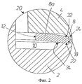
на фиг.2 - увеличенное изображение при виде сбоку вертикального разреза элемента А на фиг. 1, показывающее расположение части листа, находящейся вблизи отверстия в листе, внутри образуемой пресс-формами оформляющей полости перед впрыскиванием термопласта,
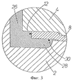
на фиг. 3 - увеличенное изображение элемента, аналогичного элементу на фиг.2, которое показывает расположение листа в оформляющей полости после отливки под давлением термопластового устройства для открывания,
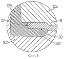
на фиг. 4 - увеличенное изображение элемента, аналогичного элементу на фиг.2, которое показывает пресс-формы согласно другому предпочтительному аспекту изобретения, образующие оформляющую полость, внутри которой расположен лист перед впрыскиванием термопласта,
на фиг. 5 - увеличенное изображение элемента, аналогичного элементу на фиг.4, которое показывает расположение листа в оформляющей полости после отливки под давлением термопластового устройства для открывания, и
на фиг. 6 - увеличенное изображение элемента, аналогичного элементу на фиг.5, которое показывает пресс-формы согласно другому предпочтительному аспекту изобретения, образующие оформляющую полость относительно листа, которая дает возможность впрыскивать термопласт по обеим сторонам листа.in FIG. 1 is a side elevational view of mutually disposed injection molding thermoplastic devices for opening packaging material on a sheet according to one preferred aspect of the invention,
figure 2 is an enlarged image when viewed from the side of a vertical section of the element And in Fig. 1, showing the location of a portion of the sheet adjacent to an opening in the sheet inside formed by molds of the forming cavity before injection of the thermoplastic,
in FIG. 3 is an enlarged image of an element similar to the element in figure 2, which shows the location of the sheet in the forming cavity after injection molding of a thermoplastic opening device,
in FIG. 4 is an enlarged image of an element similar to the element in FIG. 2, which shows molds according to another preferred aspect of the invention forming a forming cavity inside which a sheet is located before injection of the thermoplastic,
in FIG. 5 is an enlarged image of an element similar to the element in figure 4, which shows the location of the sheet in the forming cavity after injection molding of a thermoplastic opening device, and
in FIG. 6 is an enlarged view of an element similar to the element of FIG. 5, which shows molds according to another preferred aspect of the invention, forming a forming cavity relative to the sheet, which makes it possible to inject the thermoplastic on both sides of the sheet.
Как показано на фиг.1, внутренняя пресс-форма 2 и пара наружных пресс-форм 4 и 6 в положении формования взаимно размещены относительно упаковочного листового материала 8 таким образом, что упаковочный листовой материал находится между внутренней пресс-формой 2 и наружными пресс-формами 4 и 6, а пресс-формы образуют оформляющую полость 10, в которой расположен край 12 отверстия, выполненного в листе 8. Кроме того, относительно головки 14 для впрыскивания термопласта пресс-формы расположены с возможностью подачи нагретого термопласта через канал 16 головки 14 в оформляющую полость 10 для того, чтобы после охлаждения нагретого термопласта образовывалось устройство для открывания, соединенное с листом 8 по краю отверстия 12. As shown in FIG. 1, the
Упаковочный листовой материал 8 может быть любого вида и формы. Например, лист 8 может быть в виде непрерывного полотна упаковочного материала, заготовки из упаковочного материала или выступа из упаковочного материала. В другом предпочтительном варианте осуществления изобретения лист 8 представляет собой бумажную основу с пластмассовым покрытием. The
В показанном варианте осуществления изобретения оформляющая полость 10 содержит часть 10а для формования крышки устройства для открывания, часть 10b для формования основания этого устройства, соединяющегося с листом 8, и часть 10с для формования в устройстве для открывания края, имеющего уменьшенную толщину и предназначенного для отрывания крышки от основания этого устройства. Данное описание больше касается, в частности, способа прикрепления устройства для открывания к листу 8 на краю 12 его отверстия, при этом устройство для открывания может быть выполнено в самых разнообразных общих формах. In the shown embodiment, the forming
В показанном варианте осуществления изобретения край 12 отверстия выполнен кольцевым и полностью окружает отверстие в листе 8. Предпочитается, чтобы перед литьем под давлением весь край 12 отверстия находился внутри части 10b оформляющей полости 10, предназначенной для формования основания устройства для открывания. Эта часть 10Ь также выполнена кольцевой и имеет размер, достаточный для помещения всего края 12 отверстия. Край 12 отверстия, часть 10Ь для формования основания устройства для открывания и соединительная часть 10с предпочтительно выполнены в форме овального кольца в продольном поперечном сечении, простирающимся, по существу, параллельно протяженности листа, а часть 10а для формования крышки - в форме овального диска в продольном поперечном сечении, простирающимся также, по существу, параллельно протяженности листа. Кроме того, в положении формования образуется зазор 18 между пресс-формами, который предпочтительно имеет ширину меньше, чем толщина упаковочного листового материала 8, благодаря чему обеспечивается сжатие листа 8 в этом зазоре и образуется уплотнение, достаточное для предотвращения какой-либо значительной утечки нагретого термопласта наружу оформляющей полости 10. In the shown embodiment, the
Положение формования на фиг.1 может быть достигнуто самыми разнообразными способами, очевидными для специалистов в данной области. Например, внутренняя пресс-форма 2 может быть выполнена с возможностью вертикального перемещения вверх и вниз в направлении по стрелке В, а наружные пресс-формы 4 и 6 могут быть выполнены с возможностью вертикального перемещения вверх и вниз и горизонтального перемещения внутрь и наружу в направлениях соответственно С и D, при этом головка для впрыскивания 14 может оставаться, по существу, в неподвижном положении. Когда пресс-формы находятся в полностью раскрытом положении, можно прерывисто подавать упаковочный листовой материал в направлении Е в его правильное положение при должном образом выровненном крае 12 отверстия, после чего можно перемещать пресс-формы в их полностью сомкнутое положение, соответствующее положению формования на фиг.1, и подавать нагретый термопласт по каналу 16 головки для впрыскивания 14 с целью заполнения оформляющей полости 10 и формования на листе устройства для открывания. После раскрытия пресс-форм можно вновь подавать лист 8 в направлении Е так, чтобы располагать край 12 другого отверстия в правильном положении для воспринятия устройства для открывания. После образования на листе устройства для открывания можно формовать упаковочную тару из листа, наполнять ее продуктом и запечатывать. Способы и устройства для подачи листа 8, штамповки отверстий в листе 12, перемещения пресс-форм, впрыскивания нагретых термопластов, формования, наполнения и запечатывания упаковочной тары очевидны для специалистов в данной области. The molding position in FIG. 1 can be achieved in a wide variety of ways, obvious to those skilled in the art. For example, the
На фиг.2 показана оформляющая конфигурация 20 внутренней и наружной пресс-форм в положении, соответствующем положению формования на фиг.1. Внутренняя пресс-форма 2 расположена в соприкосновении с внутренней боковой поверхностью 22 листа 8, а наружная пресс-форма 4 - в соприкосновении с его наружной боковой поверхностью 24. Оформляющая конфигурация 20 наружной и внутренней пресс-форм обеспечивает смещение части упаковочного листового материала 8, расположенной вблизи края 12 отверстия, от внутренней пресс-формы 2. После того, как достигнуто смещение листа 8, можно впрыскивать нагретый термопласт в оформляющую полость 10 для формования устройства для открывания 26, прикрепленного к краю 12 отверстия в листе 8 (фиг.3). Благодаря смещению листа 8 от внутренней пресс-формы обеспечивается формование пластмассовой части 28 на части 30 внутренней боковой поверхности 22 листа 8, расположенной вблизи края 12 отверстия. Figure 2 shows the
Благодаря смещению листа 8 в оформляющей полости 10 и точному формованию пластмассовой части 28 достигаются единообразие и надежность в отношении правильного размещения листа относительно устройства для открывания 26, так как во время стадии литья под давлением лист удерживается в правильном и смещенном положении. Кроме того, формование пластмассовой части 28 на части 30 внутренней боковой поверхности вблизи края 12 отверстия обеспечивает эффективное образование отличного уплотнения по краю отверстия и на внутренней боковой поверхности листа, которое с пользой способствует обеспечению того, что продукты не будут входить в соприкосновение с внутренними слоями листа, когда в готовой упаковочной таре внутренняя боковая поверхность упаковочного листового материала предназначена быть поверхностью, соприкасающейся с пищевым продуктом. Due to the displacement of the
Оформляющая конфигурация 20 внутренней пресс-формы 2 и наружной пресс-формы 4 содержит край наружной пресс-формы 4, который соприкасается с наружной боковой поверхностью 24 упаковочного листового материала 8 по первой линии соприкосновения 32, и край внутренней пресс-формы 2, который соприкасается с внутренней боковой поверхностью 22 упаковочного листового материала 8 по второй линии соприкосновения 34, при этом первая линия соприкосновения 32 расположена от края 12 отверстия дальше, чем вторая линия соприкосновения 34. Сжатие листа 8 внутри более узкого зазора 18, образованного между наружной и внутренней пресс-формами, и пространственное расположение первой и второй линий соприкосновения 32 и 34 обуславливают то, что часть 8а листа 8, расположенная вблизи края 12 отверстия, изгибается под углом к плоскости протяженности листа, расположенной непосредственно снаружи оформляющей полости 10, благодаря чему достигается смещение такой части 8а листа от внутренней пресс-формы 2. The
Как показано на фиг.2, в положении формования оформляющая конфигурация 20 внутренней и наружной пресс-форм представлена таким образом, что край 12 отверстия в листе 8, по существу, соприкасается с наружной пресс-формой 4. Таким образом, во время стадии впрыскивания термопласта не происходит формование пластмассы на наружной боковой поверхности 24 листа, как это видно на фиг. 3. Однако можно так профилировать наружную пресс-форму 4, чтобы край 12 отверстия не соприкасался с наружной пресс-формой 4 даже после смещения части 8а листа от нижней пресс-формы 2. Таким образом, устройство для открывания, формованное на стадии впрыскивания термопласта, будет содержать пластмассовые части, покрывающие как внутреннюю, так и наружную поверхности листа вблизи края отверстия. Кроме того, на фиг.3, показаны небольшие пластмассовые части устройства для открывания 26, расположенные в зазоре 18 между внутренней пресс-формой 2 и внутренней боковой поверхностью 22 листа 8 и формованные во время стадии литья под обычно высоким давлением. Однако сжатие листа 8 в зазоре 18 достаточно для образования уплотнения, которое в достаточной степени предотвращает какую-либо значительную утечку нагретого термопласта наружу оформляющей полости 10 через зазор 18. As shown in FIG. 2, in the molding position, the forming
Хотя в описанном варианте осуществления изобретения, показанном на фиг. 1-3, часть 8а листа смещена от внутренней пресс-формы 2, предполагается также, что, изменяя относительные положения линий соприкосновения 32 и 34 таким образом, чтобы первая линия соприкосновения 32 находилась ближе к краю 12 отверстия, чем вторая линия соприкосновения 34, можно при желании смещать часть 8а листа от наружной пресс-формы 4. Таким образом, конкретное взаимное относительное расстояние между линиями соприкосновения, определяющее степень и направление изгиба части 8а листа, и конкретная конфигурация образуемой пресс-формами оформляющей полости по отношению к краю отверстия в листе, определяющая место формования пластмассовых частей, будут диктовать конкретное расположение части 8а листа в этой полости в положении формования для обеспечения того, что будут эффективно и действенно достигаться желаемые окончательное соединение устройства для открывания с листом и его точное расположение на листе. Although in the described embodiment of the invention shown in FIG. 1-3, part 8a of the sheet is offset from the
На фиг. 4 показан другой вариант осуществления изобретения, в котором оформляющая конфигурация 120 внутренней и наружной пресс-форм 102 и 104, взаимно установленных в положении формования, представлена таким образом, что внутренняя пресс-форма 102 расположена в соприкосновении с внутренней боковой поверхностью 22 листа 8 и наружная пресс-форма 104 - в соприкосновении с наружной боковой поверхностью 24 листа 8 для сжатия листа 8 в более узком зазоре 118 между пресс-формами и что край 12 отверстия находится в оформляющей полости 110, образованной внутренней и наружной пресс-формами. Кроме того, оформляющая конфигурация 120 наружной и внутренней пресс-форм 102 и 104 обеспечивает смещение части 8а упаковочного листового материала 8, расположенной вблизи края 12 отверстия, от внутренней пресс-формы 102. После того, как достигнуто смещение листа 8, впрыскивают нагретый термопласт в оформляющую полость 110 для формования устройства для открывания 126, прикрепленного к краю 12 отверстия в листе 8 (фиг.5). Смещение части 8а листа от внутренней пресс-формы обеспечивает формование пластмассовой части 128 на части 30 внутренней боковой поверхности 22 части 8а листа, расположенной вблизи края 12 отверстия. Благодаря смещению части 8а листа в оформляющей полости 110 и точному формованию пластмассовой части 128 достигаются единообразие и надежность в отношении правильного размещения листа 8 относительно устройства для открывания 126, так как во время стадии литья под давлением лист удерживается в правильном и смещенном положении. Формование пластмассовой части 128 на части 30 внутренней боковой поверхности листа вблизи края 12 отверстия обеспечивает отличное уплотнение по краю отверстия и на внутренней боковой поверхности листа, которое способствует обеспечению того, что продукты не будут входить в соприкосновение с внутренними слоями листа, когда в готовой упаковочной таре внутренняя боковая поверхность упаковочного листового материала предназначена быть поверхностью, соприкасающейся с пищевым продуктом. In FIG. 4 shows another embodiment of the invention in which the forming
В оформляющей конфигурации 120 зазор 118, образованный между внутренней и наружной пресс-формами 102 и 104, имеет протяженность в плоскости, простирающейся в оформляющей полости под углом в направлении от внутренней пресс-формы 102 так, чтобы происходило смещение части 8а листа от внутренней пресс-формы 102, достаточное для надежного формования пластмассовой части на части 30 внутренней боковой поверхности листа. В варианте на фиг.4 и 5 линии соприкосновения, по которым края внутренней и наружной пресс-форм соприкасаются с внутренней и наружной поверхностями листа 8, расположены, по существу, напротив друг друга, и, следовательно, не происходит изгибание части 8а листа относительно протяженности зазора 118. Желаемое соединение устройства для открывания 126 с листом 8 и размещение на нем эффективно достигаются скорее благодаря протяженности самого зазора 118, который обеспечивает достаточное смещение части 8а от внутренней пресс-формы 102. Кроме того, как считают, сочетание изгибания части 8а листа способом, описанным со ссылкой на вариант на фиг. 1-3 и осуществляемым разделением друг от друга линий соприкосновения между краями внутренней и наружной пресс-формами и внутренней и наружной поверхностями листа, с расположением части 8а под углом в оформляющей полости 110, обуславливаемым зазором 118, может обеспечить смещение части 8а в оформляющей полости, подходящее для достижения желаемого точного размещения устройства для открывания на листе. In the forming
Как показано на фиг.4, край 12 отверстия в листе 8 находится с небольшим промежутком от верхней пресс-формы 104 в положении формования. Однако этот небольшой промежуток все же обеспечивает то, что нагретый термопласт, входящий в оформляющую полость 110 во время стадии впрыскивания, будет отжимать часть 8а листа в соприкосновение с наружной пресс-формой так, чтобы при желании не происходило формование пластмассовой части на верхней боковой поверхности листа 8. As shown in figure 4, the
На фиг. 6 показана разновидность варианта осуществления изобретения на фиг.4-5, в которой оформляющая конфигурация 220, образуемая внутренней пресс-формой 202 и наружной пресс-формой 204, содержит простирающийся под углом зазор 218 для смещения части 8а листа в оформляющей полости 210 от внутренней пресс-формы 202, при этом имеется интервал между частью 8а листа и наружной пресс-формой 204, который является достаточно большим, чтобы после стадии впрыскивания термопласта образовывалось бы устройство для формования 226, которое содержит как пластмассовую часть 236, расположенную на наружной боковой поверхности 238 части 8а листа, так и пластмассовую часть 228, расположенную на внутренней боковой поверхности 230 части 8а листа. In FIG. 6 shows a variation of the embodiment of FIGS. 4-5, in which the forming
Хотя в описанных вариантах осуществления изобретения, показанных на фиг. 4-6, часть 8а листа смещена от внутренней пресс-формы, предполагается также, что при желании можно, изменив направление протяженности зазора в оформляющей конфигурации, смещать часть 8а листа от наружной пресс-формы. Таким образом, конкретная протяженность зазора в оформляющей конфигурации, определяющая направление протяженности части листа, и конкретная конфигурация образованной пресс-формами оформляющей полости по отношению к краю отверстия в листе, определяющая место формования пластмассовых частей, будут диктовать конкретное расположение части листа в этой полости в положении формования для обеспечения того, что будут эффективно и действенно достигаться желаемые окончательное соединение устройства для открывания с листом и его точное расположение на листе. Although in the described embodiments of the invention shown in FIG. 4-6, the sheet portion 8a is offset from the inner mold, it is also contemplated that, if desired, it is possible to shift the sheet portion 8a from the outer mold by changing the length of the gap in the design configuration. Thus, the specific length of the gap in the forming configuration, which determines the direction of the length of the sheet part, and the specific configuration of the forming cavity formed by the molds with respect to the edge of the hole in the sheet, determining the place where the plastic parts are formed, will dictate the specific location of the sheet part in this cavity in position molding to ensure that the desired final connection of the opening device with the sheet and its precise distribution are achieved efficiently and effectively Proposition on the sheet.
Claims (5)
Applications Claiming Priority (3)
| Application Number | Priority Date | Filing Date | Title |
|---|---|---|---|
| IT96MI002271A IT1287126B1 (en) | 1996-10-31 | 1996-10-31 | PROCEDURE AND MOLD TOOLS FOR INJECTION MOLDING OF A PART OF PLASTIC MATERIAL IN A PACKAGING SHEET MATERIAL |
| ITM196A002271 | 1996-10-31 | ||
| ITMI96A002271 | 1996-10-31 |
Publications (2)
| Publication Number | Publication Date |
|---|---|
| RU99111779A RU99111779A (en) | 2001-02-27 |
| RU2199439C2 true RU2199439C2 (en) | 2003-02-27 |
Family
ID=11375134
Family Applications (1)
| Application Number | Title | Priority Date | Filing Date |
|---|---|---|---|
| RU99111779/12A RU2199439C2 (en) | 1996-10-31 | 1997-09-23 | Method and mould for injection molding of plastic part in packing plate material |
Country Status (23)
| Country | Link |
|---|---|
| US (1) | US6251325B1 (en) |
| EP (1) | EP0935522B1 (en) |
| JP (1) | JP3989024B2 (en) |
| KR (1) | KR100364376B1 (en) |
| CN (1) | CN1101306C (en) |
| AR (1) | AR008518A1 (en) |
| AT (1) | ATE218424T1 (en) |
| AU (1) | AU718228B2 (en) |
| BR (1) | BR9712615A (en) |
| CA (1) | CA2270467C (en) |
| DE (1) | DE69713127T2 (en) |
| DK (1) | DK0935522T3 (en) |
| ES (1) | ES2178005T3 (en) |
| FI (1) | FI114300B (en) |
| HK (1) | HK1024664A1 (en) |
| HU (1) | HU222203B1 (en) |
| IT (1) | IT1287126B1 (en) |
| NO (1) | NO314171B1 (en) |
| PL (1) | PL184640B1 (en) |
| RU (1) | RU2199439C2 (en) |
| TR (1) | TR199900931T2 (en) |
| UA (1) | UA66348C2 (en) |
| WO (1) | WO1998018609A1 (en) |
Cited By (1)
| Publication number | Priority date | Publication date | Assignee | Title |
|---|---|---|---|---|
| RU2550183C2 (en) * | 2010-01-25 | 2015-05-10 | Конинклейке Филипс Электроникс Н.В. | Method to manufacture device comprising at least one moved working element and also such device |
Families Citing this family (16)
| Publication number | Priority date | Publication date | Assignee | Title |
|---|---|---|---|---|
| GB2330791B (en) | 1997-10-30 | 2002-05-08 | Boucherie Nv G B | Method of molding toothbrushes and apparatus for performing the method |
| SE521876C2 (en) | 1999-12-22 | 2003-12-16 | Tetra Laval Holdings & Finance | Multi-stage unit for processing a web-shaped packaging material in a food packaging machine |
| US6467238B1 (en) | 2000-06-15 | 2002-10-22 | Tetra Laval Holdings & Finance, Sa | Direct injection molded closure and method therefor |
| DK1170217T3 (en) | 2000-07-07 | 2003-09-15 | Tetra Laval Holdings & Finance | Unit for processing a web of packaging material for the production of sealed packages of liquid foods |
| SE523936C2 (en) | 2001-12-19 | 2004-06-01 | Tetra Laval Holdings & Finance | Injection molding tools and methods of injection molding |
| US7059466B2 (en) | 2004-01-23 | 2006-06-13 | Tetra Laval Holdings & Finance, Sa | Carton transfer unit |
| US7313895B2 (en) | 2004-07-20 | 2008-01-01 | Tetra Laval Holdings & Finance, Sa | Molding unit for forming direct injection molded closures |
| ATE466714T1 (en) * | 2006-01-27 | 2010-05-15 | Tetra Laval Holdings & Finance | METHOD AND DEVICE FOR ATTACHING OPENING DEVICES TO PACKAGING FOR FLOWABLE FOODS |
| SE0702568L (en) | 2007-11-21 | 2008-09-16 | Tetra Laval Holdings & Finance | Device for reshaping material web |
| US8591792B2 (en) * | 2010-12-28 | 2013-11-26 | Kojima Press Industry Co., Ltd. | Method of molding a first resin member on a second resin member |
| DE102011108156A1 (en) * | 2011-07-20 | 2013-01-24 | Daimler Ag | Connection structure for a motor vehicle and method for its production |
| IL238861A (en) * | 2015-05-17 | 2017-10-31 | Katzin Asaf | Apparatus and method of forming connector brackets for irrigation laterals along an already made lay-flat pipe |
| NL2019232B1 (en) * | 2017-07-11 | 2019-01-28 | Pixsweet B V | Confection package |
| JP7353045B2 (en) * | 2019-03-11 | 2023-09-29 | 藤森工業株式会社 | Container and its manufacturing method |
| EP4200112A2 (en) * | 2020-08-21 | 2023-06-28 | Plastipak Packaging, Inc. | Multi-layer nozzle, method, and articles made therefrom |
| EP4289588A1 (en) * | 2022-06-06 | 2023-12-13 | Tetra Laval Holdings & Finance S.A. | Molding tool, molding apparatus having a molding tool and packaging machine having a molding apparatus |
Family Cites Families (8)
| Publication number | Priority date | Publication date | Assignee | Title |
|---|---|---|---|---|
| US2821764A (en) * | 1954-03-11 | 1958-02-04 | United Shoe Machinery Corp | Plastic grommets and a method for forming them |
| GB1023886A (en) * | 1963-09-25 | 1966-03-30 | Metal Containers Ltd | Method of and mould for forming a bushing in an opening in a sheet material wall,and sheet material wall produced by said method |
| SE370203B (en) * | 1972-12-18 | 1974-10-07 | Cerbo Ab | |
| US4244491A (en) * | 1977-12-15 | 1981-01-13 | Tokan Kogyo Co., Ltd. | Container cover member having synthetic resin openable portion |
| GB8523263D0 (en) * | 1985-09-20 | 1985-10-23 | Metal Box Plc | Making metal can ends |
| US4956139A (en) * | 1987-10-06 | 1990-09-11 | Canon Denshi Kabushiki Kaisha | Method of producing an exposure blade |
| SE462743B (en) | 1988-12-16 | 1990-08-27 | Profor Ab | SETTING TO JOIN A GRIP ORGAN WITH A SHEET OR TRAFFIC PACKAGING LAMINATE |
| CN1066037A (en) * | 1991-04-22 | 1992-11-11 | 天龙化学工业株式会社 | The lid arrangement of large container |
-
1996
- 1996-10-31 IT IT96MI002271A patent/IT1287126B1/en active IP Right Grant
-
1997
- 1997-09-23 CA CA002270467A patent/CA2270467C/en not_active Expired - Fee Related
- 1997-09-23 CN CN97199296A patent/CN1101306C/en not_active Expired - Lifetime
- 1997-09-23 JP JP52034698A patent/JP3989024B2/en not_active Expired - Lifetime
- 1997-09-23 DK DK97943263T patent/DK0935522T3/en active
- 1997-09-23 DE DE69713127T patent/DE69713127T2/en not_active Expired - Lifetime
- 1997-09-23 EP EP97943263A patent/EP0935522B1/en not_active Expired - Lifetime
- 1997-09-23 BR BR9712615-2A patent/BR9712615A/en not_active IP Right Cessation
- 1997-09-23 HU HU9903853A patent/HU222203B1/en not_active IP Right Cessation
- 1997-09-23 WO PCT/SE1997/001596 patent/WO1998018609A1/en active IP Right Grant
- 1997-09-23 AU AU44777/97A patent/AU718228B2/en not_active Ceased
- 1997-09-23 KR KR1019997003861A patent/KR100364376B1/en not_active IP Right Cessation
- 1997-09-23 RU RU99111779/12A patent/RU2199439C2/en not_active IP Right Cessation
- 1997-09-23 ES ES97943263T patent/ES2178005T3/en not_active Expired - Lifetime
- 1997-09-23 AT AT97943263T patent/ATE218424T1/en active
- 1997-09-23 UA UA99042441A patent/UA66348C2/en unknown
- 1997-09-23 US US09/269,505 patent/US6251325B1/en not_active Expired - Lifetime
- 1997-09-23 TR TR1999/00931T patent/TR199900931T2/en unknown
- 1997-09-23 PL PL97333142A patent/PL184640B1/en unknown
- 1997-10-31 AR ARP970105092A patent/AR008518A1/en active IP Right Grant
-
1999
- 1999-04-29 FI FI990979A patent/FI114300B/en not_active IP Right Cessation
- 1999-04-30 NO NO19992115A patent/NO314171B1/en not_active IP Right Cessation
-
2000
- 2000-07-03 HK HK00104022A patent/HK1024664A1/en not_active IP Right Cessation
Cited By (1)
| Publication number | Priority date | Publication date | Assignee | Title |
|---|---|---|---|---|
| RU2550183C2 (en) * | 2010-01-25 | 2015-05-10 | Конинклейке Филипс Электроникс Н.В. | Method to manufacture device comprising at least one moved working element and also such device |
Also Published As
Similar Documents
| Publication | Publication Date | Title |
|---|---|---|
| RU2199439C2 (en) | Method and mould for injection molding of plastic part in packing plate material | |
| EP0949992B1 (en) | Apparatus and method for moulding an opening device on a packaging sheet | |
| CA2204590C (en) | Plastic container component and method of forming the same | |
| JP4634653B2 (en) | Direct injection molded closure and method therefor | |
| US20110024439A1 (en) | Packaging with a subsequently molded form-fit connection | |
| CN111746930B (en) | Opening device for packages of pourable products and package comprising opening device | |
| US20010035424A1 (en) | Hinged container lid assembly | |
| HU213058B (en) | Closable discharging hole on fluid-storing bottles and/or boxlike packages and method for producing same | |
| CN1235580A (en) | Opening device on packaging sheet material | |
| US7571846B2 (en) | Carton blank for direct injection molded closures | |
| US4887765A (en) | Fluid pack and process for the production thereof | |
| MXPA05003794A (en) | An opening arrangement, a package, as well as a method of providing a package with an opening arrangement. | |
| JPH0375018B2 (en) | ||
| CA2429617C (en) | Method for applying an opening device to a packaging material and package obtained thereby | |
| MXPA99003905A (en) | Method and mould tools for injection moulding a plastics material part in a packaging sheet material | |
| JP3388360B2 (en) | Mold for molding of cylindrical molded products |
Legal Events
| Date | Code | Title | Description |
|---|---|---|---|
| MM4A | The patent is invalid due to non-payment of fees |
Effective date: 20160924 |