EP0935313A1 - Vorrichtung zur Ver- und Entriegelung eines an einem Mehrleiterkabel angeschlossenen Verbinders mit einer Buchse - Google Patents
Vorrichtung zur Ver- und Entriegelung eines an einem Mehrleiterkabel angeschlossenen Verbinders mit einer Buchse Download PDFInfo
- Publication number
- EP0935313A1 EP0935313A1 EP99101543A EP99101543A EP0935313A1 EP 0935313 A1 EP0935313 A1 EP 0935313A1 EP 99101543 A EP99101543 A EP 99101543A EP 99101543 A EP99101543 A EP 99101543A EP 0935313 A1 EP0935313 A1 EP 0935313A1
- Authority
- EP
- European Patent Office
- Prior art keywords
- connector
- socket
- shaped spring
- base
- spring
- Prior art date
- Legal status (The legal status is an assumption and is not a legal conclusion. Google has not performed a legal analysis and makes no representation as to the accuracy of the status listed.)
- Granted
Links
- 239000004020 conductor Substances 0.000 claims abstract description 10
- 230000000295 complement effect Effects 0.000 claims abstract description 9
- 239000011810 insulating material Substances 0.000 claims description 3
- 230000001771 impaired effect Effects 0.000 description 1
- 238000000034 method Methods 0.000 description 1
- 238000012986 modification Methods 0.000 description 1
- 230000004048 modification Effects 0.000 description 1
Images

Classifications
-
- H—ELECTRICITY
- H01—ELECTRIC ELEMENTS
- H01R—ELECTRICALLY-CONDUCTIVE CONNECTIONS; STRUCTURAL ASSOCIATIONS OF A PLURALITY OF MUTUALLY-INSULATED ELECTRICAL CONNECTING ELEMENTS; COUPLING DEVICES; CURRENT COLLECTORS
- H01R13/00—Details of coupling devices of the kinds covered by groups H01R12/70 or H01R24/00 - H01R33/00
- H01R13/62—Means for facilitating engagement or disengagement of coupling parts or for holding them in engagement
- H01R13/627—Snap or like fastening
- H01R13/6275—Latching arms not integral with the housing
-
- H—ELECTRICITY
- H01—ELECTRIC ELEMENTS
- H01R—ELECTRICALLY-CONDUCTIVE CONNECTIONS; STRUCTURAL ASSOCIATIONS OF A PLURALITY OF MUTUALLY-INSULATED ELECTRICAL CONNECTING ELEMENTS; COUPLING DEVICES; CURRENT COLLECTORS
- H01R13/00—Details of coupling devices of the kinds covered by groups H01R12/70 or H01R24/00 - H01R33/00
- H01R13/62—Means for facilitating engagement or disengagement of coupling parts or for holding them in engagement
- H01R13/629—Additional means for facilitating engagement or disengagement of coupling parts, e.g. aligning or guiding means, levers, gas pressure electrical locking indicators, manufacturing tolerances
- H01R13/62933—Comprising exclusively pivoting lever
-
- H—ELECTRICITY
- H01—ELECTRIC ELEMENTS
- H01R—ELECTRICALLY-CONDUCTIVE CONNECTIONS; STRUCTURAL ASSOCIATIONS OF A PLURALITY OF MUTUALLY-INSULATED ELECTRICAL CONNECTING ELEMENTS; COUPLING DEVICES; CURRENT COLLECTORS
- H01R13/00—Details of coupling devices of the kinds covered by groups H01R12/70 or H01R24/00 - H01R33/00
- H01R13/66—Structural association with built-in electrical component
- H01R13/665—Structural association with built-in electrical component with built-in electronic circuit
- H01R13/6658—Structural association with built-in electrical component with built-in electronic circuit on printed circuit board
Definitions
- the present invention relates to a device for locking and unlocking a connector, connected to a cable having several conductors, with respect to a socket, the said connector consisting mainly of a printed-circuit board connected to the said conductors.
- the socket may, for example, be fixed to an apparatus such as a mobile telephone intended to be connected, by means of the cable, to a power supply provided inside a motor vehicle.
- the connector is connected to the socket by means of a plug carrying several connection pins which can be plugged into female contacts fastened to the socket.
- this device is characterized in that the connector carries a generally U-shaped spring, the arms of which have, at their ends, means which engage with complementary means in order to lock the connector to the socket, and in that the connector has a pivoting lever carrying a member which engages with the base of the generally U-shaped spring, this member being able to move, when the lever pivots, between a position in which the said member is inactive with respect to the base of the said spring and the arms of the spring are locked to the socket and a position in which the said member exerts a force on the base of the said spring in order to unlock the arms of the latter from the socket.
- the generally U-shaped spring constitutes a simple and reliable means for locking the connector to the socket.
- the printedcircuit board connected to the cable is pressed against a plug made of insulating material containing several contact pins that are connected to the conductors of the cable via the printed circuit of the said board, these contact pins projecting from the said plug and making electrical connections with female contacts of the said socket when the latter is locked to the connector, the said generally U-shaped spring going around the board and the plug.
- the plug is thus confined inside the U of the spring and this makes it possible to obtain a structure which is compact and simple to produce.
- a support is placed between the printed-circuit board and the base of the said U-shaped spring.
- the plug, the printed-circuit board and the U-shaped spring are housed in a casing, the end of the cable having an end-piece which has a projecting part held in place in a cavity in the casing, and the casing is closed by a cover which covers the base of the U-shaped spring and the said support, this cover having a cavity complementary to that provided in the casing in order to hold the projecting part of the end-piece of the cable in place.
- the connector fitted with the locking and unlocking device according to the invention is thus composed of a small number of pieces and has a very compact structure.
- the locking and unlocking device composed of a lever and of a U-shaped spring does not complicate the production of the connector and has no appreciable impact on its size.
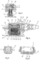
- Figures 1 and 2 show a connector 1 connected to a cable 2 having several conductors 3.
- This connector consists of a printed-circuit board 4 connected to the conductors 3.
- the connector 1 carries a generally U-shaped spring 5 (see Figures 2 and 4), the side arms 5a of which have, at their ends, means 6 which engage with complementary means 7 in order to lock the connector to a socket 8.
- the connector 1 has, on the other hand, (see Figures 2 and 3) a pivoting lever 9 carrying a member 10 (see Figures 2 and 4) which engages with the base 5b of the generally U-shaped spring 5.
- This member 10 can move, when the lever 9 pivots, between a position (that shown in Figure 4) in which this member 10 is inactive with respect to the base 5b of the spring 5 and the arms 5a of the spring are locked to the socket 8 and a position (not shown) in which this member 10 exerts a force on the base 5b of the spring in order to unlock the arms 5a of the latter from the socket 8.
- the printed-circuit board 4 connected to the cable is pressed against a plug 11 made of insulating material containing several contact pins 12 that are connected to the conductors 3 of the cable 2 via the printed circuit of the board 4. These contact pins 12 project from the plug 11 and make electrical connections with female contacts 13 carried by the socket 8 (see also Figure 6) when the latter is locked to the connector 1.
- Figure 4 also shows that the generally U-shaped spring 5 goes around the board 4 and a plug 11.
- a support 14 is placed between the printed-circuit board 4 and the base 5b of the U-shaped spring.
- the plug 11, the printed-circuit board 4 and the U-shaped spring are housed in a casing 15.
- the end of the cable 2 has an end-piece 16 which has a projecting part 17 held in place in a cavity 18 in the casing 15 (see Figures 2 and 4).
- the casing 15 is closed by a cover 19 which covers the base 5b of the U-shaped spring 5 and the support 14.
- This cover 19 has a cavity 20 complementary to that provided in the casing 15 in order to hold the projecting part 17 of the end-piece 16 of the cable 2 in place.
- the lever 9 has, at one of its ends, a pivot 21 mounted in complementary recesses 22, 23 made in the cover 19 and in the casing 15, the axis of the pivot being approximately parallel to the contact pins 12 of the plug 11 and perpendicular to the printed-circuit board 4.
- the member 10 which engages with the base 5b of the U-shaped spring 5 lies between the pivot 21 of the lever 9 and its end opposite this pivot.
- the member 10 has a cam 24 engaged between the base 5b of the approximately U-shaped spring 5 and the support 14.
- the base 5b of the U-shaped spring 5 is shaped in the form of a dihedron (see Figures 2 and 4), the apex of which faces the support 14.
- the cam 24 of the member 10 carried by the lever 9 is inserted between an inclined part of the dihedron and a rectilinear face of the support 14.
- a return spring 25 (see Figures 2 and 3) is placed between the support 14 and a part of the lever 9 which lies between the pivot 21 and the member 10 having the cam 24.
- the support 14 (see Figures 2 and 4) has, at its two opposite ends, a rounded surface 26 for supporting and for guiding the opposite ends of the base 5b of the U-shaped spring 5.
- the ends of the arms 5a of the U-shaped spring 5 have catches 6 which face the outside and are engaged in openings 7 made in tabs 27 (see Figures 5 and 6) fastened to the socket 8.
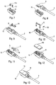
- lever 9 is pushed back sideways, towards the outside of the connector, by the return spring 25.
- the contact pins 12 and the springs 12a are put into place (see Figure 7) in the plug 11.
- the support 14 is placed (see Figure 9) on the board 4 lying in the casing 15.
- the U-shaped spring 5 is engaged (see Figure 10) on the support 14 and the return spring 25 is put into place.
- the lever 9 is put into position (see Figure 11) by engaging the member 10 of the latter between the base of the spring 5 and the support 14.
- the cover 19 is placed (see Figure 12) on the casing 15.
Landscapes
- Details Of Connecting Devices For Male And Female Coupling (AREA)
- Coupling Device And Connection With Printed Circuit (AREA)
Applications Claiming Priority (2)
| Application Number | Priority Date | Filing Date | Title |
|---|---|---|---|
| FR9801366 | 1998-02-05 | ||
| FR9801366A FR2774516B1 (fr) | 1998-02-05 | 1998-02-05 | Dispositif de verrouillage et de deverrouillage d'un connecteur raccorde a un cable a plusieurs conducteurs, par rapport a une embase |
Publications (2)
| Publication Number | Publication Date |
|---|---|
| EP0935313A1 true EP0935313A1 (de) | 1999-08-11 |
| EP0935313B1 EP0935313B1 (de) | 2006-05-10 |
Family
ID=9522642
Family Applications (1)
| Application Number | Title | Priority Date | Filing Date |
|---|---|---|---|
| EP19990101543 Expired - Lifetime EP0935313B1 (de) | 1998-02-05 | 1999-01-29 | Vorrichtung zur Ver- und Entriegelung eines an einem Mehrleiterkabel angeschlossenen Verbinders mit einer Buchse |
Country Status (3)
| Country | Link |
|---|---|
| EP (1) | EP0935313B1 (de) |
| DE (1) | DE69931202T2 (de) |
| FR (1) | FR2774516B1 (de) |
Cited By (2)
| Publication number | Priority date | Publication date | Assignee | Title |
|---|---|---|---|---|
| US6692312B1 (en) | 1999-11-10 | 2004-02-17 | Ralph Semmeling | Receptacle and plug connectors |
| CN113131273A (zh) * | 2021-04-16 | 2021-07-16 | 广州飞傲电子科技有限公司 | 一种可换接口电连接装置 |
Families Citing this family (1)
| Publication number | Priority date | Publication date | Assignee | Title |
|---|---|---|---|---|
| FR2806218B1 (fr) | 2000-03-10 | 2004-09-10 | Framatome Connectors Int | Connecteur d'entree/sortie du type fiche |
Citations (2)
| Publication number | Priority date | Publication date | Assignee | Title |
|---|---|---|---|---|
| EP0318719A2 (de) * | 1987-11-30 | 1989-06-07 | Grote & Hartmann GmbH & Co. KG | Elektrischer Steckverbinder |
| EP0547252A1 (de) * | 1991-12-14 | 1993-06-23 | Molex Incorporated | Verriegelungsvorrichtung, insbesondere für Einspritz-Stecker |
-
1998
- 1998-02-05 FR FR9801366A patent/FR2774516B1/fr not_active Expired - Fee Related
-
1999
- 1999-01-29 EP EP19990101543 patent/EP0935313B1/de not_active Expired - Lifetime
- 1999-01-29 DE DE69931202T patent/DE69931202T2/de not_active Expired - Fee Related
Patent Citations (2)
| Publication number | Priority date | Publication date | Assignee | Title |
|---|---|---|---|---|
| EP0318719A2 (de) * | 1987-11-30 | 1989-06-07 | Grote & Hartmann GmbH & Co. KG | Elektrischer Steckverbinder |
| EP0547252A1 (de) * | 1991-12-14 | 1993-06-23 | Molex Incorporated | Verriegelungsvorrichtung, insbesondere für Einspritz-Stecker |
Cited By (2)
| Publication number | Priority date | Publication date | Assignee | Title |
|---|---|---|---|---|
| US6692312B1 (en) | 1999-11-10 | 2004-02-17 | Ralph Semmeling | Receptacle and plug connectors |
| CN113131273A (zh) * | 2021-04-16 | 2021-07-16 | 广州飞傲电子科技有限公司 | 一种可换接口电连接装置 |
Also Published As
| Publication number | Publication date |
|---|---|
| FR2774516A1 (fr) | 1999-08-06 |
| EP0935313B1 (de) | 2006-05-10 |
| DE69931202T2 (de) | 2007-02-15 |
| DE69931202D1 (de) | 2006-06-14 |
| FR2774516B1 (fr) | 2000-04-07 |
Similar Documents
| Publication | Publication Date | Title |
|---|---|---|
| JP3451393B2 (ja) | プラグコネクタ及びソケットコネクタ | |
| EP0947944B1 (de) | Verbinder für Kartenleser | |
| JP4522144B2 (ja) | 電気コネクタ | |
| EP1111728B1 (de) | Steckverbinder mit verbessertem Führungsteil zum Führen der Verbindung des Steckverbinders und des Gegensteckers | |
| FI118935B (fi) | Sähköliitin | |
| US20050020125A1 (en) | Electrical connector for flexible printed circuit board | |
| KR100211095B1 (ko) | 납작 케이블용 무삽발력 전기 커넥터 | |
| CN102210067B (zh) | 连接器装置 | |
| US5951317A (en) | Accessory connector assembly | |
| US7063559B2 (en) | Flexible printed circuit electrical connector | |
| EP2850698B1 (de) | Verbinder für leiterplatten | |
| HK1042990B (en) | Connector excellent in reliability of contact | |
| JPH06333632A (ja) | 電気コネクタ組立体 | |
| KR100344048B1 (ko) | Pga 패키지용의 점검 가능한 전기 커넥터 | |
| CN100477398C (zh) | 易于增加用来保持连接对象的保持力的连接器 | |
| CN101283485B (zh) | 连接器 | |
| JP2683709B2 (ja) | 無挿入力電気コネクタ | |
| US5984704A (en) | Zif connector having means for keeping flexible contact sheet in tensile condition | |
| EP0810689B1 (de) | Batterieverbinder | |
| EP0935313B1 (de) | Vorrichtung zur Ver- und Entriegelung eines an einem Mehrleiterkabel angeschlossenen Verbinders mit einer Buchse | |
| CN100539309C (zh) | 连接器 | |
| JP3000197B2 (ja) | Fpc多列zifコネクタ | |
| JP3377060B2 (ja) | 遊動型電気コネクタ及びそれを有する電気コネクタ組立体 | |
| WO2001049718A3 (en) | Electrical connector with lock | |
| EP0776067A2 (de) | Elektrischer Verbinder für Flachkabel |
Legal Events
| Date | Code | Title | Description |
|---|---|---|---|
| PUAI | Public reference made under article 153(3) epc to a published international application that has entered the european phase |
Free format text: ORIGINAL CODE: 0009012 |
|
| AK | Designated contracting states |
Kind code of ref document: A1 Designated state(s): BE CH DE DK ES FI FR GB IE IT LI NL SE |
|
| AX | Request for extension of the european patent |
Free format text: AL;LT;LV;MK;RO;SI |
|
| 17P | Request for examination filed |
Effective date: 20000113 |
|
| AKX | Designation fees paid |
Free format text: BE CH DE DK ES FI FR GB IE IT LI NL SE |
|
| GRAP | Despatch of communication of intention to grant a patent |
Free format text: ORIGINAL CODE: EPIDOSNIGR1 |
|
| GRAS | Grant fee paid |
Free format text: ORIGINAL CODE: EPIDOSNIGR3 |
|
| GRAA | (expected) grant |
Free format text: ORIGINAL CODE: 0009210 |
|
| RIN1 | Information on inventor provided before grant (corrected) |
Inventor name: RIBEAU, PASCAL Inventor name: DEHAN, CHRISTOPHEFRAMATOME CONNECTORS INTERN. |
|
| RAP1 | Party data changed (applicant data changed or rights of an application transferred) |
Owner name: FCI |
|
| AK | Designated contracting states |
Kind code of ref document: B1 Designated state(s): BE CH DE DK ES FI FR GB IE IT LI NL SE |
|
| PG25 | Lapsed in a contracting state [announced via postgrant information from national office to epo] |
Ref country code: NL Free format text: LAPSE BECAUSE OF FAILURE TO SUBMIT A TRANSLATION OF THE DESCRIPTION OR TO PAY THE FEE WITHIN THE PRESCRIBED TIME-LIMIT Effective date: 20060510 Ref country code: LI Free format text: LAPSE BECAUSE OF FAILURE TO SUBMIT A TRANSLATION OF THE DESCRIPTION OR TO PAY THE FEE WITHIN THE PRESCRIBED TIME-LIMIT Effective date: 20060510 Ref country code: IT Free format text: LAPSE BECAUSE OF FAILURE TO SUBMIT A TRANSLATION OF THE DESCRIPTION OR TO PAY THE FEE WITHIN THE PRE;WARNING: LAPSES OF ITALIAN PATENTS WITH EFFECTIVE DATE BEFORE 2007 MAY HAVE OCCURRED AT ANY TIME BEFORE 2007. THE CORRECT EFFECTIVE DATE MAY BE DIFFERENT FROM THE ONE RECORDED.SCRIBED TIME-LIMIT Effective date: 20060510 Ref country code: CH Free format text: LAPSE BECAUSE OF FAILURE TO SUBMIT A TRANSLATION OF THE DESCRIPTION OR TO PAY THE FEE WITHIN THE PRESCRIBED TIME-LIMIT Effective date: 20060510 Ref country code: BE Free format text: LAPSE BECAUSE OF FAILURE TO SUBMIT A TRANSLATION OF THE DESCRIPTION OR TO PAY THE FEE WITHIN THE PRESCRIBED TIME-LIMIT Effective date: 20060510 |
|
| REG | Reference to a national code |
Ref country code: GB Ref legal event code: FG4D |
|
| REG | Reference to a national code |
Ref country code: CH Ref legal event code: EP |
|
| REF | Corresponds to: |
Ref document number: 69931202 Country of ref document: DE Date of ref document: 20060614 Kind code of ref document: P |
|
| REG | Reference to a national code |
Ref country code: IE Ref legal event code: FG4D |
|
| REG | Reference to a national code |
Ref country code: SE Ref legal event code: TRGR |
|
| PG25 | Lapsed in a contracting state [announced via postgrant information from national office to epo] |
Ref country code: DK Free format text: LAPSE BECAUSE OF FAILURE TO SUBMIT A TRANSLATION OF THE DESCRIPTION OR TO PAY THE FEE WITHIN THE PRESCRIBED TIME-LIMIT Effective date: 20060810 |
|
| PG25 | Lapsed in a contracting state [announced via postgrant information from national office to epo] |
Ref country code: ES Free format text: LAPSE BECAUSE OF FAILURE TO SUBMIT A TRANSLATION OF THE DESCRIPTION OR TO PAY THE FEE WITHIN THE PRESCRIBED TIME-LIMIT Effective date: 20060821 |
|
| NLV1 | Nl: lapsed or annulled due to failure to fulfill the requirements of art. 29p and 29m of the patents act | ||
| REG | Reference to a national code |
Ref country code: CH Ref legal event code: PL |
|
| ET | Fr: translation filed | ||
| PLBE | No opposition filed within time limit |
Free format text: ORIGINAL CODE: 0009261 |
|
| STAA | Information on the status of an ep patent application or granted ep patent |
Free format text: STATUS: NO OPPOSITION FILED WITHIN TIME LIMIT |
|
| 26N | No opposition filed |
Effective date: 20070213 |
|
| PG25 | Lapsed in a contracting state [announced via postgrant information from national office to epo] |
Ref country code: IE Free format text: LAPSE BECAUSE OF NON-PAYMENT OF DUE FEES Effective date: 20070129 |
|
| PGFP | Annual fee paid to national office [announced via postgrant information from national office to epo] |
Ref country code: GB Payment date: 20071212 Year of fee payment: 10 |
|
| PGFP | Annual fee paid to national office [announced via postgrant information from national office to epo] |
Ref country code: SE Payment date: 20080107 Year of fee payment: 10 Ref country code: FI Payment date: 20080125 Year of fee payment: 10 Ref country code: DE Payment date: 20080131 Year of fee payment: 10 |
|
| PGFP | Annual fee paid to national office [announced via postgrant information from national office to epo] |
Ref country code: FR Payment date: 20080107 Year of fee payment: 10 |
|
| EUG | Se: european patent has lapsed | ||
| GBPC | Gb: european patent ceased through non-payment of renewal fee |
Effective date: 20090129 |
|
| PG25 | Lapsed in a contracting state [announced via postgrant information from national office to epo] |
Ref country code: FI Free format text: LAPSE BECAUSE OF NON-PAYMENT OF DUE FEES Effective date: 20090129 Ref country code: DE Free format text: LAPSE BECAUSE OF NON-PAYMENT OF DUE FEES Effective date: 20090801 |
|
| REG | Reference to a national code |
Ref country code: FR Ref legal event code: ST Effective date: 20091030 |
|
| PG25 | Lapsed in a contracting state [announced via postgrant information from national office to epo] |
Ref country code: GB Free format text: LAPSE BECAUSE OF NON-PAYMENT OF DUE FEES Effective date: 20090129 |
|
| PG25 | Lapsed in a contracting state [announced via postgrant information from national office to epo] |
Ref country code: FR Free format text: LAPSE BECAUSE OF NON-PAYMENT OF DUE FEES Effective date: 20090202 |
|
| PG25 | Lapsed in a contracting state [announced via postgrant information from national office to epo] |
Ref country code: SE Free format text: LAPSE BECAUSE OF NON-PAYMENT OF DUE FEES Effective date: 20090130 |