EP0934876B1 - Warmluftversorgungseinrichtung für Flugzeug - Google Patents
Warmluftversorgungseinrichtung für Flugzeug Download PDFInfo
- Publication number
- EP0934876B1 EP0934876B1 EP99400216A EP99400216A EP0934876B1 EP 0934876 B1 EP0934876 B1 EP 0934876B1 EP 99400216 A EP99400216 A EP 99400216A EP 99400216 A EP99400216 A EP 99400216A EP 0934876 B1 EP0934876 B1 EP 0934876B1
- Authority
- EP
- European Patent Office
- Prior art keywords
- air
- hot
- pipe
- regulating valve
- pressure
- Prior art date
- Legal status (The legal status is an assumption and is not a legal conclusion. Google has not performed a legal analysis and makes no representation as to the accuracy of the status listed.)
- Expired - Lifetime
Links
- 230000001105 regulatory effect Effects 0.000 claims description 17
- 238000011144 upstream manufacturing Methods 0.000 claims description 17
- 230000001276 controlling effect Effects 0.000 claims description 16
- 238000004891 communication Methods 0.000 claims description 13
- 230000006854 communication Effects 0.000 claims description 13
- 238000005259 measurement Methods 0.000 claims description 8
- 239000003638 chemical reducing agent Substances 0.000 claims description 4
- 238000001816 cooling Methods 0.000 claims description 3
- 238000012986 modification Methods 0.000 claims 3
- 230000004048 modification Effects 0.000 claims 3
- 230000000740 bleeding effect Effects 0.000 claims 1
- 238000007726 management method Methods 0.000 description 17
- 238000005070 sampling Methods 0.000 description 17
- 238000012550 audit Methods 0.000 description 8
- 238000012423 maintenance Methods 0.000 description 7
- 235000001954 papillon Nutrition 0.000 description 5
- 244000229285 papillon Species 0.000 description 5
- 230000033228 biological regulation Effects 0.000 description 4
- 238000013024 troubleshooting Methods 0.000 description 3
- 238000004378 air conditioning Methods 0.000 description 2
- 238000002485 combustion reaction Methods 0.000 description 2
- 230000009975 flexible effect Effects 0.000 description 2
- 239000007789 gas Substances 0.000 description 2
- 210000000056 organ Anatomy 0.000 description 2
- 238000013021 overheating Methods 0.000 description 2
- 230000001681 protective effect Effects 0.000 description 2
- 238000012546 transfer Methods 0.000 description 2
- 230000004913 activation Effects 0.000 description 1
- 230000004087 circulation Effects 0.000 description 1
- 239000000470 constituent Substances 0.000 description 1
- 238000010276 construction Methods 0.000 description 1
- 238000009795 derivation Methods 0.000 description 1
- 238000006073 displacement reaction Methods 0.000 description 1
- 229940082150 encore Drugs 0.000 description 1
- 235000021183 entrée Nutrition 0.000 description 1
- 238000007689 inspection Methods 0.000 description 1
- 238000009434 installation Methods 0.000 description 1
- 230000009347 mechanical transmission Effects 0.000 description 1
- 230000001603 reducing effect Effects 0.000 description 1
- 230000009467 reduction Effects 0.000 description 1
- 230000008093 supporting effect Effects 0.000 description 1
- 238000010257 thawing Methods 0.000 description 1
Images

Classifications
-
- B—PERFORMING OPERATIONS; TRANSPORTING
- B64—AIRCRAFT; AVIATION; COSMONAUTICS
- B64D—EQUIPMENT FOR FITTING IN OR TO AIRCRAFT; FLIGHT SUITS; PARACHUTES; ARRANGEMENT OR MOUNTING OF POWER PLANTS OR PROPULSION TRANSMISSIONS IN AIRCRAFT
- B64D13/00—Arrangements or adaptations of air-treatment apparatus for aircraft crew or passengers, or freight space
- B64D13/02—Arrangements or adaptations of air-treatment apparatus for aircraft crew or passengers, or freight space the air being pressurised
- B64D13/04—Automatic control of pressure
-
- B—PERFORMING OPERATIONS; TRANSPORTING
- B64—AIRCRAFT; AVIATION; COSMONAUTICS
- B64D—EQUIPMENT FOR FITTING IN OR TO AIRCRAFT; FLIGHT SUITS; PARACHUTES; ARRANGEMENT OR MOUNTING OF POWER PLANTS OR PROPULSION TRANSMISSIONS IN AIRCRAFT
- B64D13/00—Arrangements or adaptations of air-treatment apparatus for aircraft crew or passengers, or freight space
- B64D13/02—Arrangements or adaptations of air-treatment apparatus for aircraft crew or passengers, or freight space the air being pressurised
Definitions
- the present invention relates to an air supply system hot for aircraft.
- the object of the present invention is to remedy these drawbacks.
- each of said control blocks forms a building unit with the corresponding controlled organ, said construction unit can therefore be arranged in the vicinity of one or other of the first and second air lines.
- said hot air pressure detector is mounted between the pressure control valve and the heat exchanger.
- said system comprises an additional air pressure sensor disposed on said other branch of said first hot air sampling pipe, between said one-way mechanical valve and said intermediate pressure stages said compressors, said additional air pressure sensor sending electrical signals representative of its measurements audit control system.
- Said hot air flow and pressure control valves may include a pressure reducer mounted on said conduit derivation.
- a duct can connect said second cold air sampling line, upstream of the pivoting butterfly, to said modulation means to ensure the cooling.
- the three control valves are electrically controlled, operate pneumatically, and the quantities of air circulating in the high pressure valve and in the cold air intake valve can be advantageously adjusted as needed by said modulating means, to optimize the performance of the power system in hot air, in accordance with the present invention.
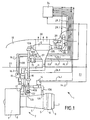
- Figure 1 schematically illustrates a supply system hot air, according to the present invention.
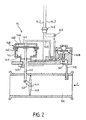
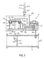
- Figures 2, 3 and 4 show, schematically in section, system regulation devices of figure 1.
- System 1 in accordance with the present invention and shown on the Figure 1, is associated with an aircraft reactor 2 from which it takes air hot to supply regulated air at a temperature and pressure desired, to installations using such air (not shown), such that for example the air conditioning installation of the cabin of said aircraft, the deicing facility for aerodynamic surfaces of this last, etc ...
- Protective fairings 8 surround the various elements above, in a manner known per se.
- System 1 includes a hot air sampling line 10, a cold air intake pipe 11, a heat exchanger precooling 12 and regulating devices 14, 15 and 16 regulating the flow of hot air and cold air circulating in the pipes 10 and 11 to supply, at the outlet of the exchanger 12, a regulated air flow in temperature and pressure.
- the hot air pipe 10 connects the compressors 4 of reactor 2 at inlet 12A of exchanger 12.
- the sampling line 10 is divided into two channels 10A and 10B separate, respectively connected to an orifice 4A disposed at the output of the high pressure stages of the compressors 4 and to an orifice 4B arranged at the outlet of the intermediate or medium pressure stages said compressors 4.
- the cold air sampling pipe 11 connects blower 3, via an air intake 17 provided in the corresponding fairing 8 downstream of the fan, with the heat exchanger 12. The latter is thus traversed transversely by the cold air coming from the blower, to cool the hot circulating air in the exchanger from its inlet 12A to its outlet 12B.
- the exchanger 12 is arranged in the mast 18 supporting the motor 2, and it a grid 20 is provided in said mast for the evacuation of cold air having traversed said exchanger 12.
- the regulating device 14, mounted on track 10A of the pipe of hot air 10 from the system, is in the form of a valve at high pressure capable of controlling the passage of hot air from the high pressure stages of the compressors 4 (port 4A) to inlet 12A of exchanger 12, through line 10.
- the valve 14 is located in nacelle 21 of reactor 2.
- On track 10B of the pipe 10 is arranged a one-way mechanical valve 22 capable to control the passage of hot air from the floors medium pressure of compressors (port 4B) to inlet 12A of the exchanger, through line 10. This valve 22 is also located in the nacelle of the reactor.
- the regulating device 15 presenting in the form of a pressure regulating valve, arranged in the mast 18 and separated, by a firewall 23, from the nacelle 21 of the reactor where valves 14 and 22 are provided.
- the regulating device 16 is arranged on the cold air pipe 11 and is also in the form of a valve transmitting air cold from the blower 3 to the heat exchanger 12.
- the valve 16 is located in the mast 18 of reactor 2, but in the hot part, between the firewall 23 and reactor 2.
- the high pressure valve 14, the control valve pressure 15 and the cold air intake valve 16 are at electrical control and they are connected, by electrical connections 14.1, 14.2 - 15.1, 15.2, 15.3 - 16.1, 16.2, to a device for centralized management 24 issuing, as required, electrical orders of operation at said valves 14, 15 and 16.
- An element 29, capable of detecting ambient overheating or the environment is also provided on the mast 18, in the vicinity of said exchanger 12 and is also connected to the management device 24 to which it address its measurements.
- the high pressure valve 14 (shown in schematic section in FIG. 2) is of the pivoting butterfly type 14A around an axis x-x (perpendicular to the plane of Figure 2) and mounted in track 10A of line 10 and is likely to close or open the passage of hot air from high pressure compressors (arrow F), towards the exchanger 12.
- the valve 14 includes a control block or actuator 14B pneumatically operated, mechanically connected to butterfly 14A and made up, like a double-acting cylinder, a 14C cylinder with the interior of which can slide, in leaktight manner, a piston 14D which actuates the butterfly 14A by means of mechanical transmission members connecting rod 14E and crankpin 14F.
- a control block or actuator 14B pneumatically operated, mechanically connected to butterfly 14A and made up, like a double-acting cylinder, a 14C cylinder with the interior of which can slide, in leaktight manner, a piston 14D which actuates the butterfly 14A by means of mechanical transmission members connecting rod 14E and crankpin 14F.
- a 14G bypass duct formed in the valve 14, connects the channel 10A, upstream of the butterfly valve 14A by relation to the direction of flow F of the hot air, with a 14H chamber of the actuator, located between the bottom 14J of the cylinder and the piston 14D.
- a return spring 14L which causes the butterfly 14A to close.
- An end contactor stroke 14M also indicates the closed / unclosed position of the valve.
- a 14N pressure reducing valve fitted with a 14P valve is arranged on the bypass 14G to deliver constant pressure in the chamber 14H of the actuator 14B and thus reduce therein, the pressure load of the hot air channel.
- the electric control of the opening and closing of the valve 14 is provided by a 14R acting solenoid (illustrated only schematically) at the 14G bypass conduit of the valve, to control the passage of hot air in the latter duct.
- Solenoid 14R and limit switch 14M are connected electrically to the management device 24, via a connector 14S, to which the electrical connections 14.1 and 14.2 are connected.
- the pressure control valve 15, shown schematically in FIG. 3, is also of the butterfly type 15A pivoting around of an axis y-y (perpendicular to the plane of Figure 3) and mounted in the line 10 to close or open the circulation of hot air towards of the exchanger 12. Its purpose is to regulate the pressure of the hot air supplied, after passing through the exchanger 12, to the installations using so as to reduce the stress for the components arranged downstream, when the sampling pressure on the engine is high.
- the valve 15 has a structure close to that of the valve 14 and it includes a pneumatic control unit or actuator 15C (or single acting cylinder), consisting of a cylinder 15D and a piston 15E provided with a flexible diaphragm 15F and extended by a rod 15G. The free end of the latter is articulated to a crank pin 15B secured to the butterfly 15A.
- a bypass 15H is provided in the valve 15 and connects the interior of the pipe 10, upstream of the butterfly 15A with respect to the direction of flow F of the hot air, with the internal chamber 15J of the actuator 15C, located between the bottom 15K of the cylinder and piston 15E with diaphragm.
- This is integrated into valve 15 and can control, depending on the position of said cam 15Q, the drop in pressure in the duct bypass 15H (via the passage 15M) and, therefore, the throttle position 15A, by modulating the air pressure transmitted in the chamber 15J of the actuator 15C.
- the 15N torque motor is connected and electrically controlled by the management device 24 in operation needs.
- the valve 15 further comprises a solenoid 15R controlling (similar to solenoid 14R) opening and closing of valve 15 by controlling the passage of hot air in the duct bypass 15H, and a limit switch 15S indicating the position valve 15 closed / not closed.
- 15N torque motor, solenoid 15R and the limit switch 15S are electrically connected to the management device 24, via a connector 15P, to which the electrical connections 15.1, 15.2 and 15.3 are connected.
- the cold air intake valve 16 disposed on the pipe 11 is shown in FIG. 4 and it is also, according to the invention, electrically controlled to operate pneumatically.
- the valve 16 is of the butterfly type 16A pivoting around an axis z-z (perpendicular to the plane of Figure 4) and it is mounted on line 11 to close or open the cold air passage coming from the blower 3.
- it includes a control block or actuator 16C pneumatically operated (or single acting cylinder) which controls the butterfly 16A via the rod 16D of a piston 16E slidably mounted in a sealed manner in the cylinder 16F of the actuator, the free end of the rod 16D being connected to the butterfly by a crankpin 16B.
- the pneumatic control of the 16C actuator is ensured, as before, by a 16G bypass conduit putting in communication one track 10E of the hot air pipe 10 of the valve regulation 15, downstream thereof, with the chamber 16H of the actuator between the piston 16E and the bottom 16J of the cylinder.
- Two end of contactors closed / unclosed stroke 16K and open / unopened 16L are linked to the actuator, while a 16M torque motor, associated with a 16Q cam, controls the section of a 16N air intake, provided in the passage of 16G bypass.
- This 16M torque motor controls the throttle position 16A between its closed and open states, by modulating the pressure addressed in the chamber 16H of the actuator 16C.
- the engine torque 16M is ventilated by a flow of cold air circulating in a tube 16P connecting the cold air line 11, upstream of the throttle valve, to the engine couple.
- a protective cover 16R surrounds it.
- the 16M torque motor and the 16K, 16L contactors are connected to the management device 24, via a 16S connector, to which the electrical connections 16.1 and 16.2 are connected.
- a return spring 16T is arranged in the chamber 16U of the actuator, opposite to the chamber 16H, to spontaneously recall the piston in the retracted position in the cylinder and thus, close the driven by the butterfly.
- the one-way valve 22 is constantly open and address, at the exchanger 12, of the hot air passing through the orifice 4B. This air pressure is limited in pressure, temperature and flow.
- the high pressure valve 14 is opened electrically by the device centralized management 24 and admits pressurized hot air through the sampling port 4A, while minimizing the sampling from high pressure compressors 4 of reactor 2.
- valve 14 is operational, i.e. when there is not enough pressure from from the valve 22, the hot air sampled, which leaves the channel 10A, then circulates in the duct 10 and is prevented from going towards the orifice 4B by the one-way valve 22.
- valve 14 The operation of the valve 14 is as follows. After excitement of the solenoid 14R by the management device 24, the bypass duct 14G opens and hot air enters the bypass 14G and enters the chamber 14H of the actuator 14B. This leads to the exit of the piston 14D and, consequently, the pivoting of the butterfly 14A from its position closed to an open position, via the rod 14E and the crankpin 14F, which opens the way 10A and allows the passage of gases hot in the direction of the control valve 15 via line 10.
- valve 14 can only open if, at the same time, the solenoid is energized by the management device 24 and a pressure exists upstream of valve 14. Indeed, if there is no pressure in upstream of the valve 14, the butterfly 14A cannot pivot, even if the duct bypass 14G is opened by the solenoid 14R. If, on the other hand, pressure exists upstream of valve 14, but that the solenoid is not excited, in particular as a result of a power cut, the duct 14G is not open and the valve 14 remains closed.
- the pressurized hot air leaving the valve 14 circulates in the line 10 and arrives in the pressure control valve 15, the activation is electrically controlled by the solenoid 15R following an order from the management device 24.
- Hot air enters in the bypass passage 15H crosses the pressure reducer 15L and goes into the 15C actuator.
- the amount of hot air at provide in the actuator room 15J as required is controlled by the 15N torque motor, which is electrically controlled by the management device 24 and which is in relation to the conduit 15H, by the passage 15M.
- the valve 15 notably reduces the stress for the components located downstream when the sampling pressure is high. If there is upstream pressure and if the 15R solenoid is energized, the control valve 15 is controlled by the torque motor. If there is no pressure in upstream or if the solenoid is de-energized, the control valve 15 is closed. We see that, for security reasons, if there is pressure in upstream, but no power supply to the torque motor, the valve 15 is closed. This operating mode guarantees that the valve 15 remains in the closed position in the event of a power cut.
- the hot air leaving the control valve 15 then flows to input 12A of the heat exchanger 12 of system 1.
- the intake valve 16 supplies cold air to the exchanger, through line 11.
- part of the hot air downstream of valve 15, enters line 10E and then into bypass 16G from valve 16 to open into the chamber 16H of actuator 16C.
- the 16M torque motor communicating with line 16G via line 16N and electrically controlled by the centralized management device 24, modulates the amount of air acting in the actuator, which causes, via piston 16E, rod 16D and crankpin 16B, pivoting desired throttle valve 16A in conduit 11.
- valve 16 If there is no pressure brought in through line 10E into the actuator, the valve 16 remains closed. This allows the closure of the valve in case of engine fire 2 (valve 16 is driven to its position completely closed thanks to a 16V thermal fuse connected to the passage 16G). With actuation pressure in the sampling line 10E downstream of valve 15, but without supply to the torque motor 16H, the inlet valve 16 is open to prevent overheating of charge in the event of a loss of electrical power. In addition, the inlet valve 16 is closed by device 24 via of the torque motor.
- a regulated air flow at determined pressure and temperature is therefore obtained and addressed to aircraft operating facilities.
- the valve 14 is then closed, and the hot air issuing orifice 4B of the compressors is addressed to the heat exchanger 12, via channel 10B, line 10 and the control valve 15. Simultaneously, cold air from cold air line 11 also flows through the heat exchanger.
- the sampling pressure is variable according to the needs of the installations users, thanks to torque motors and sensors, instead of must be set at a maximum value leading to oversizing of the system, regardless of the actual need.
- the command of the sampling temperature can also be variable instead of being set to one or two fixed values, as in known systems.
- the sampling control hot air is advantageously redundant by the 15R solenoid and the 15N torque motor.
Landscapes
- Health & Medical Sciences (AREA)
- General Health & Medical Sciences (AREA)
- Pulmonology (AREA)
- Engineering & Computer Science (AREA)
- Aviation & Aerospace Engineering (AREA)
- Fluid-Pressure Circuits (AREA)
- Control Of Positive-Displacement Air Blowers (AREA)
- Flow Control (AREA)
Claims (9)
- Warmluftversorgungseinrichtung für ein mit mindestens einem Motor (2) mit Gebläse (3) und Kompressoren (4) ausgestattetes Flugzeug, das folgendes umfasst:dadurch gekennzeichnet,eine erste Leitung (10), die an den genannten Kompressoren (4) warme Druckluft entnimmt und an der ein Durchflussmengenregelventil (14) und ein Druckregelventil (15) montiert sind, wobei die genannten Ventile jeweils ein gesteuertes Organ (14A oder 15A) umfassen, das das Einströmen der Warmluft in die genannte erste Leitung kontrollieren kann;eine zweite Leitung (11), die kalte Druckluft am genannten Gebläse (3) entnimmt und an der ein Durchflussmengenregelventil (16) montiert ist, wobei das genannte Ventil ein gesteuertes Organ (16A) umfasst, das das Einströmen der Kaltluft in die genannte zweite Leitung kontrollieren kann;einen Vorkühlwärmetauscher (12), an den die genannte erste und zweite Leitung (10 und 11) angeschlossen sind;einen Lufttemperaturfühler (28), der am Ausgang des genannten Wärmetauschers (12) angeordnet ist;einen Luftdruckfühler (27), der an der genannten ersten Warmluftentnahmeleitung (10) angeordnet ist;eine Kontrollvorrichtung (24), die elektrische Signale erhält, die repräsentativ für die Messungen des genannten Temperaturfühlers (28) und des genannten Druckfühlers (27) sind, und die das genannte Warmluftdurchflussmengenregelventil (14) steuert,dass das genannte Warmluftdurchflussmengenregelventil (14), das genannte Warmluftdruckregelventil (15) und das genannte Kaltluftdruckregelventil (16) jeweils einen Steuerblock (14B, 15C, 16C) umfassen, der das entsprechende gesteuerte Organ (14A, 15A, 16A) kontrollieren kann;dass jeder der genannten Steuerblöcke (14B, 15C, 16C) elektrisch kontrollierte Mittel umfasst, die Druckluft an der genannten ersten und zweiten Leitung (10, 11) entnehmen können, um das entsprechende gesteuerte Organ (14A, 15A, 16A) pneumatisch zu betätigen; unddass die genannte Kontrollvorrichtung (24) außer dem genannten Warmluftdurchflussmengenregelventil (14) das genannte Warmluftdruckregelventil (15) und das genannte Kaltluftdruckregelventil (16) steuert und so die Zentralsteuerung des genannten Systems gewährleistet.
- Einrichtung gemäß Anspruch 1,
dadurch gekennzeichnet, dass jeder der genannten Steuerblöcke (14B, 15C, 16C) mit dem entsprechenden gesteuerten Organ (14A, 15A, 16A) eine Baugruppe bildet. - Einrichtung gemäß Anspruch 1 oder 2,
dadurch gekennzeichnet, dass der genannte Warmluftdruckfühler (27) zwischen dem Druckregelventil (15) und dem Wärmetauscher (12) installiert ist. - Einrichtung gemäß einem der Ansprüche 1 bis 3, in dem die erste Warmluftentnahmeleitung (10) auf der Seite der genannten Kompressoren (4) zwei getrennte Leitungen (10A, 10B) umfasst, von denen eine (10A) (bei 4A) mit den Hochdruckstufen der genannten Kompressoren (4) verbunden ist und das genannte Warmluftmengenregelventil (14) umfasst, und die andere (10B) (bei 4B) mit den Mitteldruckstufen der genannten Kompressoren (4) verbunden ist und ein mechanisches Einrichtungsventil (22) umfasst,
dadurch gekennzeichnet, dass es einen zusätzlichen Luftdruckfühler (26) umfasst, der am genannten anderen Abzweig (10B) der genannten ersten Warmluftentnahmeleitung (10) zwischen dem genannten mechanischen Einrichtungsventil (22) und den genannten Mitteldruckstufen der genannten Kompressoren (4) angeordnet ist, wobei der genannte zusätzliche Luftdruckfühler (26) elektrische Signale, die repräsentativ für seine Messungen sind, an die genannte Kontrollvorrichtung (24) sendet. - Einrichtung gemäß einem der Ansprüche 1 bis 4,
dadurch gekennzeichnet, dass das gesteuerte Organ des genannten Warmluftdurchflussmengenregelventils (14) eine drehbar gelagerte Ventilklappe (14A) ist, die in der ersten Leitung (10) in Nähe des Ausgangs (4A) der Hochdruckstufen der genannten Kompressoren (4) angeordnet ist, und dadurch, dass der Steuerblock des genannten Warmluftdurchflussmengenregelventils (14) folgendes umfasst:ein pneumatisches Betätigungselement (14B), das mechanisch mit der genannten Ventilklappe (14A) zu deren Drehung verbunden ist;eine Abzweigleitung (14G), die das genannte Betätigungselement (14B) vor der genannten Ventilklappe (14A) mit der genannten ersten Leitung (10) verbindet; undein elektrisches Betätigungselement (14R), das elektrisch mit der genannten Kontrollvorrichtung (24) verbunden ist und das Einströmen der Warmluft in die genannte Abzweigleitung (14G) steuert. - Einrichtung gemäß einem der vorstehenden Ansprüche 1 bis 5,
dadurch gekennzeichnet, dass das gesteuerte Organ des genannten Warmluftdruckregelventils (15) eine drehbar gelagerte Ventilklappe (15A) ist, die in der genannten ersten Warmluftleitung (10) angeordnet ist, und dadurch, dass der Steuerblock des genannten Warmluftdruckregelventils (15) folgendes umfasst:ein pneumatisches Betätigungsorgan (15C), das mechanisch mit der genannten Ventilklappe (15A) zu deren Drehung verbunden ist;eine Abzweigleitung (15H), die das genannte Betätigungselement (15C) vor der genannten Ventilklappe (15A) mit der genannten ersten Leitung verbindet; undein elektrisches Betätigungselement (15R), das elektrisch mit der genannten Kontrollvorrichtung (24) verbunden ist und das Einströmen der Warmluft in die genannte Abzweigleitung (15H) steuert; undModulationsmittel (15N), die elektrisch durch die genannte Kontrollvorrichtung (24) gesteuert werden und die durch die genannte Abzweigleitung (15H) zum genannten Betätigungselement geleitete Warmluftmenge modulieren. - Einrichtung gemäß Anspruch 5 oder 6,
dadurch gekennzeichnet, dass das genannte Regelventil (14, 15) mit drehbar gelagerter Ventilklappe (14A, 15A) einen Druckminderer (14N, 15L) umfasst, der an der genannten Abzweigleitung (14G, 15H) installiert ist. - Einrichtung gemäß einem der vorstehenden Ansprüche 1 bis 7,
dadurch gekennzeichnet, dass das gesteuerte Organ des genannten Kaltluftdurchflussmengenregelventils (16) eine drehbar gelagerte Ventilklappe (16A) ist, die in der genannten zweiten Kaltluftleitung (11) angeordnet ist, und dadurch, dass der Steuerblock des genannten Kaltluftdurchflussmengenregelventils (10) folgendes umfasst:ein pneumatisches Betätigungsorgan (16C), das mechanisch mit der genannten Ventilklappe (16A) zu deren Drehung verbunden ist;eine Abzweigleitung (16G), die das genannte Betätigungselement (16C) hinter dem genannten Warmluftdruckregelventil (15) mit der genannten ersten Warmtuftleitung (10) verbindet; undModulationsmittel (16M), die elektrisch durch die genannte Kontrollvorrichtung (24) gesteuert werden und die durch die genannte Abzweigleitung (16G) zum genannten Betätigungselement geleitete Kaltluftmenge modulieren. - Einrichtung gemäß Anspruch 8,
dadurch gekennzeichnet, dass eine Leitung (16P) die genannte zweite Kattluftentnahmeleitung (11) vor der drehbar gelagerten Ventilklappe (16A) mit den genannten Modulationsmitteln (16M) verbindet, um deren Kühlung zu gewährleisten.
Applications Claiming Priority (2)
| Application Number | Priority Date | Filing Date | Title |
|---|---|---|---|
| FR9801351A FR2774357B1 (fr) | 1998-02-05 | 1998-02-05 | Systeme d'alimentation en air chaud pour aeronef |
| FR9801351 | 1998-02-05 |
Publications (2)
| Publication Number | Publication Date |
|---|---|
| EP0934876A1 EP0934876A1 (de) | 1999-08-11 |
| EP0934876B1 true EP0934876B1 (de) | 2003-07-02 |
Family
ID=9522632
Family Applications (1)
| Application Number | Title | Priority Date | Filing Date |
|---|---|---|---|
| EP99400216A Expired - Lifetime EP0934876B1 (de) | 1998-02-05 | 1999-02-01 | Warmluftversorgungseinrichtung für Flugzeug |
Country Status (5)
| Country | Link |
|---|---|
| US (1) | US6058725A (de) |
| EP (1) | EP0934876B1 (de) |
| CA (1) | CA2261364C (de) |
| DE (1) | DE69909149T2 (de) |
| FR (1) | FR2774357B1 (de) |
Families Citing this family (38)
| Publication number | Priority date | Publication date | Assignee | Title |
|---|---|---|---|---|
| US6694746B2 (en) * | 2002-02-06 | 2004-02-24 | Honeywell International, Inc. | Micro volume actuator for an air turbine starter |
| US6782701B2 (en) * | 2003-01-22 | 2004-08-31 | Honeywell International Inc. | Master-slave engine bleed flow sharing control method and system |
| DE10361655B4 (de) * | 2003-12-30 | 2007-10-04 | Airbus Deutschland Gmbh | Vorrichtung und Verfahren zur Fußbodenheizung in einem Flugzeug |
| US7536865B2 (en) * | 2005-02-09 | 2009-05-26 | Honeywell International Inc. | Method and system for balancing bleed flows from gas turbine engines |
| DE102006023498B4 (de) * | 2006-05-18 | 2010-02-25 | Airbus Deutschland Gmbh | Zapfluftzufuhrsystem eines Flugzeuges mit einer Schaltanordnung zum Schutz des Zapfluftzufuhrsystems vor Überhitzung |
| DE102006050869A1 (de) | 2006-10-27 | 2008-04-30 | Airbus Deutschland Gmbh | Schalldämpfungseinrichtung für eine Luftrohrleitung eines Flugzeuges, insbesondere bei einer Flugzeugklimaanlage |
| FR2911580B1 (fr) * | 2007-01-22 | 2009-02-27 | Airbus France Sas | Systeme de conditionnement d'air pour aeronef |
| DE102010021890A1 (de) * | 2010-05-28 | 2011-12-01 | Airbus Operations Gmbh | Klimatisierungssystem für ein Flugzeug mit Hybrid-Betrieb |
| US20120045317A1 (en) * | 2010-08-23 | 2012-02-23 | Honeywell International Inc. | Fuel actuated bleed air system |
| US8661833B2 (en) * | 2011-01-14 | 2014-03-04 | Hamilton Sundstrand Corporation | Bleed valve module |
| US9670842B2 (en) * | 2011-01-14 | 2017-06-06 | Hamilton Sundstrand Corporation | Bleed valve module with position feedback and cooling shroud |
| US8397487B2 (en) * | 2011-02-28 | 2013-03-19 | General Electric Company | Environmental control system supply precooler bypass |
| FR2976255B1 (fr) * | 2011-06-09 | 2013-12-20 | Snecma | Dispositif de controle d'un systeme de prelevement d'air d'un aeronef |
| FR2978123B1 (fr) * | 2011-07-18 | 2013-08-23 | Snecma | Systeme de controle et de surveillance d'un aeronef |
| US10830133B2 (en) | 2013-09-03 | 2020-11-10 | Hamilton Sundstrand Corporation | Aircraft environmental control system selectively powered by three bleed ports |
| US9957051B2 (en) | 2013-09-03 | 2018-05-01 | Hamilton Sundstrand Corporation | Method of operating a multi-pack environmental control system |
| US9382841B2 (en) | 2013-09-03 | 2016-07-05 | Hamilton Sundstrand Corporation | Aircraft environmental control system selectively powered by three bleed ports |
| FR3017656B1 (fr) * | 2014-02-17 | 2016-03-11 | Airbus Operations Sas | Turboreacteur comportant un systeme de prelevement destine a prelever de l'air dans ledit turboreacteur |
| CN105667810B (zh) * | 2014-11-19 | 2018-01-16 | 中国航空工业集团公司西安飞机设计研究所 | 一种多发引气系统流量平衡控制方法 |
| US10100733B2 (en) * | 2015-07-31 | 2018-10-16 | Ge Aviation Systems Llc | Turbine engine with anti-ice valve assembly, bleed air valve, and method of operating |
| US20170067578A1 (en) * | 2015-09-09 | 2017-03-09 | Honeywell International Inc. | Detection of high stage valve leakage by pressure lockup |
| EP3254970B1 (de) * | 2016-05-26 | 2020-04-29 | Hamilton Sundstrand Corporation | Klimaregelungssystem mit einem abströmungswärmetauscher |
| US11511867B2 (en) | 2016-05-26 | 2022-11-29 | Hamilton Sundstrand Corporation | Mixing ram and bleed air in a dual entry turbine system |
| US11506121B2 (en) | 2016-05-26 | 2022-11-22 | Hamilton Sundstrand Corporation | Multiple nozzle configurations for a turbine of an environmental control system |
| EP3249196B1 (de) | 2016-05-26 | 2020-12-02 | Hamilton Sundstrand Corporation | Energiefluss eines fortschrittlichen klimaregelungssystems |
| US10669945B2 (en) * | 2017-02-06 | 2020-06-02 | Raytheon Technologies Corporation | Starter air valve system with dual electromechanical controls |
| EP3409988B1 (de) | 2017-05-31 | 2020-04-01 | Hamilton Sundstrand Corporation | Pneumatisches servoventil mit einstellbaren dosierelementen |
| EP3409987B1 (de) | 2017-05-31 | 2020-11-04 | Hamilton Sundstrand Corporation | Federabgedichtetes pneumatisches servoventil |
| EP3409989B1 (de) | 2017-05-31 | 2021-09-15 | Hamilton Sundstrand Corporation | Pneumatisches servoventil mit einstellbarer antriebseinheit |
| FR3070057B1 (fr) | 2017-08-11 | 2019-09-06 | Safran Aircraft Engines | Unite de commande d'une vanne commandee de prelevement d'un flux d'air dans un flux d'air sous pression d'un aeronef |
| FR3080901B1 (fr) * | 2018-05-04 | 2021-02-12 | Liebherr Aerospace Toulouse Sas | Vanne de regulation d'un flux de fluide et systeme de prelevement d'air d'un aeronef equipe d'une telle vanne |
| US11130583B2 (en) * | 2018-11-02 | 2021-09-28 | Rohr, Inc. | Control system for aircraft anti-icing |
| EP3708493B1 (de) * | 2019-03-11 | 2021-11-10 | Airbus SAS | Flugzeugantriebssystem mit einem wärmetauschersystem |
| EP3708495B1 (de) * | 2019-03-11 | 2021-11-17 | Airbus SAS | Flugzeugantriebssystem mit einem wärmetauschersystem |
| EP3708494B1 (de) * | 2019-03-11 | 2021-11-17 | Airbus SAS | Flugzeugantriebssystem mit einem wärmetauschersystem |
| US11260978B2 (en) * | 2019-05-03 | 2022-03-01 | Pratt & Whitney Canada Corp. | Valve for aircraft environmental control system conduit |
| FR3097963B1 (fr) * | 2019-06-27 | 2021-06-04 | Liebherr Aerospace Toulouse Sas | Surveillance de l’état d’un échangeur dans un circuit d’air d’un aéronef |
| US20260085639A1 (en) * | 2024-09-23 | 2026-03-26 | Honeywell International Inc. | Gas Turbine Engine Inlet Anti-Ice System |
Family Cites Families (10)
| Publication number | Priority date | Publication date | Assignee | Title |
|---|---|---|---|---|
| FR337830A (fr) * | 1903-12-18 | 1904-04-29 | Louis Charles Maximilien Balbr | Système de jumelle à écartement variable |
| US2562918A (en) * | 1949-02-09 | 1951-08-07 | William M Hynes | Aircraft cabin air conditioning system and control valve therefor |
| US2917288A (en) * | 1954-11-26 | 1959-12-15 | United Aircraft Corp | Cabin temperature control system |
| US3878692A (en) * | 1974-04-22 | 1975-04-22 | Garrett Corp | Aircraft cabin cooling method and apparatus |
| US4285466A (en) * | 1980-02-25 | 1981-08-25 | The Boeing Co. | Apparatus for mixing high and low pressure air from a jet engine |
| US4671318A (en) * | 1985-02-08 | 1987-06-09 | The Garrett Corporation | Aircraft engine bleed air flow balancing technique |
| US4617958A (en) * | 1985-07-25 | 1986-10-21 | Sundstrand Corporation | Control valve |
| FR2628860B1 (fr) * | 1988-03-17 | 1992-06-05 | Abg Semca | Dispositif d'equilibrage de debit, dispositif de climatisation d'aeronef comportant ledit dispositif d'equilibrage et aeronef comportant ledit dispositif de climatisation |
| US5155991A (en) * | 1991-04-01 | 1992-10-20 | United Technologies Corporation | Bleed air flow regulators with flow balance |
| US5161364A (en) * | 1991-04-01 | 1992-11-10 | United Technologies Corporation | Control of aircraft bleed air stage mixing |
-
1998
- 1998-02-05 FR FR9801351A patent/FR2774357B1/fr not_active Expired - Lifetime
-
1999
- 1999-02-01 DE DE69909149T patent/DE69909149T2/de not_active Expired - Lifetime
- 1999-02-01 EP EP99400216A patent/EP0934876B1/de not_active Expired - Lifetime
- 1999-02-02 CA CA002261364A patent/CA2261364C/fr not_active Expired - Lifetime
- 1999-02-04 US US09/244,434 patent/US6058725A/en not_active Expired - Lifetime
Also Published As
| Publication number | Publication date |
|---|---|
| DE69909149T2 (de) | 2004-04-08 |
| CA2261364C (fr) | 2006-11-14 |
| DE69909149D1 (de) | 2003-08-07 |
| US6058725A (en) | 2000-05-09 |
| EP0934876A1 (de) | 1999-08-11 |
| FR2774357B1 (fr) | 2000-04-07 |
| CA2261364A1 (fr) | 1999-08-05 |
| FR2774357A1 (fr) | 1999-08-06 |
Similar Documents
| Publication | Publication Date | Title |
|---|---|---|
| CA2261364C (fr) | Systeme d'alimentation en air chaud pour aeronef | |
| EP3013689B1 (de) | Enteisungs- und konditionierungsvorrichtung für ein flugzeug | |
| CA2929951C (fr) | Ensemble propulsif d'aeronef avec systeme d'extinction de feu | |
| EP3665376B1 (de) | Einheit zur steuerung eines gesteuerten ventils zur entnahme eines luftstroms aus einem druckluftstrom eines flugzeuges | |
| FR2829464A1 (fr) | Procede et dispositif de conditionnement d'air de cabine d'aeronef | |
| FR3009278A1 (fr) | Procede de regulation du degivrage d'un bord d'attaque d'un aeronef et dispositif pour sa mise en oeuvre | |
| EP0501854A1 (de) | Krafwagenkühler mit Fluidumzirkulationssteuereinrichtung | |
| FR2606898A1 (fr) | Appareil de commande d'une vanne de regulation de pression, notamment pour une installation de conditionnement d'air d'une cabine d'avion | |
| CA2611556C (fr) | Systeme de commande pour nacelle de turboreacteur | |
| FR2834533A1 (fr) | Dispositif de refroidissement de la tuyere commune sur une nacelle | |
| EP0646702B1 (de) | Verfahren und Vorrichtung zur Regelung des Durchflusses durch ein Verzweigergehäuse und mit solch einer Vorrichtung ausgerüstetes System zur Regelung der Ladeluft einer Brennkraftmaschine | |
| CA2687939A1 (fr) | Trompe de melange de gaz a section d'injection variable | |
| FR3081514A1 (fr) | Ensemble propulsif d'aeronef et procede de reduction d'un debit d'air de ventilation dans l'ensemble propulsif d'aeronef | |
| FR2859239A1 (fr) | Dispositif de regulation thermique de gaz d'echappement | |
| FR2982319A1 (fr) | Systeme de commande d'une vanne pneumatique de turbomachine | |
| EP3342709A1 (de) | Verfahren und anlage zur klimatisierung eines luftfahrzeugs, das mit zapfluft mit zwischendruck versorgt wird | |
| FR2743027A1 (fr) | Dispositif de climatisation de l'habitacle d'un vehicule | |
| FR2720442A1 (fr) | Installation d'alimentation en carburant d'un turboréacteur. | |
| EP3466816B1 (de) | Autonomes modul zur energierückgewinnung einer kabine eines luftfahrzeugs, und entsprechendes verfahren | |
| FR2503056A1 (fr) | Installation de ventilation de vehicule | |
| FR3128506A1 (fr) | Système de pilotage de distribution de fluide dans un circuit hydraulique | |
| FR2564143A1 (fr) | Generateur de gaz chauds du type auto-entretenu avec commande des etapes de fonctionnement | |
| FR3003544A1 (fr) | Dispositif de surveillance et de coupure de l'alimentation en air de pressurisation d'un reservoir de carburant d'aeronef | |
| FR3135965A1 (fr) | Ensemble propulsif amélioré pour aéronef multi moteurs | |
| FR2859238A1 (fr) | Dispositif de regulation thermique de gaz d'echappement |
Legal Events
| Date | Code | Title | Description |
|---|---|---|---|
| PUAI | Public reference made under article 153(3) epc to a published international application that has entered the european phase |
Free format text: ORIGINAL CODE: 0009012 |
|
| AK | Designated contracting states |
Kind code of ref document: A1 Designated state(s): DE GB |
|
| AX | Request for extension of the european patent |
Free format text: AL;LT;LV;MK;RO;SI |
|
| 17P | Request for examination filed |
Effective date: 19990910 |
|
| AKX | Designation fees paid |
Free format text: DE GB |
|
| RAP1 | Party data changed (applicant data changed or rights of an application transferred) |
Owner name: LIEBHERR-AEROSPACE TOULOUSE S.A. Owner name: AEROSPATIALE MATRA |
|
| GRAH | Despatch of communication of intention to grant a patent |
Free format text: ORIGINAL CODE: EPIDOS IGRA |
|
| GRAH | Despatch of communication of intention to grant a patent |
Free format text: ORIGINAL CODE: EPIDOS IGRA |
|
| GRAA | (expected) grant |
Free format text: ORIGINAL CODE: 0009210 |
|
| RAP1 | Party data changed (applicant data changed or rights of an application transferred) |
Owner name: LIEBHERR-AEROSPACE TOULOUSE S.A. Owner name: AIRBUS FRANCE |
|
| AK | Designated contracting states |
Designated state(s): DE GB |
|
| REG | Reference to a national code |
Ref country code: GB Ref legal event code: FG4D Free format text: NOT ENGLISH |
|
| GBT | Gb: translation of ep patent filed (gb section 77(6)(a)/1977) | ||
| REF | Corresponds to: |
Ref document number: 69909149 Country of ref document: DE Date of ref document: 20030807 Kind code of ref document: P |
|
| PLBE | No opposition filed within time limit |
Free format text: ORIGINAL CODE: 0009261 |
|
| STAA | Information on the status of an ep patent application or granted ep patent |
Free format text: STATUS: NO OPPOSITION FILED WITHIN TIME LIMIT |
|
| 26N | No opposition filed |
Effective date: 20040405 |
|
| REG | Reference to a national code |
Ref country code: GB Ref legal event code: 732E Free format text: REGISTERED BETWEEN 20110721 AND 20110727 |
|
| REG | Reference to a national code |
Ref country code: DE Ref legal event code: R082 Ref document number: 69909149 Country of ref document: DE Representative=s name: MEISSNER & MEISSNER, DE |
|
| REG | Reference to a national code |
Ref country code: DE Ref legal event code: R082 Ref document number: 69909149 Country of ref document: DE Representative=s name: ANWALTSKANZLEI MEISSNER & MEISSNER, DE Effective date: 20120509 Ref country code: DE Ref legal event code: R082 Ref document number: 69909149 Country of ref document: DE Representative=s name: MEISSNER & MEISSNER, DE Effective date: 20120509 Ref country code: DE Ref legal event code: R081 Ref document number: 69909149 Country of ref document: DE Owner name: AIRBUS OPERATIONS SAS, FR Free format text: FORMER OWNERS: AIRBUS FRANCE, TOULOUSE, FR; LIEBHERR-AEROSPACE TOULOUSE S.A., TOULOUSE, FR Effective date: 20120509 Ref country code: DE Ref legal event code: R081 Ref document number: 69909149 Country of ref document: DE Owner name: LIEBHERR-AEROSPACE TOULOUSE S.A., FR Free format text: FORMER OWNERS: AIRBUS FRANCE, TOULOUSE, FR; LIEBHERR-AEROSPACE TOULOUSE S.A., TOULOUSE, FR Effective date: 20120509 Ref country code: DE Ref legal event code: R081 Ref document number: 69909149 Country of ref document: DE Owner name: AIRBUS OPERATIONS SAS, FR Free format text: FORMER OWNER: AIRBUS FRANCE, LIEBHERR-AEROSPACE TOULOUSE S.A, , FR Effective date: 20120509 Ref country code: DE Ref legal event code: R081 Ref document number: 69909149 Country of ref document: DE Owner name: LIEBHERR-AEROSPACE TOULOUSE S.A., FR Free format text: FORMER OWNER: AIRBUS FRANCE, LIEBHERR-AEROSPACE TOULOUSE S.A, , FR Effective date: 20120509 |
|
| PGFP | Annual fee paid to national office [announced via postgrant information from national office to epo] |
Ref country code: GB Payment date: 20180216 Year of fee payment: 20 Ref country code: DE Payment date: 20180219 Year of fee payment: 20 |
|
| REG | Reference to a national code |
Ref country code: DE Ref legal event code: R071 Ref document number: 69909149 Country of ref document: DE |
|
| REG | Reference to a national code |
Ref country code: GB Ref legal event code: PE20 Expiry date: 20190131 |
|
| PG25 | Lapsed in a contracting state [announced via postgrant information from national office to epo] |
Ref country code: GB Free format text: LAPSE BECAUSE OF EXPIRATION OF PROTECTION Effective date: 20190131 |