EP0934876A1 - Système d'alimentation en air chaud pour aéronef - Google Patents
Système d'alimentation en air chaud pour aéronef Download PDFInfo
- Publication number
- EP0934876A1 EP0934876A1 EP99400216A EP99400216A EP0934876A1 EP 0934876 A1 EP0934876 A1 EP 0934876A1 EP 99400216 A EP99400216 A EP 99400216A EP 99400216 A EP99400216 A EP 99400216A EP 0934876 A1 EP0934876 A1 EP 0934876A1
- Authority
- EP
- European Patent Office
- Prior art keywords
- valve
- hot air
- pressure
- regulating
- air
- Prior art date
- Legal status (The legal status is an assumption and is not a legal conclusion. Google has not performed a legal analysis and makes no representation as to the accuracy of the status listed.)
- Granted
Links
- 230000001105 regulatory effect Effects 0.000 claims description 30
- 238000005070 sampling Methods 0.000 claims description 20
- 238000011144 upstream manufacturing Methods 0.000 claims description 17
- 230000001276 controlling effect Effects 0.000 claims description 15
- 238000004891 communication Methods 0.000 claims description 12
- 230000006854 communication Effects 0.000 claims description 12
- 238000005259 measurement Methods 0.000 claims description 8
- 210000000056 organ Anatomy 0.000 claims description 3
- 238000010276 construction Methods 0.000 claims description 2
- 238000001816 cooling Methods 0.000 claims description 2
- 238000002485 combustion reaction Methods 0.000 abstract description 3
- 238000007726 management method Methods 0.000 description 17
- 238000012550 audit Methods 0.000 description 8
- 238000012423 maintenance Methods 0.000 description 7
- 235000001954 papillon Nutrition 0.000 description 5
- 244000229285 papillon Species 0.000 description 5
- 230000033228 biological regulation Effects 0.000 description 4
- 239000003638 chemical reducing agent Substances 0.000 description 4
- 238000013024 troubleshooting Methods 0.000 description 3
- 238000004378 air conditioning Methods 0.000 description 2
- 230000009975 flexible effect Effects 0.000 description 2
- 239000007789 gas Substances 0.000 description 2
- 238000013021 overheating Methods 0.000 description 2
- 230000001681 protective effect Effects 0.000 description 2
- 238000012546 transfer Methods 0.000 description 2
- 230000004913 activation Effects 0.000 description 1
- 230000004087 circulation Effects 0.000 description 1
- 239000000470 constituent Substances 0.000 description 1
- 238000009795 derivation Methods 0.000 description 1
- 238000006073 displacement reaction Methods 0.000 description 1
- 229940082150 encore Drugs 0.000 description 1
- 235000021183 entrée Nutrition 0.000 description 1
- 238000007689 inspection Methods 0.000 description 1
- 238000009434 installation Methods 0.000 description 1
- 230000009347 mechanical transmission Effects 0.000 description 1
- 230000009467 reduction Effects 0.000 description 1
- 230000008093 supporting effect Effects 0.000 description 1
- 238000010257 thawing Methods 0.000 description 1
Images

Classifications
-
- B—PERFORMING OPERATIONS; TRANSPORTING
- B64—AIRCRAFT; AVIATION; COSMONAUTICS
- B64D—EQUIPMENT FOR FITTING IN OR TO AIRCRAFT; FLIGHT SUITS; PARACHUTES; ARRANGEMENT OR MOUNTING OF POWER PLANTS OR PROPULSION TRANSMISSIONS IN AIRCRAFT
- B64D13/00—Arrangements or adaptations of air-treatment apparatus for aircraft crew or passengers, or freight space
- B64D13/02—Arrangements or adaptations of air-treatment apparatus for aircraft crew or passengers, or freight space the air being pressurised
- B64D13/04—Automatic control of pressure
-
- B—PERFORMING OPERATIONS; TRANSPORTING
- B64—AIRCRAFT; AVIATION; COSMONAUTICS
- B64D—EQUIPMENT FOR FITTING IN OR TO AIRCRAFT; FLIGHT SUITS; PARACHUTES; ARRANGEMENT OR MOUNTING OF POWER PLANTS OR PROPULSION TRANSMISSIONS IN AIRCRAFT
- B64D13/00—Arrangements or adaptations of air-treatment apparatus for aircraft crew or passengers, or freight space
- B64D13/02—Arrangements or adaptations of air-treatment apparatus for aircraft crew or passengers, or freight space the air being pressurised
Definitions
- the present invention relates to an air supply system hot for aircraft.
- the object of the present invention is to remedy these drawbacks.
- each of said control blocks forms a building unit with the corresponding controlled organ, said construction unit can therefore be arranged in the vicinity of one or other of the first and second air lines.
- said hot air pressure detector is mounted between the pressure control valve and the heat exchanger.
- said system comprises an additional air pressure sensor disposed on said other branch of said first hot air sampling pipe, between said one-way mechanical valve and said intermediate pressure stages said compressors, said additional air pressure sensor addressing electrical signals representative of its measurements audit control system.
- Said hot air flow and pressure regulating valves may include a pressure reducer mounted on said conduit derivation.
- a duct can connect said second cold air sampling line, upstream of the pivoting butterfly, to said modulation means to ensure the cooling.
- the three control valves are electrically controlled, operate pneumatically, and the amounts of circulating air in the high pressure valve and in the cold air intake valve can advantageously be modulated as needed by said modulating means, to optimize the performance of the power system in hot air, in accordance with the present invention.
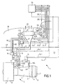
- Figure 1 schematically illustrates a supply system hot air, in accordance with the present invention.
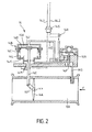
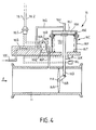
- Figures 2, 3 and 4 show, schematically in section, system regulation devices of figure 1.
- System 1 in accordance with the present invention and shown on the Figure 1, is associated with an aircraft reactor 2 from which it takes air hot to supply regulated air at temperature and pressure desired, to installations using such air (not shown), such that for example the air conditioning installation of the cabin of said aircraft, the deicing facility for aerodynamic surfaces of this last, etc ...
- Protective fairings 8 surround the various elements above, in a manner known per se.
- System 1 includes a hot air sampling line 10, a cold air intake pipe 11, a heat exchanger precooling 12 and regulating devices 14, 15 and 16 regulating the flow of hot air and cold air circulating in the pipes 10 and 11 to supply, at the outlet of the exchanger 12, a regulated air flow in temperature and pressure.
- the hot air line 10 connects the compressors 4 of reactor 2 at inlet 12A of exchanger 12.
- the sampling line 10 is divided into two channels 10A and 10B separate, respectively connected to an orifice 4A disposed at the output of the high pressure stages of the compressors 4 and to an orifice 4B arranged at the outlet of the intermediate or medium pressure stages said compressors 4.
- the cold air sampling pipe 11 connects blower 3 via an air intake 17 provided in the corresponding fairing 8 downstream of the fan, with the heat exchanger 12. The latter is thus traversed transversely by cold air from the blower, to cool the hot circulating air in the exchanger from its inlet 12A to its outlet 12B.
- the exchanger 12 is arranged in the mast 18 supporting the motor 2, and it a grid 20 is provided in said mast for the evacuation of cold air having traversed said exchanger 12.
- the regulating device 14, mounted on track 10A of the pipe of hot air 10 from the system, is in the form of a valve at high pressure capable of controlling the passage of hot air from the high pressure stages of the compressors 4 (port 4A) to inlet 12A of exchanger 12, through line 10.
- the valve 14 is located in nacelle 21 of reactor 2.
- On track 10B of the pipe 10 is arranged a unidirectional mechanical valve 22 capable to control the passage of hot air from the floors medium pressure of the compressors (port 4B) to inlet 12A of the exchanger, through line 10. This valve 22 is also located in the reactor nacelle.
- the regulating device 15 presenting in the form of a pressure regulating valve, arranged in the mast 18 and separated, by a firewall 23, from the nacelle 21 of the reactor where valves 14 and 22 are provided.
- the regulating device 16 is arranged on the cold air pipe 11 and is also in the form of a valve transmitting air cold from blower 3 to heat exchanger 12. Valve 16 is located in the mast 18 of reactor 2, but in the hot part, between the firewall 23 and reactor 2.
- the high pressure valve 14, the control valve pressure 15 and the cold air intake valve 16 are at electrical control and they are connected, by electrical connections 14.1, 14.2 - 15.1, 15.2, 15.3 - 16.1, 16.2, to a device for centralized management 24 issuing, as required, electrical orders of operation at said valves 14, 15 and 16.
- An element 29, capable of detecting ambient overheating or the environment is also provided on the mast 18, in the vicinity of said exchanger 12 and is also connected to the management device 24 to which it address its measurements.
- the high pressure valve 14 (shown in schematic section in FIG. 2) is of the pivoting butterfly type 14A around an axis x-x (perpendicular to the plane of Figure 2) and mounted in track 10A of line 10 and is likely to close or open the passage of hot air from high pressure compressors (arrow F), towards the exchanger 12.
- the valve 14 includes a control block or actuator 14B pneumatically operated, mechanically connected to butterfly 14A and made up, like a double-acting cylinder, a 14C cylinder with the interior of which can slide, in leaktight manner, a piston 14D which actuates the butterfly 14A by means of mechanical transmission members connecting rod 14E and crankpin 14F.
- a control block or actuator 14B pneumatically operated, mechanically connected to butterfly 14A and made up, like a double-acting cylinder, a 14C cylinder with the interior of which can slide, in leaktight manner, a piston 14D which actuates the butterfly 14A by means of mechanical transmission members connecting rod 14E and crankpin 14F.
- a 14G bypass conduit formed in the valve 14, connects the channel 10A, upstream of the butterfly valve 14A by relation to the direction of flow F of the hot air, with a 14H chamber of the actuator, located between the bottom 14J of the cylinder and the piston 14D.
- a return spring 14L which causes the butterfly 14A to close.
- An end contactor stroke 14M also indicates the closed / not closed position of the valve.
- a 14N pressure reducer fitted with a 14P valve is arranged on the bypass duct 14G to deliver constant pressure in the chamber 14H of the actuator 14B and thus reduce therein, the pressure load of the hot air channel.
- the electric control of the opening and closing of the valve 14 is provided by a 14R acting solenoid (as illustrated only schematically) at the 14G bypass conduit of the valve, to control the passage of hot air in this latter duct.
- the 14R solenoid and the 14M limit switch are connected electrically to the management device 24, via a connector 14S, to which the electrical connections 14.1 and 14.2 are connected.
- the pressure control valve 15, shown schematically in FIG. 3, is also of the butterfly type 15A pivoting around a y-y axis (perpendicular to the plane of Figure 3) and mounted in the line 10 to close or open the circulation of hot air towards of the exchanger 12. Its purpose is to regulate the pressure of the hot air supplied, after passing through the exchanger 12, to the installations using so as to reduce the stress for the components arranged downstream, when the sampling pressure on the engine is high.
- the valve 15 has a structure close to that of the valve 14 and it includes a pneumatic control block or actuator 15C (or single acting cylinder), consisting of a cylinder 15D and a piston 15E provided with a flexible diaphragm 15F and extended by a rod 15G. The free end of the latter is articulated to a crank pin 15B secured to the butterfly 15A.
- a bypass 15H is provided in the valve 15 and connects the interior of the pipe 10, upstream of the butterfly 15A with respect to the direction of flow F of the hot air, with the internal chamber 15J of the actuator 15C, located between the bottom 15K of the cylinder and piston 15E with diaphragm.
- This is integrated into valve 15 and can control, depending on the position of said cam 15Q, the pressure drop in the duct bypass 15H (via passage 15M) and, therefore, the throttle position 15A, by modulating the air pressure transmitted in the chamber 15J of the actuator 15C.
- the 15N torque motor is connected and electrically controlled by the management device 24 in operation needs.
- the valve 15 further comprises a solenoid 15R controlling (similar to solenoid 14R) opening and closing of valve 15 by controlling the passage of hot air in the bypass 15H, and a limit switch 15S indicating the position valve 15 closed / not closed.
- 15N torque motor, solenoid 15R and the limit switch 15S are electrically connected to the management device 24, via a connector 15P, to which the electrical connections 15.1, 15.2 and 15.3 are connected.
- valve 16 The cold air intake valve 16 disposed on the pipe 11 is shown in FIG. 4 and it is also, according to the invention, electrically controlled to operate pneumatically.
- valve 16 is of the butterfly type 16A pivoting around an axis z-z (perpendicular to the plane of Figure 4) and it is mounted on line 11 to close or open the cold air passage coming from the blower 3.
- It includes for this purpose a control block or actuator 16C pneumatically operated (or single acting cylinder) which controls the butterfly 16A via the rod 16D of a piston 16E slidably mounted in a sealed manner in the cylinder 16F of the actuator, the free end of the rod 16D being connected to the butterfly by a crankpin 16B.
- the pneumatic control of the 16C actuator is ensured, as before, by a 16G bypass conduit putting in communication one track 10E of the hot air pipe 10 of the valve regulation 15, downstream thereof, with the chamber 16H of the actuator between the piston 16E and the bottom 16J of the cylinder.
- Two end of contactors closed / unclosed stroke 16K and open / unopened 16L are linked to the actuator, while a torque motor 16M, associated with a cam 16Q, controls the section of a 16N air intake, provided in the passage of 16G bypass.
- This 16M torque motor controls the throttle position 16A between its closed and open states, by modulating the pressure addressed in the chamber 16H of the actuator 16C.
- the engine torque 16M is ventilated by a flow of cold air circulating in a tube 16P connecting the cold air line 11, upstream of the throttle valve, to the engine couple.
- a protective cover 16R surrounds it.
- the 16M torque motor and the 16K, 16L contactors are connected to the management device 24, via a 16S connector, to which the electrical connections 16.1 and 16.2 are connected.
- a return spring 16T is arranged in the chamber 16U of the actuator, opposite to the chamber 16H, to spontaneously recall the piston in the retracted position in the cylinder and thus, close the driven by the butterfly.
- the one-way valve 22 is constantly open and address, at the exchanger 12, of the hot air passing through the orifice 4B. This air pressure is limited in pressure, temperature and flow.
- the high pressure valve 14 is opened electrically by the device centralized management 24 and admits pressurized hot air through the sampling port 4A, while minimizing the sampling from high pressure compressors 4 of reactor 2.
- valve 14 is operational, i.e. when there is not enough pressure from from the valve 22, the hot air sampled, which leaves the channel 10A, then circulates in the duct 10 and is prevented from going towards the orifice 4B by the one-way valve 22.
- valve 14 The operation of the valve 14 is as follows. After excitement of the solenoid 14R by the management device 24, the bypass duct 14G opens and hot air enters the bypass 14G and enters the chamber 14H of the actuator 14B. This leads to the exit of the piston 14D and, consequently, the pivoting of the butterfly 14A from its position closed to an open position, via the rod 14E and the crankpin 14F, which opens the way 10A and allows the passage of gases hot in the direction of the control valve 15 via line 10.
- valve 14 can only open if, at the same time, the solenoid is energized by the management device 24 and a pressure exists upstream of the valve 14. Indeed, if there is no pressure in upstream of the valve 14, the butterfly valve 14A cannot pivot, even if the duct bypass 14G is opened by the solenoid 14R. If, on the other hand, pressure exists upstream of valve 14, but that the solenoid is not excited, in particular as a result of a power cut, the duct 14G is not open and the valve 14 remains closed.
- the pressurized hot air leaving the valve 14 circulates in the line 10 and arrives in the pressure control valve 15, the activation is electrically controlled by the solenoid 15R following an order from the management device 24.
- Hot air enters in the bypass passage 15H crosses the pressure reducer 15L and goes into the 15C actuator.
- the amount of hot air at provide in the actuator room 15J as required is controlled by the 15N torque motor, which is electrically controlled by the management device 24 and which is in relation to the conduit 15H, by the passage 15M.
- the valve 15 notably reduces the stress for the components located downstream when the sampling pressure is high. If there is upstream pressure and if the 15R solenoid is energized, the control valve 15 is controlled by the torque motor. If there is no pressure in upstream or if the solenoid is de-energized, the control valve 15 is closed. We see that, for security reasons, if there is pressure in upstream, but no power supply to the torque motor, the valve 15 is closed. This operating mode guarantees that the valve 15 remains in the closed position in the event of a power cut.
- the hot air leaving the control valve 15 then flows to input 12A of the heat exchanger 12 of system 1.
- the intake valve 16 supplies cold air to the exchanger, through line 11.
- part of the hot air downstream of valve 15, enters line 10E and then into bypass 16G from valve 16 to open into the chamber 16H of actuator 16C.
- the 16M torque motor communicating with line 16G via line 16N and electrically controlled by the centralized management device 24, modulates the amount of air acting in the actuator, which causes, via piston 16E, rod 16D and crankpin 16B, pivoting desired throttle valve 16A in conduit 11.
- valve 16 If there is no pressure brought in through line 10E into the actuator, the valve 16 remains closed. This allows the closure of the valve in case of engine fire 2 (valve 16 is driven to its position completely closed thanks to a 16V thermal fuse connected to the passage 16G). With actuation pressure in the sampling line 10E downstream of valve 15, but without supply to the torque motor 16H, the inlet valve 16 is open to avoid overheating of charge in the event of a loss of electrical power. In addition, the inlet valve 16 is closed by device 24 via of the torque motor.
- a regulated air flow at given pressure and temperature is therefore obtained and sent to aircraft operating facilities.
- the valve 14 is then closed, and the hot air issuing orifice 4B of the compressors is addressed to the heat exchanger 12, via channel 10B, line 10 and the control valve 15. Simultaneously, cold air from cold air line 11 also flows through the heat exchanger.
- the sampling pressure is variable according to the needs of the installations users, thanks to torque motors and sensors, instead of must be set at a maximum value leading to oversizing of the system, regardless of the actual need.
- the command of the sampling temperature can also be variable instead of being set to one or two fixed values, as in known systems.
- the sampling control hot air is advantageously redundant by the 15R solenoid and the 15N torque motor.
Landscapes
- Health & Medical Sciences (AREA)
- General Health & Medical Sciences (AREA)
- Pulmonology (AREA)
- Engineering & Computer Science (AREA)
- Aviation & Aerospace Engineering (AREA)
- Fluid-Pressure Circuits (AREA)
- Control Of Positive-Displacement Air Blowers (AREA)
- Flow Control (AREA)
Abstract
Description
- une première conduite, qui prélève de l'air chaud sous pression sur lesdits compresseurs et sur laquelle sont montées une vanne de régulation de débit et une vanne de régulation de pression, lesdites vannes comportant respectivement un organe commandé susceptible de contrôler le passage de l'air chaud dans ladite première conduite ;
- une seconde conduite, qui prélève de l'air froid sous pression sur ladite soufflante et sur laquelle est montée une vanne de régulation de débit, ladite vanne comportant un organe commandé susceptible de contrôler le passage de l'air froid dans ladite seconde conduite ;
- un échangeur thermique de prérefroidissement auquel sont reliées lesdites première et seconde conduites ;
- un détecteur de température d'air, disposé à la sortie dudit échangeur thermique ;
- un détecteur de pression d'air, disposé sur ladite première conduite de prélèvement d'air chaud ; et
- un dispositif de contrôle recevant des signaux électriques représentatifs des mesures dudit détecteur de température et dudit détecteur de pression et commandant ladite vanne de régulation de débit d'air chaud.
- tout d'abord, ils ne peuvent fonctionner qu'à des températures ou à des pressions d'air prédéterminées, de sorte que leur fonctionnement est rigide et ne peut être en permanence adapté aux besoins ;
- lorsque lesdits systèmes sont de type pneumatique, ils nécessitent de comporter des tuyaux de liaison pneumatique pour transmettre les ordres et les informations de pression gazeuse. De tels tuyaux de liaison sont difficiles à installer et sujets à des fuites difficiles à détecter et à localiser. De plus, leur remplacement nécessite un contrôle long et coûteux. Ainsi, le dépannage et la maintenance de tels systèmes pneumatiques sont délicats, difficiles et onéreux ;
- lorsque lesdits systèmes sont de type mécanique, leurs composants mécaniques sont soumis à usure dans leur fonctionnement, de sorte que les jeux et les frottements dérivent dans le temps et qu'il est nécessaire de procéder à de nombreux et fréquents réglages. Là encore, la maintenance desdits systèmes est délicate, difficile et onéreuse.
- en ce que ladite vanne de régulation de débit d'air chaud, ladite vanne de régulation de pression d'air chaud et ladite vanne de régulation de débit d'air froid comportent chacune un bloc de commande apte à contrôler l'organe commandé correspondant ;
- en ce que chacun desdits blocs de commande comporte des moyens, contrôlés électriquement, aptes à prélever de l'air sous pression dans lesdites première et seconde conduites pour actionner pneumatiquement ledit organe commandé correspondant ; et
- en ce que ledit dispositif de contrôle commande, en plus de ladite vanne de régulation de débit d'air chaud, ladite vanne de régulation de pression d'air chaud et ladite vanne de régulation de débit d'air froid, assurant ainsi la gestion centralisée dudit système.
- les pressions et températures d'air délivrées peuvent être variables et adaptées aux besoins, le fonctionnement du système conforme à la présente invention étant donc très souple ;
- le dépannage et la maintenance des liaisons électriques sont facilités par rapport aux liaisons pneumatiques ; et
- les composants mécaniques sont peu nombreux et on s'affranchit donc des réglages fréquents nécessaires sur les systèmes mécaniques.
- un actionneur pneumatique, relié mécaniquement audit papillon pour son pivotement ;
- un conduit de dérivation mettant en communication ledit actionneur avec ladite première conduite, en amont dudit papillon ; et
- un actionneur électrique relié électriquement audit dispositif de contrôle et commandant le passage de l'air chaud dans ledit conduit de dérivation.
- un actionneur pneumatique, relié mécaniquement audit papillon pour son pivotement ;
- un conduit de dérivation mettant en communication ledit actionneur avec ladite première conduite, en amont dudit papillon ;
- un actionneur électrique relié électriquement audit dispositif de contrôle et commandant le passage de l'air chaud dans ledit conduit de dérivation ; et
- des moyens de modulation commandés électriquement par ledit dispositif de contrôle et modulant la quantité d'air chaud adressé audit actionneur à travers ledit conduit de dérivation.
- un actionneur pneumatique, relié mécaniquement audit papillon pour son pivotement ;
- un conduit de dérivation mettant en communication ledit actionneur avec ladite première conduite d'air chaud, en aval de ladite vanne de régulation de pression d'air chaud ; et
- des moyens de modulation commandés électriquement par ledit dispositif de contrôle et modulant la quantité d'air froid adressé audit actionneur à travers ledit conduit de dérivation.
- une soufflante 3 ;
- des compresseurs basse et haute pression 4 ;
- une chambre de combustion 5 ;
- des turbines 6 ; et
- une tuyère de sortie 7.
- un capteur de pression de transfert 26, qui est en communication, par une dérivation 10C, avec la voie 10B de la conduite 10, pour mesurer la pression en amont de la vanne mécanique unidirectionnelle de pression intermédiaire 22 et transmettre la mesure au dispositif de gestion 24 pour transférer automatiquement, si cela est nécessaire, le prélèvement d'air de l'orifice 4A vers l'orifice 4B ;
- un capteur de pression de prélèvement 27, qui est en communication, par une dérivation 10D, avec la conduite d'air chaud 10, et dont la mesure est transmise au dispositif de gestion 24 pour commander et contrôler la pression de l'air chaud en aval de la vanne de régulation 15, avant son entrée dans l'échangeur, et pour transférer automatiquement, si cela est nécessaire, le prélèvement de l'orifice 4B vers l'orifice 4A, quand la pression dans l'orifice à moyenne pression 4B n'est pas suffisante pour obtenir la demande en pression de prélèvement ;
- deux capteurs de température de prélèvement 28, situés en série dans le conduit de sortie 12C de l'échangeur thermique 12 transmettant les mesures au dispositif de gestion 24 qui contrôle la température de l'air fourni aux installations, ce qui élimine les risques de température trop élevée.
Claims (9)
- Système d'alimentation en air chaud pour un aéronef pourvu d'au moins un moteur (2) à soufflante (3) et compresseurs (4), comportant :caractérisé :une première conduite (10), qui prélève de l'air chaud sous pression sur lesdits compresseurs (4) et sur laquelle sont montées une vanne (14) de régulation de débit et une vanne (15) de régulation de pression, lesdites vannes comportant respectivement un organe commandé (14A ou 15A) susceptible de contrôler le passage de l'air chaud dans ladite première conduite ;une seconde conduite (11), qui prélève de l'air froid sous pression sur ladite soufflante (3) et sur laquelle est montée une vanne (16) de régulation de débit, ladite vanne comportant un organe commandé (16A) susceptible de contrôler le passage de l'air froid dans ladite seconde conduite ;un échangeur thermique de prérefroidissement (12) auquel sont reliées lesdites première et seconde conduites (10 et 11) ;un détecteur de température d'air (28), disposé à la sortie dudit échangeur thermique (12) ;un détecteur de pression d'air (27), disposé sur ladite première conduite de prélèvement d'air chaud (10);un dispositif de contrôle (24) recevant des signaux électriques représentatifs des mesures dudit détecteur de température (28) et dudit détecteur de pression (27) et commandant ladite vanne (14) de régulation de débit d'air chaud,en ce que ladite vanne (14) de régulation de débit d'air chaud, ladite vanne (15) de régulation de pression d'air chaud et ladite vanne (16) de régulation de débit d'air froid comportent chacune un bloc de commande (14B, 15C, 16C) apte à contrôler l'organe commandé correspondant (14A, 15A, 16A) ;en ce que chacun desdits blocs de commande (14B, 15C, 16C) comporte des moyens, contrôlés électriquement, aptes à prélever de l'air sous pression dans lesdites première et seconde conduites (10, 11 ) pour actionner pneumatiquement ledit organe commandé correspondant (14A, 15A, 16A) ; eten ce que ledit dispositif de contrôle (24) commande, en plus de ladite vanne (14) de régulation de débit d'air chaud, ladite vanne (15) de régulation de pression d'air chaud et ladite vanne (16) de régulation de débit d'air froid, assurant ainsi la gestion centralisée dudit système.
- Système selon la revendication 1,
caractérisé en ce que chacun desdits blocs de commande (14B, 15C, 16C) forme une unité de construction avec l'organe commandé (14A, 15A, 16A) correspondant. - Système selon l'une des revendications 1 ou 2,
caractérisé en ce que ledit détecteur de pression d'air chaud (27) est monté entre la vanne de régulation de pression (15) et l'échangeur thermique (12). - Système selon l'une des revendications 1 à 3, dans lequel ladite première conduite de prélèvement d'air chaud (10) présente, du côté desdits compresseurs (4), deux voies séparées (10A, 1OB) dont l'une (10A) est reliée (en 4A) aux étages à haute pression desdits compresseurs (4) et comprend ladite vanne de régulation de débit d'air chaud (14), et dont l'autre (10B) est reliée (en 4B) aux étages à pression intermédiaire desdits compresseurs (4) et comprend une vanne mécanique unidirectionnelle (22),
caractérisé en ce qu'il comporte un détecteur de pression d'air supplémentaire (26) disposé sur ladite autre branche (10B) de ladite première conduite de prélèvement d'air chaud (10), entre ladite vanne mécanique unidirectionnelle (22) et lesdits étages à pression intermédiaire desdits compresseurs (4), ledit détecteur de pression d'air supplémentaire (26) adressant des signaux électriques représentatifs de ses mesures audit dispositif de contrôle (24). - Système selon l'une des revendications 1 à 4,
caractérisé en ce que l'organe commandé de ladite vanne de régulation de débit d'air chaud (14) est un papillon pivotant (14A), disposé dans la première conduite (10) au voisinage de la sortie (4A) des étages à haute pression desdits compresseurs (4), et en ce que le bloc de commande de ladite vanne de régulation de débit d'air chaud (14) comprend :un actionneur pneumatique (14B), relié mécaniquement audit papillon (14A) pour son pivotement ;un conduit de dérivation (14G) mettant en communication ledit actionneur (14B) avec ladite première conduite (10), en amont dudit papillon (14A) ; etun actionneur électrique (14R) relié électriquement audit dispositif de contrôle (24) et commandant le passage de l'air chaud dans ledit conduit de dérivation (14G). - Système selon l'une des revendications précédentes 1 à 5,
caractérisé en ce que l'organe commandé de ladite vanne de régulation de pression d'air chaud (15) est un papillon pivotant (15A) disposé dans ladite première conduite d'air chaud (10), et en ce que le bloc de commande de ladite vanne de régulation de pression d'air chaud (15) comprend :un actionneur pneumatique (15C), relié mécaniquement audit papillon (15A) pour son pivotement ;un conduit de dérivation (15H) mettant en communication ledit actionneur (15C) avec ladite première conduite, en amont dudit papillon (15A);un actionneur électrique (15R) relié électriquement audit dispositif de contrôle (24) et commandant le passage de l'air chaud dans ledit conduit de dérivation (15H) ; etdes moyens de modulation (15N) commandés électriquement par ledit dispositif de contrôle (24) et modulant la quantité d'air chaud adressé audit actionneur à travers ledit conduit de dérivation (15H). - Système selon l'une des revendications 5 ou 6,
caractérisé en ce que ladite vanne de régulation (14, 15) à papillon pivotant (14A, 15A) comporte un réducteur de pression (14N, 15L) monté sur ledit conduit de dérivation (14G, 15H). - Système selon l'une des revendications précédentes 1 à 7,
caractérisé en ce que l'organe commandé de ladite vanne de régulation du débit d'air froid (16) est un papillon pivotant (16A) disposé dans ladite seconde conduite d'air froid (11), et en ce que le bloc de commande de ladite vanne de régulation de débit d'air froid (10) comprend :un actionneur pneumatique (16C), relié mécaniquement audit papillon (16A) pour son pivotement ;un conduit de dérivation (16G) mettant en communication ledit actionneur (16C) avec ladite première conduite d'air chaud (10), en aval de ladite vanne de régulation de pression d'air chaud (15); etdes moyens de modulation (16M) commandés électriquement par ledit dispositif de contrôle (24) et modulant la quantité d'air froid adressé audit actionneur à travers ledit conduit de dérivation (16G). - Système selon la revendication 8,
caractérisé en ce qu'un conduit (16P) relie ladite seconde conduite de prélèvement d'air froid (11), en amont du papillon pivotant (16A), auxdits moyens de modulation (16M) pour en assurer le refroidissement.
Applications Claiming Priority (2)
| Application Number | Priority Date | Filing Date | Title |
|---|---|---|---|
| FR9801351A FR2774357B1 (fr) | 1998-02-05 | 1998-02-05 | Systeme d'alimentation en air chaud pour aeronef |
| FR9801351 | 1998-02-05 |
Publications (2)
| Publication Number | Publication Date |
|---|---|
| EP0934876A1 true EP0934876A1 (fr) | 1999-08-11 |
| EP0934876B1 EP0934876B1 (fr) | 2003-07-02 |
Family
ID=9522632
Family Applications (1)
| Application Number | Title | Priority Date | Filing Date |
|---|---|---|---|
| EP99400216A Expired - Lifetime EP0934876B1 (fr) | 1998-02-05 | 1999-02-01 | Système d'alimentation en air chaud pour aéronef |
Country Status (5)
| Country | Link |
|---|---|
| US (1) | US6058725A (fr) |
| EP (1) | EP0934876B1 (fr) |
| CA (1) | CA2261364C (fr) |
| DE (1) | DE69909149T2 (fr) |
| FR (1) | FR2774357B1 (fr) |
Cited By (9)
| Publication number | Priority date | Publication date | Assignee | Title |
|---|---|---|---|---|
| WO2007134749A1 (fr) * | 2006-05-18 | 2007-11-29 | Airbus Deutschland Gmbh | Agencement de câblage pour protéger un système d'alimentation en air de prélèvement d'un avion contre la surchauffe et système d'alimentation en air de prélèvement contenant l'agencement |
| US8210307B2 (en) | 2006-10-27 | 2012-07-03 | Airbus Operations Gmbh | Sonic absorption device for an air pipeline of an aircraft, in particular of an air conditioning system of an aircraft |
| FR2976255A1 (fr) * | 2011-06-09 | 2012-12-14 | Snecma | Dispositif de controle d’un systeme de prelevement d’air d’un aeronef |
| WO2013011222A1 (fr) * | 2011-07-18 | 2013-01-24 | Snecma | Systeme de controle et de surveillance d'un aeronef |
| EP2492199A3 (fr) * | 2011-02-28 | 2017-12-27 | General Electric Company | Dérivation prérefroidisseur d'alimentation de système de commande environnementale |
| WO2019211566A1 (fr) * | 2018-05-04 | 2019-11-07 | Liebherr-Aerospace Toulouse Sas | Système de prélèvement d'air equipé d'une vanne de surpression |
| EP3708493A1 (fr) * | 2019-03-11 | 2020-09-16 | Airbus SAS | Système de propulsion d'aéronef comprenant un système d'échangeur thermique |
| EP3708495A1 (fr) * | 2019-03-11 | 2020-09-16 | Airbus SAS | Système de propulsion d'aéronef comprenant un système d'échangeur thermique |
| EP3708494A1 (fr) * | 2019-03-11 | 2020-09-16 | Airbus SAS | Système de propulsion d'aéronef comprenant un système d'échangeur thermique |
Families Citing this family (29)
| Publication number | Priority date | Publication date | Assignee | Title |
|---|---|---|---|---|
| US6694746B2 (en) * | 2002-02-06 | 2004-02-24 | Honeywell International, Inc. | Micro volume actuator for an air turbine starter |
| US6782701B2 (en) * | 2003-01-22 | 2004-08-31 | Honeywell International Inc. | Master-slave engine bleed flow sharing control method and system |
| DE10361655B4 (de) * | 2003-12-30 | 2007-10-04 | Airbus Deutschland Gmbh | Vorrichtung und Verfahren zur Fußbodenheizung in einem Flugzeug |
| US7536865B2 (en) * | 2005-02-09 | 2009-05-26 | Honeywell International Inc. | Method and system for balancing bleed flows from gas turbine engines |
| FR2911580B1 (fr) * | 2007-01-22 | 2009-02-27 | Airbus France Sas | Systeme de conditionnement d'air pour aeronef |
| DE102010021890A1 (de) * | 2010-05-28 | 2011-12-01 | Airbus Operations Gmbh | Klimatisierungssystem für ein Flugzeug mit Hybrid-Betrieb |
| US20120045317A1 (en) * | 2010-08-23 | 2012-02-23 | Honeywell International Inc. | Fuel actuated bleed air system |
| US8661833B2 (en) * | 2011-01-14 | 2014-03-04 | Hamilton Sundstrand Corporation | Bleed valve module |
| US9670842B2 (en) * | 2011-01-14 | 2017-06-06 | Hamilton Sundstrand Corporation | Bleed valve module with position feedback and cooling shroud |
| US10830133B2 (en) | 2013-09-03 | 2020-11-10 | Hamilton Sundstrand Corporation | Aircraft environmental control system selectively powered by three bleed ports |
| US9957051B2 (en) | 2013-09-03 | 2018-05-01 | Hamilton Sundstrand Corporation | Method of operating a multi-pack environmental control system |
| US9382841B2 (en) | 2013-09-03 | 2016-07-05 | Hamilton Sundstrand Corporation | Aircraft environmental control system selectively powered by three bleed ports |
| FR3017656B1 (fr) * | 2014-02-17 | 2016-03-11 | Airbus Operations Sas | Turboreacteur comportant un systeme de prelevement destine a prelever de l'air dans ledit turboreacteur |
| CN105667810B (zh) * | 2014-11-19 | 2018-01-16 | 中国航空工业集团公司西安飞机设计研究所 | 一种多发引气系统流量平衡控制方法 |
| US10100733B2 (en) * | 2015-07-31 | 2018-10-16 | Ge Aviation Systems Llc | Turbine engine with anti-ice valve assembly, bleed air valve, and method of operating |
| US20170067578A1 (en) * | 2015-09-09 | 2017-03-09 | Honeywell International Inc. | Detection of high stage valve leakage by pressure lockup |
| EP3254970B1 (fr) * | 2016-05-26 | 2020-04-29 | Hamilton Sundstrand Corporation | Système de commande environnemental ayant un échangeur de chaleur d'écoulement |
| US11511867B2 (en) | 2016-05-26 | 2022-11-29 | Hamilton Sundstrand Corporation | Mixing ram and bleed air in a dual entry turbine system |
| US11506121B2 (en) | 2016-05-26 | 2022-11-22 | Hamilton Sundstrand Corporation | Multiple nozzle configurations for a turbine of an environmental control system |
| EP3249196B1 (fr) | 2016-05-26 | 2020-12-02 | Hamilton Sundstrand Corporation | Flux d'énergie d'un système de commande environnemental avancé |
| US10669945B2 (en) * | 2017-02-06 | 2020-06-02 | Raytheon Technologies Corporation | Starter air valve system with dual electromechanical controls |
| EP3409988B1 (fr) | 2017-05-31 | 2020-04-01 | Hamilton Sundstrand Corporation | Servo-soupape pneumatique comportant des éléments de mesure réglables |
| EP3409987B1 (fr) | 2017-05-31 | 2020-11-04 | Hamilton Sundstrand Corporation | Servosoupape pneumatique scellée à ressort |
| EP3409989B1 (fr) | 2017-05-31 | 2021-09-15 | Hamilton Sundstrand Corporation | Servosoupape pneumatique ayant une unité d'entraînement réglable |
| FR3070057B1 (fr) | 2017-08-11 | 2019-09-06 | Safran Aircraft Engines | Unite de commande d'une vanne commandee de prelevement d'un flux d'air dans un flux d'air sous pression d'un aeronef |
| US11130583B2 (en) * | 2018-11-02 | 2021-09-28 | Rohr, Inc. | Control system for aircraft anti-icing |
| US11260978B2 (en) * | 2019-05-03 | 2022-03-01 | Pratt & Whitney Canada Corp. | Valve for aircraft environmental control system conduit |
| FR3097963B1 (fr) * | 2019-06-27 | 2021-06-04 | Liebherr Aerospace Toulouse Sas | Surveillance de l’état d’un échangeur dans un circuit d’air d’un aéronef |
| US20260085639A1 (en) * | 2024-09-23 | 2026-03-26 | Honeywell International Inc. | Gas Turbine Engine Inlet Anti-Ice System |
Citations (6)
| Publication number | Priority date | Publication date | Assignee | Title |
|---|---|---|---|---|
| US4285466A (en) * | 1980-02-25 | 1981-08-25 | The Boeing Co. | Apparatus for mixing high and low pressure air from a jet engine |
| EP0190943A2 (fr) * | 1985-02-08 | 1986-08-13 | AlliedSignal Inc. | Technique d'équilibrage du débit du prélèvement d'air des moteurs d'avion |
| US4617958A (en) * | 1985-07-25 | 1986-10-21 | Sundstrand Corporation | Control valve |
| EP0337830A1 (fr) * | 1988-03-17 | 1989-10-18 | Abg-Semca | Dispositif d'équilibrage de débit d'un fluide pour climatisation d'aéronef |
| EP0507725A1 (fr) * | 1991-04-01 | 1992-10-07 | United Technologies Corporation | Régulateur de débit de l'air d'échappement avec équilibrage des débits |
| EP0511935A1 (fr) | 1991-04-01 | 1992-11-04 | United Technologies Corporation | Régulation de l'air d'échappement par mélange |
Family Cites Families (4)
| Publication number | Priority date | Publication date | Assignee | Title |
|---|---|---|---|---|
| FR337830A (fr) * | 1903-12-18 | 1904-04-29 | Louis Charles Maximilien Balbr | Système de jumelle à écartement variable |
| US2562918A (en) * | 1949-02-09 | 1951-08-07 | William M Hynes | Aircraft cabin air conditioning system and control valve therefor |
| US2917288A (en) * | 1954-11-26 | 1959-12-15 | United Aircraft Corp | Cabin temperature control system |
| US3878692A (en) * | 1974-04-22 | 1975-04-22 | Garrett Corp | Aircraft cabin cooling method and apparatus |
-
1998
- 1998-02-05 FR FR9801351A patent/FR2774357B1/fr not_active Expired - Lifetime
-
1999
- 1999-02-01 DE DE69909149T patent/DE69909149T2/de not_active Expired - Lifetime
- 1999-02-01 EP EP99400216A patent/EP0934876B1/fr not_active Expired - Lifetime
- 1999-02-02 CA CA002261364A patent/CA2261364C/fr not_active Expired - Lifetime
- 1999-02-04 US US09/244,434 patent/US6058725A/en not_active Expired - Lifetime
Patent Citations (6)
| Publication number | Priority date | Publication date | Assignee | Title |
|---|---|---|---|---|
| US4285466A (en) * | 1980-02-25 | 1981-08-25 | The Boeing Co. | Apparatus for mixing high and low pressure air from a jet engine |
| EP0190943A2 (fr) * | 1985-02-08 | 1986-08-13 | AlliedSignal Inc. | Technique d'équilibrage du débit du prélèvement d'air des moteurs d'avion |
| US4617958A (en) * | 1985-07-25 | 1986-10-21 | Sundstrand Corporation | Control valve |
| EP0337830A1 (fr) * | 1988-03-17 | 1989-10-18 | Abg-Semca | Dispositif d'équilibrage de débit d'un fluide pour climatisation d'aéronef |
| EP0507725A1 (fr) * | 1991-04-01 | 1992-10-07 | United Technologies Corporation | Régulateur de débit de l'air d'échappement avec équilibrage des débits |
| EP0511935A1 (fr) | 1991-04-01 | 1992-11-04 | United Technologies Corporation | Régulation de l'air d'échappement par mélange |
Cited By (20)
| Publication number | Priority date | Publication date | Assignee | Title |
|---|---|---|---|---|
| US8881991B2 (en) | 2006-05-18 | 2014-11-11 | Airbus Deutschland Gmbh | Wiring arrangement for protecting a bleed air supply system of an aircraft against overheating and bleed air supply incorporating such a wiring arrangement |
| RU2429993C2 (ru) * | 2006-05-18 | 2011-09-27 | Эйрбас Оперейшнз Гмбх | Электромонтажная система для защиты от перегрева установки для подачи воздуха, отбираемого от двигателя воздушного судна, и установка для подачи отбираемого воздуха, содержащая эту систему |
| CN101443237B (zh) * | 2006-05-18 | 2012-06-27 | 空中客车德国运营有限责任公司 | 用于防止飞行器的引气供应系统过热的线路布置和包括这种线路布置的引气供应系统 |
| WO2007134749A1 (fr) * | 2006-05-18 | 2007-11-29 | Airbus Deutschland Gmbh | Agencement de câblage pour protéger un système d'alimentation en air de prélèvement d'un avion contre la surchauffe et système d'alimentation en air de prélèvement contenant l'agencement |
| US8210307B2 (en) | 2006-10-27 | 2012-07-03 | Airbus Operations Gmbh | Sonic absorption device for an air pipeline of an aircraft, in particular of an air conditioning system of an aircraft |
| EP2492199A3 (fr) * | 2011-02-28 | 2017-12-27 | General Electric Company | Dérivation prérefroidisseur d'alimentation de système de commande environnementale |
| FR2976255A1 (fr) * | 2011-06-09 | 2012-12-14 | Snecma | Dispositif de controle d’un systeme de prelevement d’air d’un aeronef |
| WO2013011222A1 (fr) * | 2011-07-18 | 2013-01-24 | Snecma | Systeme de controle et de surveillance d'un aeronef |
| US9194300B2 (en) | 2011-07-18 | 2015-11-24 | Snecma | Aircraft control and monitoring system |
| RU2598497C2 (ru) * | 2011-07-18 | 2016-09-27 | Снекма | Система контроля и мониторинга летательного аппарата |
| FR2978123A1 (fr) * | 2011-07-18 | 2013-01-25 | Snecma | Systeme de controle et de surveillance d'un aeronef |
| WO2019211566A1 (fr) * | 2018-05-04 | 2019-11-07 | Liebherr-Aerospace Toulouse Sas | Système de prélèvement d'air equipé d'une vanne de surpression |
| FR3080901A1 (fr) * | 2018-05-04 | 2019-11-08 | Liebherr-Aerospace Toulouse Sas | Vanne de regulation d'un flux de fluide et systeme de prelevement d'air d'un aeronef equipe d'une telle vanne |
| EP3708493A1 (fr) * | 2019-03-11 | 2020-09-16 | Airbus SAS | Système de propulsion d'aéronef comprenant un système d'échangeur thermique |
| EP3708495A1 (fr) * | 2019-03-11 | 2020-09-16 | Airbus SAS | Système de propulsion d'aéronef comprenant un système d'échangeur thermique |
| EP3708494A1 (fr) * | 2019-03-11 | 2020-09-16 | Airbus SAS | Système de propulsion d'aéronef comprenant un système d'échangeur thermique |
| CN111674556A (zh) * | 2019-03-11 | 2020-09-18 | 空中客车简化股份公司 | 包括热交换器系统的飞行器推进系统 |
| US11136921B2 (en) | 2019-03-11 | 2021-10-05 | Airbus Operations Sas | Aircraft propulsion system including a heat exchanger system |
| US11408338B2 (en) | 2019-03-11 | 2022-08-09 | Airbus Sas | Aircraft propulsion system including a heat exchanger system |
| CN111674556B (zh) * | 2019-03-11 | 2024-04-02 | 空中客车简化股份公司 | 包括热交换器系统的飞行器推进系统 |
Also Published As
| Publication number | Publication date |
|---|---|
| DE69909149T2 (de) | 2004-04-08 |
| CA2261364C (fr) | 2006-11-14 |
| DE69909149D1 (de) | 2003-08-07 |
| EP0934876B1 (fr) | 2003-07-02 |
| US6058725A (en) | 2000-05-09 |
| FR2774357B1 (fr) | 2000-04-07 |
| CA2261364A1 (fr) | 1999-08-05 |
| FR2774357A1 (fr) | 1999-08-06 |
Similar Documents
| Publication | Publication Date | Title |
|---|---|---|
| EP0934876B1 (fr) | Système d'alimentation en air chaud pour aéronef | |
| EP3013689B1 (fr) | Dispositif de dégivrage et de conditionnement pour aéronef | |
| EP3665376B1 (fr) | Unité de commande d'une vanne commandée de prélèvement d'un flux d'air dans un flux d'air sous pression d'un aéronef | |
| CA2929951C (fr) | Ensemble propulsif d'aeronef avec systeme d'extinction de feu | |
| EP0501854A1 (fr) | Radiateur de véhicule automobile muni d'un dispositif de commande de circulation de fluide | |
| FR3009278A1 (fr) | Procede de regulation du degivrage d'un bord d'attaque d'un aeronef et dispositif pour sa mise en oeuvre | |
| FR2829464A1 (fr) | Procede et dispositif de conditionnement d'air de cabine d'aeronef | |
| FR2606898A1 (fr) | Appareil de commande d'une vanne de regulation de pression, notamment pour une installation de conditionnement d'air d'une cabine d'avion | |
| CA2611556C (fr) | Systeme de commande pour nacelle de turboreacteur | |
| CA2687939A1 (fr) | Trompe de melange de gaz a section d'injection variable | |
| EP0646702B1 (fr) | Procédé et dispositif de commande d'un fluide traversant un boîtier de dérivation et système équipé d'un tel dispositif pour réguler l'air de suralimentation d'un moteur à combustion interne | |
| FR2859239A1 (fr) | Dispositif de regulation thermique de gaz d'echappement | |
| FR3081514A1 (fr) | Ensemble propulsif d'aeronef et procede de reduction d'un debit d'air de ventilation dans l'ensemble propulsif d'aeronef | |
| FR2982319A1 (fr) | Systeme de commande d'une vanne pneumatique de turbomachine | |
| FR2743027A1 (fr) | Dispositif de climatisation de l'habitacle d'un vehicule | |
| EP3342709A1 (fr) | Procédé et dispositif de contrôle environnemental d'aéronef alimenté par de l'air de prélèvement à pression intermédiaire | |
| EP3466816B1 (fr) | Module autonome de récupération d énergie d'une cabine d'un aéronef et procédé correspondant | |
| FR2503056A1 (fr) | Installation de ventilation de vehicule | |
| WO2023073309A1 (fr) | Système de pilotage de distribution de fluide dans un circuit hydraulique | |
| EP4438876B1 (fr) | Ensemble de propulsion comprenant au moins un dispositif de ventilation régulé, aéronef comprenant au moins un tel ensemble de propulsion | |
| FR2564143A1 (fr) | Generateur de gaz chauds du type auto-entretenu avec commande des etapes de fonctionnement | |
| FR3003544A1 (fr) | Dispositif de surveillance et de coupure de l'alimentation en air de pressurisation d'un reservoir de carburant d'aeronef | |
| FR2859238A1 (fr) | Dispositif de regulation thermique de gaz d'echappement | |
| FR3135965A1 (fr) | Ensemble propulsif amélioré pour aéronef multi moteurs | |
| CH379295A (fr) | Installation de distribution d'air dans un aéronef |
Legal Events
| Date | Code | Title | Description |
|---|---|---|---|
| PUAI | Public reference made under article 153(3) epc to a published international application that has entered the european phase |
Free format text: ORIGINAL CODE: 0009012 |
|
| AK | Designated contracting states |
Kind code of ref document: A1 Designated state(s): DE GB |
|
| AX | Request for extension of the european patent |
Free format text: AL;LT;LV;MK;RO;SI |
|
| 17P | Request for examination filed |
Effective date: 19990910 |
|
| AKX | Designation fees paid |
Free format text: DE GB |
|
| RAP1 | Party data changed (applicant data changed or rights of an application transferred) |
Owner name: LIEBHERR-AEROSPACE TOULOUSE S.A. Owner name: AEROSPATIALE MATRA |
|
| GRAH | Despatch of communication of intention to grant a patent |
Free format text: ORIGINAL CODE: EPIDOS IGRA |
|
| GRAH | Despatch of communication of intention to grant a patent |
Free format text: ORIGINAL CODE: EPIDOS IGRA |
|
| GRAA | (expected) grant |
Free format text: ORIGINAL CODE: 0009210 |
|
| RAP1 | Party data changed (applicant data changed or rights of an application transferred) |
Owner name: LIEBHERR-AEROSPACE TOULOUSE S.A. Owner name: AIRBUS FRANCE |
|
| AK | Designated contracting states |
Designated state(s): DE GB |
|
| REG | Reference to a national code |
Ref country code: GB Ref legal event code: FG4D Free format text: NOT ENGLISH |
|
| GBT | Gb: translation of ep patent filed (gb section 77(6)(a)/1977) | ||
| REF | Corresponds to: |
Ref document number: 69909149 Country of ref document: DE Date of ref document: 20030807 Kind code of ref document: P |
|
| PLBE | No opposition filed within time limit |
Free format text: ORIGINAL CODE: 0009261 |
|
| STAA | Information on the status of an ep patent application or granted ep patent |
Free format text: STATUS: NO OPPOSITION FILED WITHIN TIME LIMIT |
|
| 26N | No opposition filed |
Effective date: 20040405 |
|
| REG | Reference to a national code |
Ref country code: GB Ref legal event code: 732E Free format text: REGISTERED BETWEEN 20110721 AND 20110727 |
|
| REG | Reference to a national code |
Ref country code: DE Ref legal event code: R082 Ref document number: 69909149 Country of ref document: DE Representative=s name: MEISSNER & MEISSNER, DE |
|
| REG | Reference to a national code |
Ref country code: DE Ref legal event code: R082 Ref document number: 69909149 Country of ref document: DE Representative=s name: ANWALTSKANZLEI MEISSNER & MEISSNER, DE Effective date: 20120509 Ref country code: DE Ref legal event code: R082 Ref document number: 69909149 Country of ref document: DE Representative=s name: MEISSNER & MEISSNER, DE Effective date: 20120509 Ref country code: DE Ref legal event code: R081 Ref document number: 69909149 Country of ref document: DE Owner name: AIRBUS OPERATIONS SAS, FR Free format text: FORMER OWNERS: AIRBUS FRANCE, TOULOUSE, FR; LIEBHERR-AEROSPACE TOULOUSE S.A., TOULOUSE, FR Effective date: 20120509 Ref country code: DE Ref legal event code: R081 Ref document number: 69909149 Country of ref document: DE Owner name: LIEBHERR-AEROSPACE TOULOUSE S.A., FR Free format text: FORMER OWNERS: AIRBUS FRANCE, TOULOUSE, FR; LIEBHERR-AEROSPACE TOULOUSE S.A., TOULOUSE, FR Effective date: 20120509 Ref country code: DE Ref legal event code: R081 Ref document number: 69909149 Country of ref document: DE Owner name: AIRBUS OPERATIONS SAS, FR Free format text: FORMER OWNER: AIRBUS FRANCE, LIEBHERR-AEROSPACE TOULOUSE S.A, , FR Effective date: 20120509 Ref country code: DE Ref legal event code: R081 Ref document number: 69909149 Country of ref document: DE Owner name: LIEBHERR-AEROSPACE TOULOUSE S.A., FR Free format text: FORMER OWNER: AIRBUS FRANCE, LIEBHERR-AEROSPACE TOULOUSE S.A, , FR Effective date: 20120509 |
|
| PGFP | Annual fee paid to national office [announced via postgrant information from national office to epo] |
Ref country code: GB Payment date: 20180216 Year of fee payment: 20 Ref country code: DE Payment date: 20180219 Year of fee payment: 20 |
|
| REG | Reference to a national code |
Ref country code: DE Ref legal event code: R071 Ref document number: 69909149 Country of ref document: DE |
|
| REG | Reference to a national code |
Ref country code: GB Ref legal event code: PE20 Expiry date: 20190131 |
|
| PG25 | Lapsed in a contracting state [announced via postgrant information from national office to epo] |
Ref country code: GB Free format text: LAPSE BECAUSE OF EXPIRATION OF PROTECTION Effective date: 20190131 |