EP0934689A2 - Conduite de distribution et tête de distribution pour convoyeur pneumatique - Google Patents
Conduite de distribution et tête de distribution pour convoyeur pneumatique Download PDFInfo
- Publication number
- EP0934689A2 EP0934689A2 EP99300715A EP99300715A EP0934689A2 EP 0934689 A2 EP0934689 A2 EP 0934689A2 EP 99300715 A EP99300715 A EP 99300715A EP 99300715 A EP99300715 A EP 99300715A EP 0934689 A2 EP0934689 A2 EP 0934689A2
- Authority
- EP
- European Patent Office
- Prior art keywords
- flow
- tube
- conveyor tube
- projections
- distribution head
- Prior art date
- Legal status (The legal status is an assumption and is not a legal conclusion. Google has not performed a legal analysis and makes no representation as to the accuracy of the status listed.)
- Granted
Links
Images


Classifications
-
- A—HUMAN NECESSITIES
- A01—AGRICULTURE; FORESTRY; ANIMAL HUSBANDRY; HUNTING; TRAPPING; FISHING
- A01C—PLANTING; SOWING; FERTILISING
- A01C7/00—Sowing
- A01C7/08—Broadcast seeders; Seeders depositing seeds in rows
- A01C7/081—Seeders depositing seeds in rows using pneumatic means
- A01C7/082—Ducts, distribution pipes or details thereof for pneumatic seeders
-
- A—HUMAN NECESSITIES
- A01—AGRICULTURE; FORESTRY; ANIMAL HUSBANDRY; HUNTING; TRAPPING; FISHING
- A01C—PLANTING; SOWING; FERTILISING
- A01C15/00—Fertiliser distributors
- A01C15/04—Fertiliser distributors using blowers
-
- A—HUMAN NECESSITIES
- A01—AGRICULTURE; FORESTRY; ANIMAL HUSBANDRY; HUNTING; TRAPPING; FISHING
- A01C—PLANTING; SOWING; FERTILISING
- A01C7/00—Sowing
- A01C7/08—Broadcast seeders; Seeders depositing seeds in rows
- A01C7/081—Seeders depositing seeds in rows using pneumatic means
- A01C7/084—Pneumatic distribution heads for seeders
-
- Y—GENERAL TAGGING OF NEW TECHNOLOGICAL DEVELOPMENTS; GENERAL TAGGING OF CROSS-SECTIONAL TECHNOLOGIES SPANNING OVER SEVERAL SECTIONS OF THE IPC; TECHNICAL SUBJECTS COVERED BY FORMER USPC CROSS-REFERENCE ART COLLECTIONS [XRACs] AND DIGESTS
- Y02—TECHNOLOGIES OR APPLICATIONS FOR MITIGATION OR ADAPTATION AGAINST CLIMATE CHANGE
- Y02P—CLIMATE CHANGE MITIGATION TECHNOLOGIES IN THE PRODUCTION OR PROCESSING OF GOODS
- Y02P60/00—Technologies relating to agriculture, livestock or agroalimentary industries
Definitions
- This invention relates to improved apparatus for the delivery of particulate material, which apparatus is specially adapted for use with an agricultural pneumatic conveyance device such as an air seeder.
- Seed and fertiliser products are distributed from a hopper or aircart to a delivery tool via a pneumatic conveyor tube.
- the travel path is initially substantially lateral over the first part of the distance from the supply hopper to the delivery tool.
- the conveyor tube is provided with a substantially vertical orientation and its upper end connects with a flow dividing header.
- the header directs the air-entrained product into a number of conduits connected with the ground openers and delivery tools.
- the conduits of the header communicate with secondary headers before distributing the product to individual delivery tools. It is important to achieve an even distribution of product to each conduit from the header to apply equal amounts of product in each furrow. An uneven distribution results in inefficient soil and fertiliser usage, and affects the uniformity of the produce growth.
- a term commonly used is the coefficient of variation (CV) which is a measure of the uniformity of distribution across the distribution apparatus. A CV of 15% or greater is deemed unacceptable. A CV below 5% is considered very good.
- CV coefficient of variation
- the variation in distribution is effected by a number of factors. For instance, grain travelling in the conveyor tube tends to travel along the inside surface, particularly following any bend for redirection to vertical.
- the outlet of the conveyor tube delivers the material to a spreader in the distribution header which separates the material into channels arranged circumferentially about the header.
- a spreader in the distribution header which separates the material into channels arranged circumferentially about the header.
- United States Patent No. 4,717,289 issued to S. Popowich in 1988 discloses a corrugated delivery tube for use with a horizontal distribution head. Corrugations tend to direct material from the side walls in a substantially horizontal system with gravity also affecting the stream. In a substantially vertical orientation, many materials may follow the corrugated surface without experiencing enough turbulence to achieve the desired result.
- a vertical header system allows a larger number of separation channels to be arranged circumferentially, without constricting the size of the channels which constriction would increase the pressure requirements and potentially cause more damage to the seed.
- dimpled distribution tube is disclosed in Canadian Patent 1,167,704 issued to D. Kelm in 1984.
- This design includes a number of variations in an attempt to improve the uniformity of distribution.
- Both cylindrical and conical tube sections are disclosed having regularly spaced dimples.
- An alternative embodiment places a dimpled section between two 45 degree bend sections to act on the material more gradually. This design improves the distribution of material considerably over the previous designs.
- CV results of the Kelm device are somewhat inconsistent depending on the product used and the rate of delivery.
- Kelm identified that changing the placement of the dimpled tube section within the conveying system has an effect on the CV from the distribution head. However, it is not practical to reconfigure the conveying system for different products or application conditions.
- the distribution head design also has a substantial effect on the CV.
- the prior art has provided a wide variety of distribution heads. Some heads promote turbulence in the flow while others make attempts to reduce turbulence in the head. Reference may be had to Kelm CA 1,097,149; Weiste AU 437,160; EP 211,295; Wurth SU 1,496,668; Gillespie U.S. 3,189,230; Oberg et al U.S. 4,191,500; Smith et al 4,413,935; Widmer et al U.S. 4,562,968 and Memory CA 2,073,237-A among others. Although several of these designs were partially successful it is the opinion of those skilled in this field that there is room for improvement insofar as effect on CV is concerned.
- the invention seeks to provide improved conveyor tubes and distribution heads for producing more even product distribution despite changing variables including product size, shape, density and mixture.
- the present invention in one aspect relates generally to a conveyor tube for use in a distribution system for conveying air-entrained material between a first location to a distribution head, which has an interior surface with a plurality of inwardly directed spaced apart projections, said projections forming a plurality of spaced annular rows which extend around a lengthways axis of the tube for creating controlled turbulence in the flow of material.
- the space between at least some of the annular rows of projections decreases from one end toward another end of the conveyor tube.
- the space between said annular rows of projections decreases in the direction of flow of the material through the conveyor tube from an inlet portion to an outlet portion thereof.
- annular rows nearer an end of the conveyor tube which is closest to the distribution head, when in use are preferably more closely spaced than the rows closest to the first location. This helps provide adequate turbulence and acceptable CVs for a wide range of products.
- the projections forming the plurality of annular rows may be arranged such that projections forming one row are angularly offset about the lengthways axis of the tube with respect to the projections of an adjacent row. This helps to ensure that all particles of the material being conveyed are subjected to turbulence.
- the conveyor tube advantageously includes a straight section of uniform diameter adapted to be vertically positioned when in use and having said rows of projections formed therein, said projections being of uniform depth and having their inner extremities concentrically positioned about the central lengthways axis of the tube.
- said second space is not less than about 2 to 3 inches (5 to 7.5 cms) long, the total length of said straight section preferably being about 12 to 16 inches (30 to 40 cms). (All dimensions given herein in inches have also been converted to centimetres, 1 inch being exactly 2.54 cms. The number of significant places used in the conversion varies with the context and will reflect the accuracy of the value quoted in inches.)
- said elbow section has a bend angle not greater than about 75° but the bend angle can vary between 70° and 90°.
- the inwardly directed extremities of said projections in one preferred embodiment lie in a base circle having a nominal diameter of approximately 2 inches (5 cms). Stated more accurately the diameter of said base circle may be about 1.97 to 2.0 inches (5.00 to 5.08 cms) to said tube having a nominal diameter of about 2.5 inches (6.4 cms).
- said projections are of a semi-spherical or bulbous shape and four and eight rows of said projections may be provided. Said projections are also typically arrayed in columns, there being eight to twelve columns spaced equally around the circumference of the conveyor tube. In a preferred embodiment there are six rows and twelve columns of said projections.
- a distribution system for conveying air-entrained material in accordance with another aspect of the invention comprises an improved distribution head which is well-suited for use with the conveyor tube as described above.
- This distribution head has a flow inlet for receiving the air-entrained material from said conveyor tube, a plurality of angularly spaced apart outlet ports and flow divider means for dividing the incoming flow into generally equal parts and directing the divided portions of the flow outwardly through the respective outlet ports.
- the flow divider means may include a flow divider chamber defined within said distribution head and a flow deflector disposed within said chamber and having flow confining ridges thereon separated by smoothly contoured valleys each associated with a respective one of said outlet ports.
- the distribution head in the preferred embodiment defines a central axis with said flow inlet being aligned with and concentric with said central axis and said outlet ports being in said angularly spaced apart relation and extending radially outwardly from said central axis, said flow deflector having a nose centred on said central axis and said flow confining ridges commencing downstream of said nose and curving gradually around from combined axial and radial directions adjacent said nose into generally radial directions while the contoured valleys between said ridges gradually become deeper to ultimately merge with interior surfaces of the outlet ports.
- the outlet ports preferably are of circular cross-section and are equally angularly spaced about said central axis with said outlet ports extending normal to said central axis and lying in a common plane.
- the distribution head advantageously may include three main sections namely, a bottom section having said inlet therein and having first recesses defining the bottom halves of said ports, a top section adapted to matingly engage said bottom section and having second recesses complementing said first recesses to define said outlet ports, and an insert section defining said flow deflector adapted to seat in said top and bottom sections with said nose portion directed toward said flow inlet and axially aligned therewith.
- said flow inlet tapers inwardly in the flow direction to accelerate and centre the flow before it meets the flow deflector.
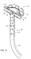
- FIGs. 1 and 2 there is shown an upright conveyor tube 10 having a distribution head 12 mounted to the upper end of same.
- the lower or inlet end 14 of the conveyor tube receives air-entrained granular material such as seed and/or fertiliser by way of a blower and metering devices (both not shown) mounted on an air cart in a manner well known in the art.
- air-entrained material passes upwardly through the conveyor tube 10
- inwardly directed and spaced apart projections 16 disposed in the vertical section of the conveyor tube, and which will be described in full detail hereinafter, serve to impart a controlled degree of turbulence in the upwardly moving flow, which flow then passes into the distribution head 12.
- the distribution head 12 is designed to swing the flow from the vertical direction around into horizontal directions and to divide the flow thus received substantially equally among the several outlet ports 18 which extend radially outwardly from the distribution head in equally angularly spaced relationship to each other. These outlet ports 18 are connected to flexible hoses (not shown) secured to ports 18 by clamps 20, each of which hoses leads to a respective delivery tool.
- Any secondary header may be of similar construction as distribution head 12 and may employ a conveyor tube essentially the same as conveyor tube 10.
- novel head 12 and tube 10 may be employed in the primary and/or any secondary distribution system as required to achieve the desired results.)
- CV coefficient of variation
- the distribution header is symmetrical about its central vertical axis designated X-X.
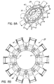
- the distribution head 12 comprises four main parts namely, a top cover 22, a flow deflecting insert 24, a top section 26 and a bottom section 28.
- top and bottom sections 26, 28 as well as the flow deflector 24 are preferably moulded from a polyurethane glass filled plastics material, which material resists wear due to abrasion resulting from the materials being handled and which at the same time provides for economy in the manufacturing processes.
- the distribution head 12 is provided with a centrally located flow inlet spigot 30 which is snugly received in the upper end of the conveyor tube 10 (Figs. 2 and 7).
- Radial flange 31 fixed to the upper end of conveyor tube 10 is provided with spaced apertures through which fasteners 33 extend into head 12 to secure the latter in position on the upper end of tube 10.
- the inlet spigot 30 is integrally formed with the bottom section 28 of the head.
- top and bottom sections 26, 28 of the head together define the above-noted plurality of radially outwardly projecting outlet ports 18 with said outlet ports extending in equally angularly spaced relationship to each other all around the vertical central axis of symmetry X-X of the distribution head 12 and with the outlet end portions of said ports all lying in a common plane normal to said central axis X-X.
- the distribution head 12 includes a flow divider chamber 32 (Fig. 7) defined within the distribution head 12 with the above-noted flow deflector insert 24 being seated within the top section 26 of the head.
- the flow deflector 24 (Figs. 9-12) is provided with a downwardly directed nose 34 accurately centred on the vertical central axis X-X of the distribution head.
- Flow deflector 24 is also provided with a plurality of radially arranged flow confining ridges 36 separated by smoothly contoured valleys 38 each of which is associated with a respective one of the outlet ports 18.
- the flow confining ridges 36 commence immediately downstream of the nose 34, initially being very shallow, with said ridges 36 thence curving gradually around from combined radial and axial directions adjacent the nose 34 into generally radial directions while the contoured valleys 38 between the ridges gradually become deeper such that these valleys in the flow deflector insert 24 ultimately coincide or match up with the interior surfaces of the outlet port portions 18' defined by the top section 26 of the head.
- the bottom section 28 of the head 12 is also provided, immediately downstream of the flow inlet spigot 30, with a plurality of shallow concave transition surfaces 40 each of which leads from the inlet spigot into a respective one of the radially disposed outlet port portions 18' as defined in said bottom section 28. Additionally, the interior surface 42 of the flow inlet spigot 30 gradually tapers inwardly in the direction of the flow to accelerate and centre the flow before it meets the flow deflector insert 24.
- the bottom section 28 is provided with a plurality of conical projections 44 disposed in radially spaced apart relationship and each adapted to enter into a correspondingly shaped recess 46 located in the top section 26 of the header.
- the outer perimeter of the insert is provided with an outwardly projecting annular ledge 48. This ledge 48 is snugly received in a shallow annular step-like recess 50 provided in the top section 26 of the head 12. This ensures that the flow deflector 24 is accurately centred within the top section 26.
- the step-like recess 50 in the top section is provided with angularly spaced apart semi-circular tabs 52 which co-operate with correspondingly sized semi-circular notches 54 provided in the outwardly projecting flange 48 of the flow deflector 24.
- Fasteners (not shown) extending through aligned apertures 51, 53 in the top and bottom sections 26, 28 serve to secure these sections together.
- Flow deflector insert 24 is held in place by the top cover 22 which, in turn, is secured by spaced apart spring clips 55 (Figs. 2 and 7) of suitable design.
- the nose 34 has an elongated cylindrical stem 60 which fits snugly into a central bore 62 defined in the flow divider insert.
- a transverse aperture 64 is provided in the distal end of the stem 60 to receive a pin to retain the nose in the flow deflector 24.
- the nose 34 is provided with an annular shoulder 68 which abuts up against a narrow annular radially directed surface 70 surrounding the central bore 62 of the flow deflector.
- the nose 34 is of a generally truncated conical shape with the extreme proximal end 72 of the nose being flat adjacent its central longitudinal axis with such flat portion thence merging with the conical wall 74 of the nose via an arcuately curved annular transition portion 76.
- the nose 34 should be made of a relatively hard long wearing material thereby to resist abrasion and wear created by the incoming particulate material which of course impinges heavily on the nose 34 during operation. It is of course important that the nose 34 be absolutely symmetrical all about the central axis X-X of the distribution head 12 since any deviation from symmetry will adversely affect the flow division process.
- the lower or inlet end 14 of the conveyor tube receives the air entrained granular material from the aircart and as the air entrained material passes upwardly through the conveyor tube 10, the multiplicity of inwardly directed and spaced apart projections 16 disposed in the vertical section of the conveyor tube impart a controlled degree of turbulence in the upwardly moving flow, which turbulent flow then passes into the distribution head 12 which acts on the flow in the manner described previously.
- the tube 10 includes a straight section 80 of uniform diameter which is vertically positioned when in use and which has a multiplicity of inwardly directed spaced apart projections 16.
- These projections 16 form a plurality of spaced annular rows 82, which rows extend around the lengthways central axis of the tube. The space between at least some of the annular rows 82 decreases in the direction of material travel through the tube 10, i.e. in the direction of flow through the tube from the inlet portion to the outlet portion thereof.
- annular rows 82 of projections 16 which are closest to the distribution head 12 are more closely spaced than rows nearer to the tube inlet.
- the spacings starting at the bottom row could be, for example, 2.25, 2, 1.5, 1.5, 1.5 inches, (5.72, 5.08, 3.81, 3.81, 3.81 cms) i.e. the smallest spacings are near the outlet end.
- the inwardly directed projections 16 are preferably formed by way of " dimples" which are made in the wall of the tube 10 from the exterior, with the relatively thin-wall tube being deformed inwardly to form the corresponding projections 16 .
- the dimples may be made with a round nose punch such that the projections have a semi-spherical or bulbous shape.
- the projections 16 forming the plurality of annular rows 82 are arranged such that projections forming any one row are angularly offset by a selected angle A (Fig. 3) about the lengthways axis of the tube with respect to the projections 16 of an adjacent row. This ensures that all of the material being conveyed is subjected to a measure of turbulence, particularly material which might otherwise tend to travel closely along an interior surface of the tube.
- the lower or inlet end portion 14 of the conveyor tube 10 includes a smoothly curved elbow section 84 leading into the inlet portion of the straight section.
- the curved elbow section may subtend an angle from about 70° to about 90° although with an increasing angle there is a greater tendency for the material to move away from the centre of the tube under the influence of centrifugal force and to follow along the inside wall of the tube 10. Accordingly, this angle should be kept as small as conveniently possible and preferably not greater than about 75°.
- the above-noted straight section 80 has a first space 86 devoid of projections between the elbow section and the first row of projections at the inlet portion and a second space 88 devoid of projections between the last row of projections and the outlet end of the straight section, i.e. the end wherein the inlet spigot of the distribution header is fitted.
- the projections 16 should be concentric within the tube 10.
- the inwardly directed extremities of the projections lie in a base circle having a nominal diameter of about 2 inches (5 cms), this base circle of course being centred with the vertical central axis of the straight portion 80 of the tube.
- This is based on a tube nominal outside diameter of 2.5 inches (6.3 cms), the tube wall being of 16 gauge thickness steel.
- the base circle diameter be 2.00 inches (5.08 cms) + 0, minus 0.030 inches (0.076 cms), giving a tolerance range of 1.97 inches to 2.00 inches (5 to 5.08 cms) for this particular example.
- a range of tube diameters to cover this desired clearance is from about 2.25 to 2.75 inches (5.71 to 6.98 cms). It does not appear that tube diameters outside this range will be accepted by the industry.
- the bottom space is less important but should be less than about 2.5 inches (6.3 cms).
- the columns of projections 16 extend in the lengthways directions of the tubes and the number of columns in the 2.5 inch (6.3 cms) tube was varied between eight and twelve. Twelve columns of projections provided the most acceptable compromise for all products.
- elbow bend angle range has been discussed above and while it can be varied between 70 and 90° , the lower the bend angle the better, with the most acceptable compromise in the CVs being at bend angles not greater than about 75°.
- the fixed criteria of the tube essentially were the elbow angle, offset, dimple tube height and diameter.
- test QA If the results from test QA are compared with those of test RA, it is seen that canola prefers a narrower dimple spacing while wheat prefers a wider spacing. The results also indicate that canola prefers a large top space and wheat prefers a large bottom space.
- canola and high rate fertilisers prefer an aggressive pattern. Wheat seems to prefer a less aggressive pattern. Therefore, it was decided to use only 6 rows at a 3/16" dimple depth. The pattern becomes less aggressive and allows more space to be allocated to the top and bottom spaces. The results of test PG confirm this.
Landscapes
- Life Sciences & Earth Sciences (AREA)
- Soil Sciences (AREA)
- Environmental Sciences (AREA)
- Air Transport Of Granular Materials (AREA)
- Sowing (AREA)
Applications Claiming Priority (3)
| Application Number | Priority Date | Filing Date | Title |
|---|---|---|---|
| GBGB9802527.3A GB9802527D0 (en) | 1998-02-06 | 1998-02-06 | Delivery of seeds by air conveyor |
| GB9802527 | 1998-02-06 | ||
| US09/244,667 US6227770B1 (en) | 1998-02-06 | 1999-02-04 | Conveyor tube and distributor header for air conveyor |
Publications (3)
| Publication Number | Publication Date |
|---|---|
| EP0934689A2 true EP0934689A2 (fr) | 1999-08-11 |
| EP0934689A3 EP0934689A3 (fr) | 2003-03-12 |
| EP0934689B1 EP0934689B1 (fr) | 2005-09-21 |
Family
ID=26313067
Family Applications (1)
| Application Number | Title | Priority Date | Filing Date |
|---|---|---|---|
| EP99300715A Expired - Lifetime EP0934689B1 (fr) | 1998-02-06 | 1999-02-01 | Conduite de distribution et tête de distribution pour convoyeur pneumatique |
Country Status (3)
| Country | Link |
|---|---|
| US (3) | US6227770B1 (fr) |
| EP (1) | EP0934689B1 (fr) |
| GB (1) | GB9802527D0 (fr) |
Cited By (5)
| Publication number | Priority date | Publication date | Assignee | Title |
|---|---|---|---|---|
| US6273648B1 (en) * | 1998-02-06 | 2001-08-14 | Flexi-Coil Ltd. | Distribution header for air conveyor |
| CN101904238A (zh) * | 2010-08-09 | 2010-12-08 | 青岛农业大学 | 播种机的分种头 |
| EP2399443A1 (fr) * | 2010-06-23 | 2011-12-28 | Deere & Company | Ensemble collecteur de distribution pour semoir agricole |
| US8347824B2 (en) | 2010-06-24 | 2013-01-08 | David Christopher Marshall | Combination retractable leash assembly and wearable locket for companion pet |
| EP2893795A1 (fr) * | 2014-01-14 | 2015-07-15 | Livio Sut | Distributeuer pour matériaux granulaires ou microgranulaires sur terre |
Families Citing this family (50)
| Publication number | Priority date | Publication date | Assignee | Title |
|---|---|---|---|---|
| DE19814030C1 (de) * | 1998-03-30 | 1999-03-18 | Kverneland Accord Gmbh & Co Kg | Pneumatisch arbeitende Verteilmaschine mit Flachrohrbogen |
| US6675728B2 (en) | 2002-03-21 | 2004-01-13 | Case, Llc | Vented mini-hopper for bulk feed particle delivery system |
| US6668738B2 (en) | 2002-03-21 | 2003-12-30 | Case, Llc | Bulk fill delivery venturi system |
| US6782835B2 (en) | 2002-03-21 | 2004-08-31 | Case Corporation | Bulk fill delivery recirculation system |
| US6820367B2 (en) | 2002-09-16 | 2004-11-23 | Pacific Regeneration Technologies Inc. | Drill/injector combination for plug fertilization at lift |
| US6834461B2 (en) * | 2002-09-16 | 2004-12-28 | Pacific Regeneration Technologies Inc. | Method to modulate plant growth by injecting a plug at lift |
| US20050072650A1 (en) * | 2003-10-01 | 2005-04-07 | General Electric Company | Method for transporting plastic pellets |
| FR2870836B1 (fr) * | 2004-05-27 | 2007-08-10 | F2 C2 System Sa | Dispositif autorisant le deplacement de pieces a l'interieur d'une conduite |
| US7264423B2 (en) * | 2005-02-02 | 2007-09-04 | Cnh Canada, Ltd. | Hose restraint apparatus |
| US7213617B2 (en) * | 2005-07-12 | 2007-05-08 | Deere & Company | Airflow divider with shutoff |
| US20070166114A1 (en) * | 2005-12-23 | 2007-07-19 | Whitten James R | Orienting means for condom transport equipment |
| SE530058C2 (sv) * | 2005-12-23 | 2008-02-19 | Dustcontrol Internat Ab | Rörledningssystem |
| US7875192B2 (en) * | 2006-12-20 | 2011-01-25 | Carter Day International, Inc. | Slurry flow divider |
| AU2010200082B2 (en) * | 2009-01-09 | 2016-08-04 | James Dunstan | Air seeder venting system |
| PL216367B1 (pl) * | 2009-05-14 | 2014-03-31 | Int Tobacco Machinery Poland | Sposób i urządzenie do dystrybucji krajanki tytoniowej do zasilania maszyn produkujących papierosy |
| US8469636B2 (en) * | 2010-06-16 | 2013-06-25 | Deere & Company | Commodity splitter for an air delivery system |
| US8544498B2 (en) | 2010-06-23 | 2013-10-01 | Deere & Company | Manifold and distribution manifold assembly for air-entrained material |
| US8821078B2 (en) | 2011-01-07 | 2014-09-02 | Conagra Foods Lamb Weston, Inc. | Fluid-based article distribution and sorting system |
| US8684636B2 (en) * | 2011-03-09 | 2014-04-01 | James Dunstan | Air seeder venting system |
| US8403602B2 (en) * | 2011-03-16 | 2013-03-26 | Babcock Power Services, Inc. | Coal flow splitters and distributor devices |
| EP2717668B1 (fr) * | 2011-06-10 | 2016-04-27 | Great Plains Manufacturing, Incorporated | Tour de distribution de graines pour un semoir pneumatique |
| US8656848B2 (en) | 2011-06-10 | 2014-02-25 | Great Plains Manufacturing, Inc. | Seed distribution tower for an air seeder |
| CA2756635A1 (fr) * | 2011-11-01 | 2013-05-01 | Straw Track Manufacturing Inc. | Appareil collecteur de semoir pneumatique |
| BR212014016514Y1 (pt) | 2012-01-09 | 2019-04-24 | Cnh Industrial Canada, Ltd. | Montagem giratória divisora de fluxo para sistemas de distribuição de produtos agrícolas |
| US9265190B2 (en) * | 2013-01-09 | 2016-02-23 | Cnh Industrial America Llc | Seed inductor box for an agricultural implement having multiple air paths |
| US9072216B2 (en) | 2013-01-09 | 2015-07-07 | Cnh Industrial America Llc | Conduit system for a pneumatic distribution system of an agricultural implement |
| US9204592B2 (en) | 2013-01-09 | 2015-12-08 | Cnh Industrial America Llc | System for securing inductor segments to an inductor assembly of an agricultural implement |
| US9215840B2 (en) * | 2013-01-09 | 2015-12-22 | Cnh Industrial Canada, Ltd. | Seed inductor for an agricultural implement having an air bypass channel |
| US9439344B2 (en) * | 2013-01-09 | 2016-09-13 | Cnh Industrial Canada, Ltd. | Mirrored inductor segment pairs of an inductor box of an agricultural implement |
| US9215841B2 (en) * | 2013-01-09 | 2015-12-22 | Cnh Industrial America Llc | Seed inductor for an agricultural implement having an adjustable air bypass |
| US9192093B2 (en) | 2013-01-09 | 2015-11-24 | Cnh Industrial Canada, Ltd. | Seed inductor box for an agricultural implement having a fluidization chamber |
| US9316445B2 (en) | 2013-03-14 | 2016-04-19 | Crom, Llc | Spider diffuser system |
| RU2557106C2 (ru) * | 2013-12-04 | 2015-07-20 | Федеральное государственное бюджетное образовательное учреждение высшего профессионального образования "Государственный аграрный университет Северного Зауралья" | Делительная головка пневматической сеялки с изменяемым диаметром выходного отверстия |
| US9480203B2 (en) * | 2014-06-18 | 2016-11-01 | Crary Industries, Inc. | Harvester feed housing cleaning with pressurized fluid |
| US9585304B2 (en) | 2014-10-17 | 2017-03-07 | Cnh Industrial America Llc | 3-way seed flow splitter for planters |
| US9826676B2 (en) * | 2015-09-30 | 2017-11-28 | Deere & Company | Seed dispersion unit |
| CA2911182C (fr) * | 2015-11-03 | 2019-01-15 | Norbert Beaujot | Collecteur de semoir pneumatique a uniformite de distribution amelioree |
| US10344778B2 (en) * | 2016-02-29 | 2019-07-09 | Haier Us Appliance Solutions, Inc. | Ejector for a sealed system |
| RU2634485C2 (ru) * | 2016-04-19 | 2017-10-31 | Федеральное государственное бюджетное образовательное учреждение высшего образования "Государственный аграрный университет Северного Зауралья" (ФГБОУ ВО ГАУ Северного Зауралья) | Делительная головка пневматической сеялки |
| RU2636204C2 (ru) * | 2016-04-25 | 2017-11-21 | Федеральное государственное бюджетное образовательное учреждение высшего образования "Государственный аграрный университет Северного Зауралья" (ФГБОУ ВО ГАУ Северного Зауралья) | Делительная головка пневматической сеялки с механизмом очистки семяпровода |
| US10117376B2 (en) * | 2016-08-31 | 2018-11-06 | Cnh Industrial Canada, Ltd. | Equalizing air pressure on air seeders |
| US10143129B2 (en) | 2017-02-27 | 2018-12-04 | Cnh Industrial Canada, Ltd. | Flow splitter for distributing agricultural products and related system |
| SE540982C2 (sv) * | 2017-06-20 | 2019-02-12 | Vaederstad Holding Ab | Fördelarenhet för fördelning av materialblandat luftflöde hos ett lantbruksredskap, lantbruksredskap omfattande sådan fördelarenhet samt förfarande för fördelning av materialblandat luftflöde |
| US10427113B2 (en) * | 2017-07-18 | 2019-10-01 | Cnh Industrial Canada, Ltd. | Horizontal product distribution system using static baffles in a distributor |
| WO2019210380A1 (fr) * | 2018-04-30 | 2019-11-07 | Stara S/a. Industria De Implementos Agrícolas | Agencement appliqué à un système de distribution pneumatique sur des barres de pulvérisation de pulvérisateurs |
| US10709055B2 (en) | 2018-05-24 | 2020-07-14 | Cnh Industrial Canada, Ltd. | Drop chute deflector for enhancing entrainment of granular product in an airstream of an agricultural product applicator |
| USD904460S1 (en) * | 2018-06-19 | 2020-12-08 | Curtis O'Hare | Air manifold |
| AU2019318553B2 (en) * | 2018-08-10 | 2022-08-04 | Great Plains Manufacturing, Inc. | Seed-flow adjustment system |
| US10743462B2 (en) * | 2019-01-11 | 2020-08-18 | Cnh Industrial America Llc | Flow splitter for distributing agricultural products and related system |
| DE102022118253A1 (de) | 2022-07-21 | 2024-02-01 | Amazonen-Werke H. Dreyer SE & Co. KG | Strömungseinrichtung zur zumindest teilweisen Führung einer Fördergutströmung, Verteilerkopfs für eine landwirtschaftliche Ausbringmaschine und landwirtschaftlichen Ausbringmaschine |
Citations (9)
| Publication number | Priority date | Publication date | Assignee | Title |
|---|---|---|---|---|
| US3189230A (en) | 1962-03-20 | 1965-06-15 | Robert V Gillespie | Seeding device |
| US4191500A (en) | 1977-07-27 | 1980-03-04 | Rockwell International Corporation | Dense-phase feeder method |
| CA1097149A (fr) | 1979-02-15 | 1981-03-10 | Daniel W. Kelm | Traduction non-disponible |
| US4413935A (en) | 1981-06-29 | 1983-11-08 | Combustion Engineering, Inc. | Flow splitter for dividing a stream of pulverulent material into multiple streams |
| CA1167704A (fr) | 1981-07-22 | 1984-05-22 | Prasco Super Seeder Ltd. | Tube distributeur pour applicateur pneumatique |
| EP0211295A1 (fr) | 1985-08-05 | 1987-02-25 | Paul Wurth S.A. | Procédé et dispositif d'injection, par voie pneumatique, de quantités dosées de matières pulvérulentes dans une enceinte se trouvant sous pression variable |
| US4717289A (en) | 1987-01-16 | 1988-01-05 | Morris Rod Weeder Company, Ltd. | Horizontally disposed apparatus for the random distribution of seeds and granular materials |
| SU1496668A1 (ru) | 1987-12-07 | 1989-07-30 | Научно-Производственное Объединение По Сельскохозяйственному Машиностроению "Висхом" | Распределительна головка зерновой пневматической се лки |
| CA2111611A1 (fr) | 1993-12-16 | 1995-06-17 | Gerard F.J. Bourgault | Systeme de distribution centrale des semences |
Family Cites Families (24)
| Publication number | Priority date | Publication date | Assignee | Title |
|---|---|---|---|---|
| CA867226A (en) | 1971-03-30 | Weiste Heinrich | Method and apparatus for spreading granular material | |
| US1871853A (en) * | 1927-08-09 | 1932-08-16 | Joseph E Kennedy | Pneumatic transporting and distributing of pulverized material |
| US1850937A (en) * | 1927-11-28 | 1932-03-22 | George S Messinger | Distributor |
| US2171205A (en) | 1937-08-26 | 1939-08-29 | Louis A Zinke | Powder distributing attachment for tractors |
| DE1657591B1 (de) | 1966-01-22 | 1970-07-16 | Heinrich Weiste | Vorrichtung zum Saeen von Korn und/oder Streuen von koernigem Duenger |
| SU571212A1 (ru) | 1975-12-09 | 1977-09-05 | Белорусская Ордена Трудового Красного Знамени Сельскохозяйственная Академия | Распределительное устройство дл супычих материалов |
| US4024822A (en) | 1975-12-22 | 1977-05-24 | Arthur Ross | Pneumatic seeder assembly |
| CA1040483A (fr) | 1977-01-05 | 1978-10-17 | Pride Industries Ltd. | Tete pneumatique pour semoir |
| US4280419A (en) | 1977-03-21 | 1981-07-28 | International Harvester Company | Pneumatic system for conveying granular material |
| CA1060720A (fr) | 1977-09-22 | 1979-08-21 | Jerome Bechard | Systeme pneumatique d'ensemencement |
| SU757433A1 (ru) | 1977-12-20 | 1980-08-23 | Univ Dnepropetrowsk | Делитель потока аэросмеси 1 |
| SU694116A1 (ru) | 1978-04-25 | 1979-10-30 | Украинский Научно-Исследовательский Институт Защиты Почв От Эррозии Всесоюзной Ордена Ленина Академии Сельскохозяйственных Наук Им. В.И. Ленина | Пневматическа се лка |
| SU757443A1 (ru) | 1978-07-11 | 1980-08-23 | Vnii Rezinotekh Mash | Устройство для укладки заготовок протекторов на откидные полки передвижных стеллажей 1 |
| SU801771A1 (ru) | 1979-05-24 | 1981-02-07 | Украинский Научно-Исследовательс-Кий Институт Механизации И Элект-Рификации Сельского Хозяйства | Пневматическа распределительна гОлОВКА |
| CA1154323A (fr) | 1980-03-03 | 1983-09-27 | Austin T. Ryan | Injection de granules dans un debit gazeux |
| SE430370B (sv) * | 1982-07-27 | 1983-11-14 | Ingf Alf Andersson Hb | Sett och anordning for spridning och fordelning av ett partikelformigt fast eller flytande material |
| US4562968A (en) | 1984-03-19 | 1986-01-07 | Dry Sprayer, Inc. | Pneumatic spreader |
| DE3615075C1 (de) * | 1986-05-03 | 1986-11-13 | Rauch Landmaschinenfabrik GmbH, 7573 Sinzheim | Vorrichtung zum pneumatischen Streuen von Duenger oder dergl. |
| DE3701290A1 (de) * | 1987-01-17 | 1988-07-28 | Rauch Landmaschfab Gmbh | Vorrichtung zum pneumatischen streuen von duenger |
| CA2073237A1 (fr) | 1991-07-05 | 1993-01-06 | Russell James Memory | Chargeur diviseur multivoies pour semoirs pneumatiques |
| DE19522060A1 (de) * | 1995-06-17 | 1996-12-19 | Amazonen Werke Dreyer H | Verteilerkopf für eine pneumatische Sämaschine |
| DE19748821A1 (de) * | 1997-11-05 | 1999-05-06 | Itw Gema Ag | Pulver-Sprühbeschichtungsvorrichtung |
| GB9802527D0 (en) * | 1998-02-06 | 1998-04-01 | Flexi Coil Ltd | Delivery of seeds by air conveyor |
| DE19820914B4 (de) * | 1998-05-09 | 2010-01-07 | TRüTZSCHLER GMBH & CO. KG | Vorrichtung zum Leiten von in Luft schwebend geförderten textilen Faserflocken, z. B. Baumwolle, Chemiefasern, bei Spinnereivorbereitungsmaschinen |
-
1998
- 1998-02-06 GB GBGB9802527.3A patent/GB9802527D0/en not_active Ceased
-
1999
- 1999-02-01 EP EP99300715A patent/EP0934689B1/fr not_active Expired - Lifetime
- 1999-02-04 US US09/244,667 patent/US6227770B1/en not_active Expired - Lifetime
-
2000
- 2000-12-29 US US09/750,120 patent/US6290433B2/en not_active Expired - Lifetime
- 2000-12-29 US US09/750,349 patent/US6273648B1/en not_active Expired - Lifetime
Patent Citations (9)
| Publication number | Priority date | Publication date | Assignee | Title |
|---|---|---|---|---|
| US3189230A (en) | 1962-03-20 | 1965-06-15 | Robert V Gillespie | Seeding device |
| US4191500A (en) | 1977-07-27 | 1980-03-04 | Rockwell International Corporation | Dense-phase feeder method |
| CA1097149A (fr) | 1979-02-15 | 1981-03-10 | Daniel W. Kelm | Traduction non-disponible |
| US4413935A (en) | 1981-06-29 | 1983-11-08 | Combustion Engineering, Inc. | Flow splitter for dividing a stream of pulverulent material into multiple streams |
| CA1167704A (fr) | 1981-07-22 | 1984-05-22 | Prasco Super Seeder Ltd. | Tube distributeur pour applicateur pneumatique |
| EP0211295A1 (fr) | 1985-08-05 | 1987-02-25 | Paul Wurth S.A. | Procédé et dispositif d'injection, par voie pneumatique, de quantités dosées de matières pulvérulentes dans une enceinte se trouvant sous pression variable |
| US4717289A (en) | 1987-01-16 | 1988-01-05 | Morris Rod Weeder Company, Ltd. | Horizontally disposed apparatus for the random distribution of seeds and granular materials |
| SU1496668A1 (ru) | 1987-12-07 | 1989-07-30 | Научно-Производственное Объединение По Сельскохозяйственному Машиностроению "Висхом" | Распределительна головка зерновой пневматической се лки |
| CA2111611A1 (fr) | 1993-12-16 | 1995-06-17 | Gerard F.J. Bourgault | Systeme de distribution centrale des semences |
Cited By (8)
| Publication number | Priority date | Publication date | Assignee | Title |
|---|---|---|---|---|
| US6273648B1 (en) * | 1998-02-06 | 2001-08-14 | Flexi-Coil Ltd. | Distribution header for air conveyor |
| US6290433B2 (en) * | 1998-02-06 | 2001-09-18 | Flexi-Coil Ltd. | Distribution system for conveying air-entrained material |
| EP2399443A1 (fr) * | 2010-06-23 | 2011-12-28 | Deere & Company | Ensemble collecteur de distribution pour semoir agricole |
| US8505574B2 (en) | 2010-06-23 | 2013-08-13 | Deere & Company | Lid for a manifold |
| US8347824B2 (en) | 2010-06-24 | 2013-01-08 | David Christopher Marshall | Combination retractable leash assembly and wearable locket for companion pet |
| CN101904238A (zh) * | 2010-08-09 | 2010-12-08 | 青岛农业大学 | 播种机的分种头 |
| CN101904238B (zh) * | 2010-08-09 | 2012-05-30 | 青岛农业大学 | 播种机的分种头 |
| EP2893795A1 (fr) * | 2014-01-14 | 2015-07-15 | Livio Sut | Distributeuer pour matériaux granulaires ou microgranulaires sur terre |
Also Published As
| Publication number | Publication date |
|---|---|
| EP0934689B1 (fr) | 2005-09-21 |
| US20010016151A1 (en) | 2001-08-23 |
| EP0934689A3 (fr) | 2003-03-12 |
| US6273648B1 (en) | 2001-08-14 |
| US6290433B2 (en) | 2001-09-18 |
| US20010014258A1 (en) | 2001-08-16 |
| US6227770B1 (en) | 2001-05-08 |
| GB9802527D0 (en) | 1998-04-01 |
Similar Documents
| Publication | Publication Date | Title |
|---|---|---|
| US6227770B1 (en) | Conveyor tube and distributor header for air conveyor | |
| US4575284A (en) | Distribution tube for pneumatic applicator | |
| EP3150042B1 (fr) | Semoir avec une unité d'épandage de semences | |
| EP3646691B1 (fr) | Dispositif de positionnement de graines, système de distribution de graines le comprenant, machine d'ensemencement et procédé de positionnement de graines | |
| CA2911580C (fr) | Commande d'ecoulement d'air destinee aux produits agricoles | |
| US4717289A (en) | Horizontally disposed apparatus for the random distribution of seeds and granular materials | |
| US10827668B2 (en) | Air distribution system for a pneumatic conveying system | |
| US5655468A (en) | Delivery system for an agricultural implement | |
| US20150098767A1 (en) | Air seeder manifold apparatus | |
| US6116284A (en) | Guide structure for pneumatic applicator | |
| CA2260439C (fr) | Tube transporteur ameliore et collecteur de distribution pour transporteur pneumatique | |
| CA2559626C (fr) | Tube transporteur ameliore et collecteur de distribution pour transporteur pneumatique | |
| AU2003204019B2 (en) | Improved distribution head for an agricultural pneumatic conveyance device | |
| CA1097149A (fr) | Traduction non-disponible | |
| US4264242A (en) | Method and apparatus for distributing pulverulent or particulate materials to a plurality of dispensing points, e.g. for sowing seeds or spreading fertilizer | |
| WO2005004579A1 (fr) | Dispositif de tete d'appareil de distribution | |
| CN114223357B (zh) | 类球形种子约束导送式导种装置及其精量穴播器 | |
| CA2073237A1 (fr) | Chargeur diviseur multivoies pour semoirs pneumatiques | |
| EP3641523A1 (fr) | Distributeur pour distribuer un flux d'air mélangé à des materiaux dans un outil agricole, outil agricole comprenant un tel distributeur et procédé de distribution d'un flux d'air mélangé à des materiaux |
Legal Events
| Date | Code | Title | Description |
|---|---|---|---|
| PUAI | Public reference made under article 153(3) epc to a published international application that has entered the european phase |
Free format text: ORIGINAL CODE: 0009012 |
|
| AK | Designated contracting states |
Kind code of ref document: A2 Designated state(s): AT BE CH CY DE DK ES FI FR GB GR IE IT LI LU MC NL PT SE |
|
| AX | Request for extension of the european patent |
Free format text: AL;LT;LV;MK;RO;SI |
|
| PUAL | Search report despatched |
Free format text: ORIGINAL CODE: 0009013 |
|
| AK | Designated contracting states |
Kind code of ref document: A3 Designated state(s): AT BE CH CY DE DK ES FI FR GB GR IE IT LI LU MC NL PT SE Designated state(s): AT BE CH CY DE DK ES FI FR GB GR IE IT LI LU MC NL PT SE |
|
| AX | Request for extension of the european patent |
Extension state: AL LT LV MK RO SI |
|
| 17P | Request for examination filed |
Effective date: 20030828 |
|
| AKX | Designation fees paid |
Designated state(s): DE FR GB |
|
| 17Q | First examination report despatched |
Effective date: 20031124 |
|
| RAP1 | Party data changed (applicant data changed or rights of an application transferred) |
Owner name: CNH CANADA LTD. |
|
| GRAP | Despatch of communication of intention to grant a patent |
Free format text: ORIGINAL CODE: EPIDOSNIGR1 |
|
| GRAS | Grant fee paid |
Free format text: ORIGINAL CODE: EPIDOSNIGR3 |
|
| GRAA | (expected) grant |
Free format text: ORIGINAL CODE: 0009210 |
|
| AK | Designated contracting states |
Kind code of ref document: B1 Designated state(s): DE FR GB |
|
| REG | Reference to a national code |
Ref country code: GB Ref legal event code: FG4D |
|
| REF | Corresponds to: |
Ref document number: 69927309 Country of ref document: DE Date of ref document: 20051027 Kind code of ref document: P |
|
| REF | Corresponds to: |
Ref document number: 69927309 Country of ref document: DE Date of ref document: 20060202 Kind code of ref document: P |
|
| ET | Fr: translation filed | ||
| PLBE | No opposition filed within time limit |
Free format text: ORIGINAL CODE: 0009261 |
|
| STAA | Information on the status of an ep patent application or granted ep patent |
Free format text: STATUS: NO OPPOSITION FILED WITHIN TIME LIMIT |
|
| 26N | No opposition filed |
Effective date: 20060622 |
|
| PGFP | Annual fee paid to national office [announced via postgrant information from national office to epo] |
Ref country code: DE Payment date: 20140118 Year of fee payment: 16 |
|
| REG | Reference to a national code |
Ref country code: DE Ref legal event code: R082 Ref document number: 69927309 Country of ref document: DE Representative=s name: G. KOCH UND KOLLEGEN, DE Effective date: 20140417 Ref country code: DE Ref legal event code: R081 Ref document number: 69927309 Country of ref document: DE Owner name: CNH INDUSTRIAL CANADA LTD., CA Free format text: FORMER OWNER: CNH CANADA LTD., TORONTO, ONTARIO, CA Effective date: 20140417 Ref country code: DE Ref legal event code: R081 Ref document number: 69927309 Country of ref document: DE Owner name: CNH INDUSTRIAL CANADA LTD., CA Free format text: FORMER OWNER: CNH CANADA LTD., TORONTO, CA Effective date: 20140417 |
|
| REG | Reference to a national code |
Ref country code: GB Ref legal event code: 746 Effective date: 20150123 |
|
| REG | Reference to a national code |
Ref country code: DE Ref legal event code: R119 Ref document number: 69927309 Country of ref document: DE |
|
| REG | Reference to a national code |
Ref country code: FR Ref legal event code: PLFP Year of fee payment: 18 |
|
| PG25 | Lapsed in a contracting state [announced via postgrant information from national office to epo] |
Ref country code: DE Free format text: LAPSE BECAUSE OF NON-PAYMENT OF DUE FEES Effective date: 20150901 |
|
| PGFP | Annual fee paid to national office [announced via postgrant information from national office to epo] |
Ref country code: FR Payment date: 20160112 Year of fee payment: 18 Ref country code: GB Payment date: 20160114 Year of fee payment: 18 |
|
| GBPC | Gb: european patent ceased through non-payment of renewal fee |
Effective date: 20170201 |
|
| REG | Reference to a national code |
Ref country code: FR Ref legal event code: ST Effective date: 20171031 |
|
| PG25 | Lapsed in a contracting state [announced via postgrant information from national office to epo] |
Ref country code: FR Free format text: LAPSE BECAUSE OF NON-PAYMENT OF DUE FEES Effective date: 20170228 |
|
| PG25 | Lapsed in a contracting state [announced via postgrant information from national office to epo] |
Ref country code: GB Free format text: LAPSE BECAUSE OF NON-PAYMENT OF DUE FEES Effective date: 20170201 |