EP0933168A2 - Clamping device - Google Patents
Clamping device Download PDFInfo
- Publication number
- EP0933168A2 EP0933168A2 EP99101165A EP99101165A EP0933168A2 EP 0933168 A2 EP0933168 A2 EP 0933168A2 EP 99101165 A EP99101165 A EP 99101165A EP 99101165 A EP99101165 A EP 99101165A EP 0933168 A2 EP0933168 A2 EP 0933168A2
- Authority
- EP
- European Patent Office
- Prior art keywords
- clamping device
- elements
- shell
- end position
- head
- Prior art date
- Legal status (The legal status is an assumption and is not a legal conclusion. Google has not performed a legal analysis and makes no representation as to the accuracy of the status listed.)
- Withdrawn
Links
Images

Classifications
-
- B—PERFORMING OPERATIONS; TRANSPORTING
- B25—HAND TOOLS; PORTABLE POWER-DRIVEN TOOLS; MANIPULATORS
- B25B—TOOLS OR BENCH DEVICES NOT OTHERWISE PROVIDED FOR, FOR FASTENING, CONNECTING, DISENGAGING OR HOLDING
- B25B5/00—Clamps
- B25B5/06—Arrangements for positively actuating jaws
- B25B5/12—Arrangements for positively actuating jaws using toggle links
- B25B5/122—Arrangements for positively actuating jaws using toggle links with fluid drive
-
- B—PERFORMING OPERATIONS; TRANSPORTING
- B25—HAND TOOLS; PORTABLE POWER-DRIVEN TOOLS; MANIPULATORS
- B25B—TOOLS OR BENCH DEVICES NOT OTHERWISE PROVIDED FOR, FOR FASTENING, CONNECTING, DISENGAGING OR HOLDING
- B25B5/00—Clamps
- B25B5/16—Details, e.g. jaws, jaw attachments
Definitions
- the invention relates to a clamping device for clamping Workpieces according to the preamble of the independent claim 1.
- Such clamping devices are, for example, according to DE-U-92 15 151.5 known.
- the invention is accordingly based on the object of a tensioning device of the type mentioned above with regard to their end position interrogation device to train and improve in such a way that they can easily and without auxiliary tools to changed installation conditions, Adjustment paths or operating conditions of the Clamping device is adaptable.
- This task is on and with a clamping device of the generic type Type solved according to the invention in that the end position interrogation device from one of the end position query elements laterally receiving half-shell and this from at least a head part and a connecting part is formed, head part and connecting part to each other by means of releasable connecting elements can be aligned aligned and with connecting and fixing elements are provided for the head piece of the clamping device.
- Advantageous further developments and embodiments result according to the subclaims.
- This training according to the invention is a kind of variable-length carrier for the actual end position query elements created together with these query elements (e.g. microswitches, sensors or the like.) a total in insert the clamping device head piece and position it precisely easily lockable cassette.
- An embodiment is preferred in which between head and Connection part at least one with corresponding connecting elements provided intermediate part can be used because this Embodiment the greater adaptability to different lengths Offers recesses of clamping devices and the head and Connection parts can always be maintained without change.
- the manufacturer can restrict himself to one of the two parts with different lengths to produce and keep ready.
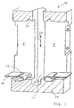
- Fig. 1 the interior view is in principle in a half section a part of a clamping device head piece 10 is shown, with a range of motion in the jig head 10 for a linear actuator that can be actuated by a drive A.
- LS is designated 27.
- Such a linear actuator LS moves itself in the direction of arrow 28.
- a sensor G arranged laterally out of the movement space 27 stands out and explained in more detail below End position query element 2 (here microswitch) actuated.
- End of the linear actuator LS is (not particularly shown) with coupled to the swivel arm SA in bearing L, the via actuator LS between two end positions (see Fig. 7) is adjustable, which must be queried.
- an end position interrogation device consists, as shown, for example, of a half-shell 1, which is open to the movement space 27 of the linear actuator LS and to a flat side.
- an end position sensing device 2 In the interior of the half-shell 1, two end position sensing elements 2 are arranged, which are electrically connected by means of cables 5 to a plug contact 6, which makes the signals of the end position sensing elements 2 accessible.
- This plug contact 6 is arranged at a rear opening 7 of the half-shell 1.
- the cables 5 are laid freely in a channel-like area 4, are flexible and thus allow the position of the end position interrogation element 2 to be changed along the direction of movement 28 of the linear actuator LS.
- the end position query element 2 are held within the half-shell 1 by means of pins, not shown here, arranged on the shell side, which are inserted into the bores 3 of a row of holes in the desired position.
- each of the two end position sensing elements 2 is laterally fixed by inserting the entire end position sensing device into the recess 9 or 9 'of the clamping device head piece 10, as the edge 8 of the half-shell 1 advantageously lies at the same height as the surface of the end position sensing elements 2 (see Fig. 8). Falling out of the end position interrogation elements 2 from the half-shell 1 is thus reliably prevented by their walls after their insertion into one of the recesses 9, 9 '.
- the head part 11 and connecting part 13 by means of releasable connecting elements 14, 19; 15, 16 can be connected to one another and with connecting and fixing elements 17,21 to the head piece 10 are provided.
- the half-shell 1 is constructed modularly from the head part 11, intermediate part / s 12 and connecting part 13.
- the half-shell 1 is segmented in such a way that the same or different lengths of individual parts 11, 12, 13 result which, when put together, result in a half-shell 1 which can be adapted to the required overall lengths and setting ranges of the end position query elements 2.
- only a head part 11 and a connection part 13 are joined, these two parts each having the bores 3 for inserting the end position interrogation switch 2.
- either the head part 11 and the connecting part 13 can be extended, or one or more intermediate parts 12 are inserted between the head part 11 and the connecting part 13, which together with the head part 11 and the connecting part 13 then, according to the required distance, the adjustment path via arrangement of Define end position query elements 2.
- the head part 11 and the connecting part 13 can always be of the same length and for each application with one or more intermediate parts 12 from a series, differently long intermediate parts 12 can also be fitted together.
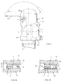
- connection between head part 11, connecting part 13 or intermediate part 12, as shown in FIGS. 4a and 4b by means of pins 14 which are in corresponding bores (not shown) of the adjacent part can be inserted.
- FIG. 4c or 4b can be a latchable Connection by means of a locking hook 15 and a locking recess 16 can be provided at the neighboring part.
- a precise adjustment of the end position interrogation device for Linear actuator and its encoder G can be advantageously simple Realize that on the outside and on top of the half shell 1 a rounded cam as a connection and fixing element 17th is arranged, the in the intended plug-in state End position interrogation device in the recess 9 or 9 'in a corresponding recess 18 engages the head 10. This is the exact insertion position of the end position interrogation device always guaranteed safely and without complex adjustment. It goes without saying that in kinematic reversal also a cam 19 in the wall of the recess 9 or 9 ' a corresponding recess of the half-shell 1 can lock.
- a leaf spring 22 between half shell 1 and wall of recess 9, 9 ' are arranged so that they are fixed in the recess 9, 9' is and with an associated cam as a fixing element 21 on the connecting part 13 of the half-shell 1 in the inserted state locked.
- such a spring element also be integrally formed on the connecting part 13, wherein the resilient locking part 23 on an edge 24 of the recess 9, 9 ' locked.
- a stop edge 25 is provided the flank of a common locking groove opposite the edge 24 25 'forms.
- FIGS. 8A, B which represents a section along line II in FIG. 7, in which the arrangement of the end position interrogation device is only indicated by dashed lines.
- 8A makes it clear that the actual query elements 2, which are attached to the half-shell 1 consisting of the described individual parts as carriers, are held in their inserted position by the adjacent flank of the head piece 10.
- FIG. 8B it is advantageously provided, according to FIG. 8B, to assign the half-shell 1 a correspondingly dimensioned spacing plate 1 'on its flank, which in a suitable manner on the one or the other side of the half-shell is connected to it.
Landscapes
- Engineering & Computer Science (AREA)
- Mechanical Engineering (AREA)
- Clamps And Clips (AREA)
- Transmission And Conversion Of Sensor Element Output (AREA)
- Jigs For Machine Tools (AREA)
Abstract
Description
Die Erfindung betrifft eine Spannvorrichtung zum Festspannen von
Werkstücken gemäß Oberbegriff des unabhängigen Patentanspruches
1.The invention relates to a clamping device for clamping
Workpieces according to the preamble of the
Derartige Spannvorrichtungen sind bspw. nach der DE-U-92 15 151.5 bekannt. Für den Betrieb solcher Spannvorrichtungen z.B. in automatischen Fertigungseinrichtungen aber auch in Einzelverwendung ist es von Interesse, zumindest die Endstellungen der Spannarme solcher Spannvorrichtungen zu überwachen und beispielsweise als Steuersignal anzuzeigen und/oder für die Steuerung der Spannvorrichtung selbst oder auch von beteiligten Bearbeitungsmaschinen auszunutzen.Such clamping devices are, for example, according to DE-U-92 15 151.5 known. For the operation of such clamping devices e.g. in automatic production facilities but also in single use it is of interest, at least the end positions of the To monitor clamping arms of such clamping devices and for example display as a control signal and / or for control the clamping device itself or from processing machines involved to take advantage of.
Abgesehen von der Spannvorrichtung gemäß der vorerwähnten DE-U-92 15 151.5, bei der die Endstellungsabfrageelemente selbst unmittelbar, d.h., ohne besonderen Träger im Kopfstück der Spannvorrichtung angeordnet sind, ist es auch bekannt, derartige Endstellungsabfrageeinrichtungen als in das Kopfstück einsetzbare Kassetten auszubilden. Hierzu wird bspw. auf die EP-A-0855 800 A1 verwiesen. Soweit bekannt, sind derartige Kassetten immer nur auf einen speziellen Spannvorrichtungstyp und insbesondere die Abmessungen von deren Aufnahmeausnehmung abgestellt und werden mit Schrauben fixiert, was zur Montage und Demontage der Kassetten Hilfswerkzeuge erfordert.Apart from the tensioning device according to the aforementioned DE-U-92 15 151.5, in which the end position query elements themselves, i.e. without a special support in the head piece of the clamping device are arranged, it is also known, such end position interrogation devices than usable in the head piece Train cassettes. For this purpose, for example, EP-A-0855 800 A1 referenced. As far as is known, such cartridges are always only to a special type of clamping device and in particular the Dimensions of their receiving recess are and are fixed with screws, what to assemble and disassemble the cassettes Auxiliary tools required.
Der Erfindung liegt demgemäß die Aufgabe zugrunde, eine Spannvorrichtung der eingangs genannten Art hinsichtlich ihrer Endstellungsabfrageeinrichtung derart auszubilden und zu verbessern, daß sie einfach und ohne Hilfswerkzeuge an geänderte Einbauverhältnisse, Verstellwege oder Betriebsbedingungen der Spannvorrichtung anpaßbar ist. The invention is accordingly based on the object of a tensioning device of the type mentioned above with regard to their end position interrogation device to train and improve in such a way that they can easily and without auxiliary tools to changed installation conditions, Adjustment paths or operating conditions of the Clamping device is adaptable.
Diese Aufgabe ist an und mit einer Spannvorrichtung der gattungsgemäßen Art nach der Erfindung dadurch gelöst, daß die Endstellungsabfrageeinrichtung aus einer die Endstellungsabfrageelemente seitlich aufnehmenden Halbschale und diese aus zumindest einem Kopfteil und einem Anschlußteil gebildet ist, wobei Kopfteil und Anschlußteil mittels lösbarer Verbindungselemente zueinander fluchtend verbindbar und mit Anschluß-und Fixierungselementen zum Kopfstück der Spannvorrichtung versehen sind. Vorteilhafte Weiterbildungen und Ausführungsformen ergeben sich nach den Unteransprüchen. Durch diese erfindungsgemäße Ausbildung ist gewissermaßen ein längenveränderlicher Träger für die eigentlichen Endstellungsabfrageelemente geschaffen, der zusammen mit diesen Abfrageelementen (bspw. Mikroschalter, Sensoren od.dgl.) eine insgesamt in das Spannvorrichtungskopfstück einsetz- und darin positionsgenau einfach verrastbare Kassette bildet.This task is on and with a clamping device of the generic type Type solved according to the invention in that the end position interrogation device from one of the end position query elements laterally receiving half-shell and this from at least a head part and a connecting part is formed, head part and connecting part to each other by means of releasable connecting elements can be aligned aligned and with connecting and fixing elements are provided for the head piece of the clamping device. Advantageous further developments and embodiments result according to the subclaims. This training according to the invention is a kind of variable-length carrier for the actual end position query elements created together with these query elements (e.g. microswitches, sensors or the like.) a total in insert the clamping device head piece and position it precisely easily lockable cassette.
Bevorzugt wird eine Ausführungsform, bei der zwischen Kopf- und Anschlußteil mindestens ein mit entsprechend passenden Verbindungselementen versehenes Zwischenteil einsetzbar ist, da diese Ausführungsform die größere Anpaßbarkeit an längenunterschiedliche Ausnehmungen von Spannvorrichtungen bietet und die Kopf- und Anschlußteile immer ohne Veränderung beibehalten werden können.An embodiment is preferred in which between head and Connection part at least one with corresponding connecting elements provided intermediate part can be used because this Embodiment the greater adaptability to different lengths Offers recesses of clamping devices and the head and Connection parts can always be maintained without change.
Sofern die einfachste, d.h., die nur zweiteilige Ausführungsform vorgesehen ist, kann sich auch hierbei der Hersteller darauf beschränken, eines der beiden Teile mit unterschiedlichen Längen zu produzieren und bereitzuhalten.If the simplest, i.e. the only two-part embodiment the manufacturer can restrict himself to one of the two parts with different lengths to produce and keep ready.
Die erfindungsgemäße Spannvorrichtung mit ihrer hier insbesondere interessierenden Endstellungsabfrageeinrichtung wird einschließlich vorteilhafter Weiterbildungen und Ausführungsformen nachfolgend an Hand der zeichnerischen Darstellung von Ausführungsbeispielen näher erläutert. The tensioning device according to the invention with its particular here end position interrogator of interest will be included advantageous developments and embodiments below based on the graphic representation of exemplary embodiments explained in more detail.
Es zeigt:
- Fig.1
- vergrößert und perspektivisch den inneren Anordnungsbe reich eines Spannvorrichtungskopfstückteiles;
- Fig.2
- perspektivisch und in Gesamtansicht die erfindungsgemäße Endstellungsabfrageeinrichtung zum Einsatz in einer der Kopfstückausnehmungen gemäß Fig.1;
- Fig.3
- perspektivisch den modularen Aufbau der die Endstellungsabfrageeinrichtung bildenden Halbschale, und zwar ohne die eigentlichen Abfrageelemente;
- Fig.4
- perspektivisch die zu einer Halbschale gemäß Fig.3 zusammenfügbaren Einzelteile bzw. Module mit Darstellungsbeispielen unterschiedlich gestalteter Verbindungselemente;
- Fig.5
- schematisch und perspektivisch die lagegenaue Positionierung des Kopfteiles der Endstellungsabfrageeinrichtung im Spannvorrichtungskopfstück;
- Fig.6
- schematisch und perspektivisch eine weitere Ausführungsform der unteren, lagegenauen Positionierung der Endstellungsabfrageeinrichtung im Spannvorrichtungskopfstück;
- Fig.7
- nur zur Verdeutlichung ein Ausführungsbeispiel eines Spannvorrichtungskopfstückes in Seitenansicht und
- Fig.8A,B
- Schnitte längs Linie I-I in Fig.7.
- Fig. 1
- enlarged and perspective the inner Anordnungsbe range of a jig head part;
- Fig. 2
- in perspective and in overall view, the end position interrogation device according to the invention for use in one of the head piece recesses according to FIG. 1;
- Fig. 3
- in perspective the modular structure of the half-shell forming the end position interrogation device, without the actual interrogation elements;
- Fig. 4
- in perspective, the individual parts or modules that can be assembled into a half-shell according to FIG. 3 with examples of differently designed connecting elements;
- Fig. 5
- schematically and in perspective the precise positioning of the head part of the end position interrogation device in the clamping device head piece;
- Fig. 6
- schematically and in perspective another embodiment of the lower, positionally accurate positioning of the end position interrogation device in the clamping device head piece;
- Fig. 7
- only for clarification an embodiment of a jig head in side view and
- Fig. 8A, B
- Cuts along line II in Fig. 7.
In Fig. 1 ist in einem Halbschnitt prinzipienhaft die Innenansicht
eines Teiles eines Spannvorrichtungskopfstückes 10 dargestellt,
wobei im Spannvorrichtungskopfstück 10 ein Bewegungsbereich
für ein von einem Antrieb A betätigbares Linearstellglied
LS mit 27 bezeichnet ist. Ein solches Linearstellglied LS bewegt
sich dabei in Richtung des Pfeiles 28. An diesem Linearstellglied
LS ist ein Geber G angeordnet, der seitlich aus dem Bewegungsraum
27 herausragt und im weiteren noch näher erläuterte
Endstellungsabfrageelement 2 (hier Mikroschalter) betätigt. Das
Ende des Linearstellgliedes LS ist (nicht besonders dargestellt)mit
dem im Lager L schwenkbaren Spannarm SA gekoppelt,
der via Stellglied LS zwischen zwei Endstellungen (siehe Fig.7)
verstellbar ist, die es abzufragen gilt.In Fig. 1, the interior view is in principle in a half section
a part of a clamping
Im Spannvorrichtungskopfstück 10 befinden sich quer zur Erstreckenden
des Bewegungsraumes 27 Ausnehmungen 9, 9', die jeweils einen
Einbauraum für eine in der Figur 2 dargestellte Endstellungsabfrageeinrichtung
bilden.
Eine derartige Endstellungsabfrageeinrichtung besteht, wie bspw.
dargestellt, aus einer Halbschale 1, die zum Bewegungsraum 27
des Linearstellgliedes LS und zu einer Flachseite hin offen ist.
Im Inneren der Halbschale 1 sind zwei Endstellungsabfrageelement
2 angeordnet, die mittels Kabeln 5 elektrisch mit einem Steckkontakt
6 verbunden sind, der die Signale der Endstellungsabfrageelemente
2 abgreifbar macht. Dieser Steckkontakt 6 ist an eine
rückseitigen Öffnung 7 der Halbschale 1 angeordnet. Die Kabel 5
sind in einem kanalartigen Bereich 4 frei verlegt, sind flexibel
und lassen so eine Veränderung der Position der Endstellungsabfrageelement
2 längs der Bewegungsrichtung 28 des Linearstellgliedes
LS zu. Die Endstellungsabfrageelement 2 sind innerhalb
der Halbschale 1 mittels schalenseitig angeordneter, hier nicht
dargestellter Stifte gehalten, die in Bohrungen 3 einer Lochreihe
in gewünschter Position einegesteckt werden. Darüberhinaus
ist jedes der beiden Endstellungsabfrageelement 2 durch das noch
näher zu erläuternde Einstecken der ganzen Endstellungsabfrageeinrichtung
in die Ausnehmung 9 bzw. 9' des Spannvorrichtungskopfstück
10 seitlich fixiert, da der Rand 8 der Halbschale 1
vorteilhaft auf der gleichen Höhe liegt wie die Oberfläche der
Endstellungsabfrageelemente 2 (siehe Fig.8). Ein Herausfallen
der Endstellungsabfrageelemente 2 aus der Halbschale 1 ist damit
nach deren Einstecken in eine der Ausnehmungen 9,9' durch deren
Wandungen sicher verhindert.In the clamping
Such an end position interrogation device consists, as shown, for example, of a half-
Wesentlich beim Ganzen ist also nun, daß die Endstellungsabfrageeinrichtung
aus einer die Endstellungsabfrageelemente 2 seitlich
aufnehmenden Halbschale 1 und diese aus zumindest einem
Kopfteil 11 und einem Anschlußteil 13 gebildet ist, wobei Kopfteil
11 und Anschlußteil 13 mittels lösbarer Verbindungselemente
14,19;15,16 miteinander verbindbar und mit Anschluß-und Fixierungselementen
17,21 zum Kopfstück 10 verseheh sind.So it is essential that the end position interrogation device
from one of the end
Besonders vorteilhaft in Bezug auf die Ausbildung der Halbschale
1 ist es, wenn diese modular aus Kopfteil 11, Zwischenteil/en 12
und Anschlußteil 13 aufgebaut ist. Hierzu wird die Halbschale 1
so segmetiert, daß sich gleiche oder auch unterschiedlich lange
Einzelteile 11, 12, 13 ergeben, die zusammengefügt eine an die
erforderlichen Baulängen und Einstellbereiche der Endstellungsabfrageelemete
2 anpaßbare Halbschale 1 ergeben. Im einfachsten
Fall werden nur ein Kopfteil 11 und ein Anschlußteil 13 zusammengefügt,
wobei diese beiden Teile jeweils die Bohrungen 3 zum
Einstecken der Endstellungsabfrageschalter 2 aufweisen. Bei größeren
benötigten Baulängen können entweder Kopfteil 11 und Anschlußteil
13 verlängert werden, oder es werden zwischen Kopfteil
11 und Anschlußteil 13 ein oder mehrere Zwischenteile 12
eingefügt, die zusammen mit Kopfteil 11 und Anschlußteil 13
dann, der benötigten Distanz entsprechend, den Verstellweg via
Anordnung der Endstellungsabfrageelemente 2 definieren.
Hierbei können insbesondere Kopfteil 11 und Anschlußteil 13 immer
gleich lang ausgeführt sein und für jede Anwendung mit einem
oder mehreren Zwischenteilen 12 aus einer Baureihe auch unterschiedlich
langer Zwischenteile 12 passend zusammengesteckt werden.It is particularly advantageous with regard to the design of the half-
Here, in particular the
Die Verbindung zwischen Kopfteil 11, Anschlußteil 13 bzw. Zwischenteil
12 , wie in den Fig. 4a bzw. 4b dargestellt, erfolgt
mittels Stiften 14, die in entsprechende Bohrungen (nicht dargestellt)
des jeweils angrenzenden Teiles einsteckbar sind. In einer
anderen Variante gemäß Fig. 4c bzw. auch 4b kann eine verrastbare
Verbindung mittels eines Rasthakens 15 und einer Verrastungsausnehmung
16 am Nachbarteil vorgesehen werden. The connection between
Nach dem Zusammenstecken einer passenden Halbschale 1 aus Kopfteil
11, Zwischenteil 12 und Anschlußteil 13 sowie dem Bestücken
und Verkabeln der Halbschale 1 mit den Endstellungsabfrageelementen
2 kann die komplette Endstellungsabfrageeinrichtung dann
in die Ausnehmung 9 bzw. 9' des Kopfstückes 10 eingesteckt werden,
wobei die Endstellungsabfrageelemente 2 gleichzeitig gegen
seitliches Herausfallen gesichert sind.After putting together a matching half-
Eine genaue Justierung der Endstellungsabfrageeinrichtung zum
Linearstellglied und dessen Geber G läßt sich vorteilhaft einfach
dadurch realisieren, daß außen und oben an der Halbschale 1
ein abgerundeter Nocken als Anschluß- und Fixierungselement 17
angeordnet ist, das im bestimmungsgemäßen Einsteckzustand der
Endstellungsabfrageeinrichtung in die Ausnehmung 9 bzw. 9' in
eine formentsprechende Vertiefung 18 am Kopfstück 10 eingreift.
Somit ist die genaue Einstecklage der Endstellungsabfrageeinrichtung
immer sicher und ohne aufwendige Justierung gewährleistet.
Es versteht sich von selbst, daß in kinematischer Umkehr
auch ein Nocken 19 in der Wandung der Ausnehmung 9 bzw 9' mit
einer entsprechenden Vertiefung der Halbschale 1 verrasten kann.
Zusätzlich zu dieser oberen Justage erfolgt auch eine Festlegung
der Halbschale 1 in der Ausnehmung 9 bzw. 9' dadurch, daß am unteren
Ende der Halbschale 1 ebenfalls eine keine Hilfswerkzeuge
erfordernde Verrastung des Gehäuses 1 in einer der Ausnehmungen
9, 9' erfolgt. Hierfür kann gemäß einer ersten Ausführungsform
nach Fig. 1 im unteren Bereich der Ausnehmung 9, 9' eine Blattfeder
22 so zwischen Halbschale 1 und Wandung der Ausnehmung 9,
9' angeordnet werden, daß sie in der Ausnehmung 9, 9' festgelegt
ist und mit einem zugeordneten Nocken als Fixierungselement
21 am Anschlußteil 13 der Halbschale 1 im eingesteckten Zustand
verrastet. Durch einfaches Niederdrücken der Blattfeder 22 kann
die Halbschale 1 einfach und ohne Werkzeugbenutzung aus der Ausnehmung
9, 9' entnommen bzw. umgekehrt auch einfach eingesetzt
werden. A precise adjustment of the end position interrogation device for
Linear actuator and its encoder G can be advantageously simple
Realize that on the outside and on top of the half shell 1
a rounded cam as a connection and fixing element 17th
is arranged, the in the intended plug-in state
End position interrogation device in the
In einer anderen Ausführungsform kann ein derartiges Federelement
auch integral am Anschlußteil 13 ausgebildet sein, wobei
das federnde Rastteil 23 an einer Kante 24 der Ausnehmung 9, 9'
verrastet. Zur genauen Positionierung der Halbschale 1 ist, wie
in Fig.6 dargestellt, dann eine Anschlagkante 25 vorgesehen, die
die zur Kante 24 gegenüberliegende Flanke einer gemeinsamen Verrastungsnut
25' bildet.In another embodiment, such a spring element
also be integrally formed on the connecting
Der Sitz der erfindungsgemäß mehrteiligen Halbschale 1 mit den
Abfrageelementen 2 im Spannvorrichtungskopfstück 10 ist schematisch
in Fig. 8A,B verdeutlicht, die einen Schnitt längs Linie
I-I in Fig.7 darstellt, in der die Anordnung der Endstellungsabfrageeinrichtung
nur gestrichelt angedeutet ist.
Fig.8A macht dabei deutlich, daß die eigentlichen, an der aus
den beschriebenen Einzelteilen bestehenden Halbschale 1 als Träger
aufgesteckten Abfrageelemente 2 in ihrer Einsteckposition
von der benachbart anliegenden Flanke des Kopfstückes 10 gehalten
werden.
Für den Fall, daß der Einschubschlitz ES eines Kopfstückes 10
breiter sein sollte als die Halbschale 1, ist vorteilhaft vorgesehen,
gemäß Fig.8B der Halbschale 1 eine an deren Flanke anliegende,
entsprechend stark bemessene Distanzausgleichsplatte 1'
zuzuordnen, die in geeigneter Weise auf der einen oder anderen
Flankenseite der Halbschale mit dieser verbunden wird.The seat of the multi-part half-
8A makes it clear that the
In the event that the insertion slot ES of a
Claims (10)
dadurch gekennzeichnet,
daß die Endstellungsabfrageeinrichtung aus einer die Endstellungsabfrageelemente (2) seitlich aufnehmenden Halbschale (1) und diese aus zumindest einem Kopfteil (11) und einem Anschlußteil (13) gebildet ist, wobei Kopfteil (11) und Anschlußteil (13) mittels lösbarer Verbindungselemente (14,19;15,16) miteinander verbindbar und mit Anschluß-und Fixierungselementen (17,21) zum Kopfstück (10) versehen sind.Clamping device for clamping workpieces, with end position interrogation device arranged along a linear actuator (LS) of the clamping device actuating mechanism, the linear actuator (LS) having an encoder (G) for the at least two end position interrogation elements (2) arranged one behind the other in the encoder actuating direction, which can be positioned differently relative to one another, and the end position interrogation device is detachably inserted in a recess (9, 9 ' ) of the clamping device head piece (10) that is open towards the travel range of the transmitter (G),
characterized,
that the end position interrogation device is formed from a half-shell (1) which laterally receives the end position interrogation elements (2) and this is formed from at least one head part (11) and a connection part (13), the head part (11) and connection part (13) by means of releasable connecting elements (14, 19; 15, 16) can be connected to one another and are provided with connecting and fixing elements (17, 21) to the head piece (10).
dadurch gekennzeichnet,
daß zwischen Kopfteil (11) und Anschlußteil (13) mindestens ein mit entsprechend passenden Verbindungselementen (14,19; 15,16) versehenes Zwischenteil (12) einsetzbar ist. Clamping device according to claim 1,
characterized,
that between the head part (11) and the connecting part (13) at least one intermediate part (12) provided with correspondingly suitable connecting elements (14, 19; 15, 16) can be inserted.
dadurch gekennzeichnet,
daß Verbindungselemente (14, 29; 15, 16) zur lösbaren Verbindung der Kopf-(11), Anschluß-(13) und Zwischenteile (12) als Steck-(14) oder Verrastungselemente (15) ausgebildet sind.Clamping device according to claim 1 or 2,
characterized,
that connecting elements (14, 29; 15, 16) for detachable connection of the head (11), connection (13) and intermediate parts (12) are designed as plug-in (14) or locking elements (15).
dadurch gekennzeichnet,
daß auf der dem Linearstellglied LS) abgewandten Seite der Endstellungsabfrageelemente (2) in der Halbschale (1) ein Bereich (4) ausgebildet ist, in dem die Kabel (5) der Endstellungsabfrageelemente (2) zu einer rückseitigen Öffnung (7) der Halbschale (1) verlegbar sind.Clamping device according to one of claims 1 to 4,
characterized,
that on the side of the end position sensing elements (2) facing away from the linear actuator LS, an area (4) is formed in the half shell (1) in which the cables (5) of the end position sensing elements (2) lead to a rear opening (7) of the half shell ( 1) can be installed.
dadurch gekennzeichnet,
daß die Wandstärke (S) der Halbschale (1) im Anordnungsbereich der Endstellungsabfrageelemente (2) derart bemessen ist, daß sich diese Abfrageelemente (2) mit ihrer Oberfläche (2') in der vom Rand (8) der Halbschale (1) definierten Ebene (E) erstrecken.Clamping device according to one of claims 1 to 4,
characterized,
that the wall thickness (S) of the half-shell (1) in the arrangement area of the end position query elements (2) is dimensioned such that these query elements (2) with their surface (2 ') are in the plane defined by the edge (8) of the half-shell (1) (E) extend.
dadurch gekennzeichnet,
daß die Halbschale (1) mit ihren Endstellungsabfrageelementen (2) in einen rück- oder vorderseitigen, die Ausnehmung (9, 9') bildenden Spalt (SP) des Spannvorrichtungskopfstückes (10) eingesetzt ist. Clamping device according to one of claims 1 to 5,
characterized,
that the half-shell (1) with its end position interrogation elements (2) is inserted into a rear or front side, the recess (9, 9 ') forming gap (SP) of the clamping device head piece (10).
dadurch gekennzeichnet,
daß die Anschluß-und Fixierungselemente (17, 21) der Halbschale (1) für einerseits einen Form- und anderseits einen Form-Kraftschluß mit Gegenelementen (18, 22) im Bereich der Ausnehmung (9) des Kopfstückes (10) nockenartig ausgebildet sind.Clamping device according to claim 6,
characterized,
that the connection and fixing elements (17, 21) of the half-shell (1) for a form-fitting and on the other hand a form-fit connection with counter-elements (18, 22) in the region of the recess (9) of the head piece (10) are cam-like.
dadurch gekennzeichnet,
daß das Gegenelement (22) für den Form-Kraftschluß in Form einer Blattfeder mit Nockenaufnahmeöffnung (26) ausgebildet ist.Clamping device according to claim 7,
characterized,
that the counter-element (22) for the positive connection is designed in the form of a leaf spring with a cam receiving opening (26).
dadurch gekennzeichnet,
daß das eine nockenartige Fixierungselement der Halbschale (1) in Form einer in einer Anschlag-und Verrastungsaufnahme (24, 25) an der Ausnehmung (9) verrastbaren Federzunge (23) ausgebildet ist.Clamping device according to claim 7,
characterized,
that the one cam-like fixing element of the half-shell (1) is designed in the form of a spring tongue (23) which can be locked in a stop and latching receptacle (24, 25) on the recess (9).
dadurch gekennzeichnet,
daß der Halbschale (1) eine an deren Flanken anliegende Distanzausgleichsplatte (1') zugeordnet ist.Clamping device according to one of claims 1 to 9,
characterized,
that the half-shell (1) is associated with a spacing plate (1 ') resting on its flanks.
Applications Claiming Priority (2)
| Application Number | Priority Date | Filing Date | Title |
|---|---|---|---|
| DE1998103513 DE19803513A1 (en) | 1998-01-30 | 1998-01-30 | Modular end position interrogation device |
| DE19803513 | 1998-01-30 |
Publications (2)
| Publication Number | Publication Date |
|---|---|
| EP0933168A2 true EP0933168A2 (en) | 1999-08-04 |
| EP0933168A3 EP0933168A3 (en) | 2001-05-02 |
Family
ID=7856075
Family Applications (1)
| Application Number | Title | Priority Date | Filing Date |
|---|---|---|---|
| EP99101165A Withdrawn EP0933168A3 (en) | 1998-01-30 | 1999-01-22 | Clamping device |
Country Status (2)
| Country | Link |
|---|---|
| EP (1) | EP0933168A3 (en) |
| DE (1) | DE19803513A1 (en) |
Cited By (4)
| Publication number | Priority date | Publication date | Assignee | Title |
|---|---|---|---|---|
| EP1092509A2 (en) * | 1999-10-15 | 2001-04-18 | SMC Kabushiki Kaisha | Clamp apparatus |
| WO2002074503A1 (en) * | 2001-03-16 | 2002-09-26 | Phd, Inc. | Gripper provided with an adjustable sensor assembly |
| US6641189B2 (en) | 2001-03-16 | 2003-11-04 | Phd, Inc. | Article sensor assembly |
| EP1700671A3 (en) * | 2005-03-07 | 2006-09-27 | UNIVER S.p.A. | Retaining device for work pieces, having removable electronic control unit |
Citations (6)
| Publication number | Priority date | Publication date | Assignee | Title |
|---|---|---|---|---|
| DE9215151U1 (en) * | 1992-05-14 | 1993-01-21 | De-Sta-Co Metallerzeugnisse Gmbh, 6000 Frankfurt, De | |
| DE9311132U1 (en) * | 1993-07-26 | 1993-09-09 | Tuenkers Maschinenbau Gmbh | Toggle clamp device for body construction |
| DE29700981U1 (en) * | 1997-01-22 | 1997-03-13 | Sta Co Mettallerzeugnisse Gmbh | Inductive end position interrogation device |
| EP0798473A2 (en) * | 1996-03-25 | 1997-10-01 | CIAR S.r.l. | Linear actuator provided with limit microswitches having a very simple adjustment |
| DE29718644U1 (en) * | 1997-10-21 | 1997-12-11 | Tuenkers Maschinenbau Gmbh | Query cassette |
| DE29614630U1 (en) * | 1996-08-23 | 1998-01-02 | Turck Werner Kg | Arrangement for the sensory determination of the end positions of the movement of a power clamp |
Family Cites Families (6)
| Publication number | Priority date | Publication date | Assignee | Title |
|---|---|---|---|---|
| US3621172A (en) * | 1969-04-21 | 1971-11-16 | Raymond Control Sytems Inc | Switch-actuating means and adjustable camming construction |
| US4663505A (en) * | 1986-05-22 | 1987-05-05 | Litton Systems, Inc. | Interlock switch base plate assembly |
| DE8811579U1 (en) * | 1988-09-13 | 1990-01-11 | De-Sta-Co Metallerzeugnisse Gmbh, 6000 Frankfurt, De | |
| DE9016781U1 (en) * | 1990-12-12 | 1992-04-09 | De-Sta-Co Metallerzeugnisse Gmbh, 6000 Frankfurt, De | |
| DE9105755U1 (en) * | 1991-05-08 | 1991-06-27 | De-Sta-Co Metallerzeugnisse Gmbh, 6000 Frankfurt, De | |
| DE29504987U1 (en) * | 1995-03-24 | 1995-07-06 | Dewert Antriebs Systemtech | Electromotive furniture drive |
-
1998
- 1998-01-30 DE DE1998103513 patent/DE19803513A1/en not_active Withdrawn
-
1999
- 1999-01-22 EP EP99101165A patent/EP0933168A3/en not_active Withdrawn
Patent Citations (6)
| Publication number | Priority date | Publication date | Assignee | Title |
|---|---|---|---|---|
| DE9215151U1 (en) * | 1992-05-14 | 1993-01-21 | De-Sta-Co Metallerzeugnisse Gmbh, 6000 Frankfurt, De | |
| DE9311132U1 (en) * | 1993-07-26 | 1993-09-09 | Tuenkers Maschinenbau Gmbh | Toggle clamp device for body construction |
| EP0798473A2 (en) * | 1996-03-25 | 1997-10-01 | CIAR S.r.l. | Linear actuator provided with limit microswitches having a very simple adjustment |
| DE29614630U1 (en) * | 1996-08-23 | 1998-01-02 | Turck Werner Kg | Arrangement for the sensory determination of the end positions of the movement of a power clamp |
| DE29700981U1 (en) * | 1997-01-22 | 1997-03-13 | Sta Co Mettallerzeugnisse Gmbh | Inductive end position interrogation device |
| DE29718644U1 (en) * | 1997-10-21 | 1997-12-11 | Tuenkers Maschinenbau Gmbh | Query cassette |
Cited By (5)
| Publication number | Priority date | Publication date | Assignee | Title |
|---|---|---|---|---|
| EP1092509A2 (en) * | 1999-10-15 | 2001-04-18 | SMC Kabushiki Kaisha | Clamp apparatus |
| EP1092509A3 (en) * | 1999-10-15 | 2003-10-01 | SMC Kabushiki Kaisha | Clamp apparatus |
| WO2002074503A1 (en) * | 2001-03-16 | 2002-09-26 | Phd, Inc. | Gripper provided with an adjustable sensor assembly |
| US6641189B2 (en) | 2001-03-16 | 2003-11-04 | Phd, Inc. | Article sensor assembly |
| EP1700671A3 (en) * | 2005-03-07 | 2006-09-27 | UNIVER S.p.A. | Retaining device for work pieces, having removable electronic control unit |
Also Published As
| Publication number | Publication date |
|---|---|
| EP0933168A3 (en) | 2001-05-02 |
| DE19803513A1 (en) | 1999-08-05 |
Similar Documents
| Publication | Publication Date | Title |
|---|---|---|
| EP0219570B1 (en) | Switching device | |
| EP2661193B1 (en) | Coupling device for drawers | |
| DE69837736T2 (en) | safety switch | |
| DE19646645C2 (en) | container | |
| DE202009017319U1 (en) | Furniture and device for a furniture | |
| DE19904079C2 (en) | Electric seat adjuster | |
| EP0677131B1 (en) | Closing device for doors of housings or cupboards | |
| WO1997040247A2 (en) | Rod locking device designed for snap-fitting | |
| EP1895067A1 (en) | Device for actuating a WC tank mounted flush with the wall with dual amount flushing system | |
| DE19504744A1 (en) | Safety switch | |
| EP0933168A2 (en) | Clamping device | |
| EP1620611B1 (en) | Fixing device for a movable wall | |
| DE10256385B3 (en) | Elbow lever clamp has sensor for final position and elements for forwarding final position signal mounted as separate components in head piece with interactive interfaces for contactless transfer of signal | |
| DE4417039C2 (en) | Tape take-up element | |
| DE19753574C2 (en) | Drill with device for limiting the drilling depth | |
| DE3913319C2 (en) | ||
| DE3013851C2 (en) | Locking device operated by an electric motor with a locking bar | |
| DE4412923C1 (en) | Electrical switch with non-contact pushbutton input stage | |
| DE4409419A1 (en) | Actuating device for handles of doors and windows | |
| WO2007124916A2 (en) | Mechanism for locking a sliding door | |
| AT502259B1 (en) | DEVICE FOR HOLDING RAILED TRUCKS | |
| DE3145954C2 (en) | Electric toggle switch, in particular for motor vehicles | |
| EP1617087A1 (en) | Supporting device | |
| EP0530527B1 (en) | Clamping device | |
| DE69703026T3 (en) | Key safety switch |
Legal Events
| Date | Code | Title | Description |
|---|---|---|---|
| PUAI | Public reference made under article 153(3) epc to a published international application that has entered the european phase |
Free format text: ORIGINAL CODE: 0009012 |
|
| AK | Designated contracting states |
Kind code of ref document: A2 Designated state(s): AT BE CH CY DE DK ES FI FR GB GR IE IT LI LU MC NL PT SE |
|
| AX | Request for extension of the european patent |
Free format text: AL;LT;LV;MK;RO;SI |
|
| PUAL | Search report despatched |
Free format text: ORIGINAL CODE: 0009013 |
|
| AK | Designated contracting states |
Kind code of ref document: A3 Designated state(s): AT BE CH CY DE DK ES FI FR GB GR IE IT LI LU MC NL PT SE |
|
| AX | Request for extension of the european patent |
Free format text: AL;LT;LV;MK;RO;SI |
|
| AKX | Designation fees paid | ||
| REG | Reference to a national code |
Ref country code: DE Ref legal event code: 8566 |
|
| STAA | Information on the status of an ep patent application or granted ep patent |
Free format text: STATUS: THE APPLICATION IS DEEMED TO BE WITHDRAWN |
|
| 18D | Application deemed to be withdrawn |
Effective date: 20011103 |