EP1617087A1 - Supporting device - Google Patents
Supporting device Download PDFInfo
- Publication number
- EP1617087A1 EP1617087A1 EP04016376A EP04016376A EP1617087A1 EP 1617087 A1 EP1617087 A1 EP 1617087A1 EP 04016376 A EP04016376 A EP 04016376A EP 04016376 A EP04016376 A EP 04016376A EP 1617087 A1 EP1617087 A1 EP 1617087A1
- Authority
- EP
- European Patent Office
- Prior art keywords
- rod
- carrying device
- bearing element
- clamping piece
- clamping
- Prior art date
- Legal status (The legal status is an assumption and is not a legal conclusion. Google has not performed a legal analysis and makes no representation as to the accuracy of the status listed.)
- Withdrawn
Links
- 230000000295 complement effect Effects 0.000 claims description 3
- 238000006073 displacement reaction Methods 0.000 description 5
- 230000007257 malfunction Effects 0.000 description 4
- 230000007704 transition Effects 0.000 description 3
- 230000015572 biosynthetic process Effects 0.000 description 2
- 230000001747 exhibiting effect Effects 0.000 description 1
- 230000007935 neutral effect Effects 0.000 description 1
Images


Classifications
-
- F—MECHANICAL ENGINEERING; LIGHTING; HEATING; WEAPONS; BLASTING
- F16—ENGINEERING ELEMENTS AND UNITS; GENERAL MEASURES FOR PRODUCING AND MAINTAINING EFFECTIVE FUNCTIONING OF MACHINES OR INSTALLATIONS; THERMAL INSULATION IN GENERAL
- F16B—DEVICES FOR FASTENING OR SECURING CONSTRUCTIONAL ELEMENTS OR MACHINE PARTS TOGETHER, e.g. NAILS, BOLTS, CIRCLIPS, CLAMPS, CLIPS OR WEDGES; JOINTS OR JOINTING
- F16B7/00—Connections of rods or tubes, e.g. of non-circular section, mutually, including resilient connections
- F16B7/04—Clamping or clipping connections
- F16B7/044—Clamping or clipping connections for rods or tubes being in angled relationship
- F16B7/048—Clamping or clipping connections for rods or tubes being in angled relationship for rods or for tubes without using the innerside thereof
- F16B7/0493—Clamping or clipping connections for rods or tubes being in angled relationship for rods or for tubes without using the innerside thereof forming a crossed-over connection
-
- B—PERFORMING OPERATIONS; TRANSPORTING
- B25—HAND TOOLS; PORTABLE POWER-DRIVEN TOOLS; MANIPULATORS
- B25J—MANIPULATORS; CHAMBERS PROVIDED WITH MANIPULATION DEVICES
- B25J15/00—Gripping heads and other end effectors
- B25J15/0052—Gripping heads and other end effectors multiple gripper units or multiple end effectors
- B25J15/0061—Gripping heads and other end effectors multiple gripper units or multiple end effectors mounted on a modular gripping structure
-
- F—MECHANICAL ENGINEERING; LIGHTING; HEATING; WEAPONS; BLASTING
- F16—ENGINEERING ELEMENTS AND UNITS; GENERAL MEASURES FOR PRODUCING AND MAINTAINING EFFECTIVE FUNCTIONING OF MACHINES OR INSTALLATIONS; THERMAL INSULATION IN GENERAL
- F16B—DEVICES FOR FASTENING OR SECURING CONSTRUCTIONAL ELEMENTS OR MACHINE PARTS TOGETHER, e.g. NAILS, BOLTS, CIRCLIPS, CLAMPS, CLIPS OR WEDGES; JOINTS OR JOINTING
- F16B2/00—Friction-grip releasable fastenings
- F16B2/02—Clamps, i.e. with gripping action effected by positive means other than the inherent resistance to deformation of the material of the fastening
- F16B2/06—Clamps, i.e. with gripping action effected by positive means other than the inherent resistance to deformation of the material of the fastening external, i.e. with contracting action
- F16B2/065—Clamps, i.e. with gripping action effected by positive means other than the inherent resistance to deformation of the material of the fastening external, i.e. with contracting action using screw-thread elements
-
- F—MECHANICAL ENGINEERING; LIGHTING; HEATING; WEAPONS; BLASTING
- F16—ENGINEERING ELEMENTS AND UNITS; GENERAL MEASURES FOR PRODUCING AND MAINTAINING EFFECTIVE FUNCTIONING OF MACHINES OR INSTALLATIONS; THERMAL INSULATION IN GENERAL
- F16B—DEVICES FOR FASTENING OR SECURING CONSTRUCTIONAL ELEMENTS OR MACHINE PARTS TOGETHER, e.g. NAILS, BOLTS, CIRCLIPS, CLAMPS, CLIPS OR WEDGES; JOINTS OR JOINTING
- F16B7/00—Connections of rods or tubes, e.g. of non-circular section, mutually, including resilient connections
- F16B7/18—Connections of rods or tubes, e.g. of non-circular section, mutually, including resilient connections using screw-thread elements
- F16B7/187—Connections of rods or tubes, e.g. of non-circular section, mutually, including resilient connections using screw-thread elements with sliding nuts or other additional connecting members for joining profiles provided with grooves or channels
Definitions
- the invention relates to a carrying device, in particular for attachment to robot arms and for the connection of tools, such as clamping, gripping, suction and other tools, such as valves, sensors or the like.
- Such a carrying device is known from EP 1 041 295 A1. It has at least two rods, which are detachably connected to each other by adapted to the profile of the rods, at least two-piece clamping pieces.
- the respective rod is provided with at least one undercut groove.
- a in this brace Justierelf is arranged in the groove.
- Both in the clamping piece and in the adjusting bar Justierbohrept are arranged. These can be brought into an aligned arrangement by relative displacement of adjusting bar and clamping piece. In this position, they serve to receive an adjusting pin.
- a disadvantage of the known support means that caused by external forces, for example, in a malfunction of the robot, caused displacement of clamping piece and adjusting bar can not be detected from the outside. Furthermore, there is no possibility to position the clamping pieces in different angular positions with respect to the rod.
- the object of the invention is to provide a support device in which the bearing element and the rod are clearly positioned to each other, and an unwanted displacement of the rod, in particular in the longitudinal direction, with respect to the bearing element can be detected directly.
- the invention proposes to solve this problem, a support device, in particular for attachment to robot arms and for the connection of tools such as clamping, gripping, suction and other aids, such as valves, sensors or the like, with an at least two-part bearing element and a in Clamping bearing element between the bearing element parts held, profiled rod, wherein the rod is provided with at least one undercut groove, and the rod at least one positionable in the longitudinal direction of the groove and bracing with the rod clamping piece, wherein the clamping piece has an opening, a positioning member connected to the bearing member in the opening engages, and the positioning member is provided with a predetermined breaking point.
- tools such as clamping, gripping, suction and other aids, such as valves, sensors or the like
- the clamping piece has an opening into which engages the positioning member connected to the bearing element.
- This positioning part can be an arbitrarily designed molded part. It is especially thought that the positioning part is formed as a plate-shaped part or pin.
- the predetermined breaking point of the positioning part can be accomplished in different ways. The purpose of the design of the positioning member with the predetermined breaking point is that, when acting unwanted, increased forces between clamping piece and bearing element, the positioning is damaged, in particular breaks, so that this change in the positioning indicates the displacement of clamping piece and bearing element. This is readily apparent from the outside a malfunction, in particular an unwanted movement of the robot or an unwanted movement of the workpiece, which is supplied to the robot can be seen.
- the predetermined breaking point is formed as a thin point of the positioning in the transition from the bearing element to the clamping piece. In this area, the positioning will break part of a malfunction.
- the creation of the defined breaking point prevents the clamping piece or the bearing element from being damaged in the event of a malfunction.
- the opening in the clamping piece is designed in particular as a slot arranged transversely to the longitudinal extension of the clamping piece or the longitudinal extent of the groove.
- the positioning part is inserted substantially free of play in the opening in the clamping piece. This means that the positioning member breaks not only in a longitudinal displacement between clamping piece and bearing element, but also in an unwanted relative rotational movement of these parts, thus a movement of the parts about the longitudinal axis of the rod.
- the positioning part could form a structural unit with the bearing element, in particular with a bearing element part. According to a preferred embodiment of the invention, however, it is provided that the positioning part is formed as a separate component, which is connectable by means of fastening means with the bearing element. The attachment of the positioning on the bearing element is done in particular by screws.
- the positioning part has a disk section with detents and the bearing element is provided with complementary detents. This is done for positioning the positioning part in different positions, in particular different angular positions, with respect to the bearing element.
- the disc portion is expedient circular arc designed and it engages another disc portion of the positioning part in the opening of the clamping piece.
- the positioning can be arranged in different angular positions with respect to the bearing element and in the respective desired angular position be fixed by means of the cover plate.
- the bearing element can thus record the rods in different angular positions, with respect to their longitudinal axis, positioned. This considerably increases the variability of the carrying device and allows a very flexible connection to the robot or to the tools and other aids.
- the detent extends over such an angle that the rod is pivotable with respect to its longitudinal axis by an angle of up to 100 °.
- a preferred development of the invention provides that the bearing element of the recording of several, in particular the inclusion of two rods is used.
- at least two rods are arranged at right angles to each other.
- the prescribed positioning part is assigned in each storage area of the respective bar in the bearing element.
- the respective rod used in the carrying device has a substantially circular cross section or rectangular cross section, in particular a square cross section.
- a first rod is clamped between two interconnected mounting brackets and clamping pieces are connected to the mounting brackets, wherein the second rod is clamped between the clamping pieces and the mounting brackets.
- a first rod between a mounting member and a first clamping piece is clamped and a second rod between the mounting member and a second clamping piece is clamped.
- a first rod to be clamped between a mounting element and a first clamping piece and a second rod to be clamped in the mounting element via sliding blocks.
- no positioning part is used in the area of the sliding blocks.
- the respective clamping piece is designed in particular as a sliding block.
- a particular embodiment of the invention provides that the respective clamping piece is provided with a plurality of openings.
- This clamping piece thus has a very long length, may extend over the length of the rod.
- Such a clamping piece has in particular openings at a distance of 50 mm. This makes it possible to align with a single positioning of the clamping piece in the rod immediately a plurality of bearing elements with respect to the openings in the clamping piece.
- the rod may be provided at different locations with the grooves for receiving the clamping pieces.
- the grooves are arranged in the region of the side surfaces of the rod or, in the case of angular formation of the rods, also in the region of the corners.
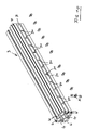
- the carrying device 1 described in FIGS. 1 to 3 serves for attachment to robot arms and for the connection of tools, such as clamping devices, gripping devices, suction devices and other aids, such as valves, sensors or the like.
- the one rod 3 is vertical, the other rod 3 arranged horizontally.
- the respective rod 3 is a substantially circular cross-section having hollow profile.
- grooves 4 are arranged, which are formed as undercut grooves. Between adjacent grooves 4, the rod 3 has a cavity 5, furthermore, the rod is provided with a central cavity 6.
- the cavities 5 and 6 also extend over the entire length of the rod.
- the undercut grooves 4 serve to receive clamping pieces 7, wherein the respective clamping piece 7 is provided with two threaded holes 8.
- the part 9 is formed in the region of its upper end as a half-shell 15, which serves to receive the upper rod 3.
- the bearing element 2 has a second part 16, which is designed in accordance with a half shell and is provided with two holes which serve to receive screws 17.
- the half shell 15 of the first part 9 associated leg 18 are provided with threaded holes 19 for receiving the threaded portions of the screws 17.
- the part 9 has a recess 20 in the region of the two legs 18 and the connecting web 22, so that in the region of the outer contour of the part 9 in this area a projecting, U-shaped edge 21 is formed.
- the recess 20 serves to receive a cover plate which is designed U-shaped according to the arrangement of the two legs 18 and the web 22.
- the cover plate 23 is provided with two holes for the passage of screws 24 which are screwed into threaded bores 25 in the region of the transitions from the legs 18 to the web 22.
- the cover plate 24 is provided with a scaling 27 in the region of the circular edge 26.
- the cover plate 23 is provided with ratchet teeth 35.
- a positioning member 28 cooperates, which is clamped between the cover plate 23 and the part 9 in the region of the recess 20.
- the positioning member 28 has a disc portion 29 with ratchet teeth 30, which cooperate with the locking teeth 35 of the cover plate 23. This makes it possible to arrange the positioning member 28 in different positions with respect to the cover plate 23, thus with respect to the half-shell 15 in a form-fitting manner.
- the positioning member 28 further includes a, relative to the circular arc-shaped curvature of the disc portion 29, radially inwardly facing further disc portion 31. This is formed as a plate and connected via a predetermined breaking line 32 with the disc portion 29.
- the disk section 31, starting from the predetermined breaking line 32, has a scale line 33. Consequently, the position of the positioning member 28 with respect to the scale 27 of the cover plate 23 in a simple manner with a view of the cover plate 23 can be seen from the outside.
- the ratchet teeth 35 of the cover plate 23 extend over an angle of almost 180 °. This allows a permanently latched pivoting of the positioning member 28 with respect to the cover plate 23 of about 100 ° reach, namely, starting from a neutral position, respectively by 50 ° clockwise and 50 ° counterclockwise.
- Figures 4 to 6 differs from that of Figures 1 to 3 essentially in that the lower vertical rod 3, corresponding to the upper, horizontal rod 3, due to a lower rod 3 associated positioning member 28 in any Positions can be positioned.
- components according to this embodiment which are the same as those of the first embodiment are designated by the same reference numerals. This also applies to the later discussion of the other embodiments.
- the projection 10 of the part 9 of the bearing element 2 corresponding to the half-shell 15, which is formed by the two legs 18 and the connecting web 22 is formed, and it is this area with a return, respectively the recess 20, provided for receiving cover plate 23 and positioning member 28, the latter engages in the clamping piece 7, that is clamped to the vertically arranged lower rod 3.
- a second part 16 of the bearing element 2 is provided which can be screwed by means of screws 17 with the projection 10, so that the lower rod 3 between this part 16 and the neck 10 is clamped.
- the portion 31 of the positioning member 28 designed as a pin with predetermined breaking point 32, the pin 31 in the circular cross-section, the pin adapted opening 34 of the clamping piece 7 engages.
- the bearing element 2 serves to support a horizontally arranged lower bar 3 having a square cross-section and an upper horizontally arranged bar 3 arranged perpendicular to the lower bar and having the circular cross-section discussed above.
- the lower rod 3 is also formed as a profile bar. In the region of the corners of the hollow profile four extending over the length of the rod 3 grooves 4 are provided. Four further grooves 4 also extend over the length of the rod 3, they are arranged in the region of a side surface of the rod 3, thus each between two corner grooves 4.
- the grooves are each formed as undercut grooves and serve to receive the threaded holes 12 having clamping pieces 13.
- the bearing element is formed in four parts. There are two L-shaped parts 36 are provided, each of which leg 37 and 38 has two holes, which are penetrated by two screws 11. The screws are loosely screwed into the clamping pieces 13.
- the two legs 37 of the parts 36 overlap slightly, so that due to the shorter design of the clamping pieces located there 13 these can be inserted into the common, lower, middle groove 4 of the lower rod 3.
- the two other clamping pieces 13, which are associated with the legs 38 inserted into the lateral, central grooves 4 of the rod 3. Due to the recesses 39 of the two legs 37 of the parts 36 they can be positioned against each other, so that when tightening the clamping pieces 13 which are associated with the parts 36, these are firmly clamped to the lower rod 3.
- the legs 38 are designed in the region of their upper ends corresponding to the half-shell 15 described for the first embodiment, thus have the two legs 18, the connecting web 22 and the recess 20 on.
- the cover plate 23 is used, with arranged between the cover plate and the return positioning member 28.
- two positioning parts for the upper rod 3 are provided. Accordingly, this rod is clamped by means of two parts 16 and associated screws 17.
- This embodiment thus describes a cross clamp with different profiles, on the one hand a square, stronger profile, on the other hand a circle cross-section exhibiting weaker profile, the weaker profile can be positioned to the above 100 °, based on a pivoting with respect to the longitudinal axis of the upper rod 3.
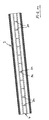
- FIGS. 10 to 12 shows that, in particular for the application of the profile with a rectangular cross-section, the groove of the rod 3, for example the illustrated center groove, can accommodate a clamping piece 7 of particularly long length. It is clamped on unspecified clamping means, in particular screws, with the rod 3, or connected to this in a defined position, for. B. riveted.
- the clamping piece 13 has a plurality of slots 34, which are arranged in particular at a distance of 50 mm. This makes it possible positioning parts 28 and thus bearing elements 2, which receive the positioning members 28, in a certain grid spacing with respect to the rod 3. On This way is a quick positioning of the bearing elements 2 at different locations, but based on the actual grid spacing, possible.
- the part 36 is provided with a front-side cutout 40 in the region of the transition from the leg 37 to the leg 38.
- This serves to receive the positioning part 28 shown in FIG. 12, which is provided with the predetermined breaking point 32 as a leaflet.
- the positioning member 28 is applied in the region of its one half 41 to the base of the cutout 40, which is provided there with a threaded bore.
- the half 41 of the positioning part 28 is provided with a hole, so that the positioning part can be fastened by means of a screw in the region of the cutout 40.
- This positioning part 28 is thus assigned to the groove 4 arranged in the region of a corner of the profile.
- This groove 4 accommodates the particularly long clamping piece 7 illustrated in FIG. 12, which is positioned in a defined manner and clamped to the rod 3.
- the parts 36 engages the other half 42 of the positioning member 28 in the slot 34 of the clamping piece 7 a.
Landscapes
- Engineering & Computer Science (AREA)
- General Engineering & Computer Science (AREA)
- Mechanical Engineering (AREA)
- Robotics (AREA)
- Clamps And Clips (AREA)
Abstract
Description
Die Erfindung betrifft eine Trageinrichtung, insbesondere zur Anbringung an Roboterarmen und für die Anbindung von Werkzeugen, wie Spann-, Greif-, Saugeinrichtungen und sonstigen Hilfsmitteln, wie Ventilen, Sensoren oder dergleichen.The invention relates to a carrying device, in particular for attachment to robot arms and for the connection of tools, such as clamping, gripping, suction and other tools, such as valves, sensors or the like.
Eine solche Trageinrichtung ist aus der EP 1 041 295 A1 bekannt. Sie weist mindestens zwei Stangen auf, die durch an das Profil der Stangen angepasste, mindestens zweiteilige Klemmstücke lösbar miteinander verbindbar sind. Die jeweilige Stange ist mit mindestens einer hinterschnittenen Nut versehen. In der Nut ist eine in dieser verspannbaren Justierleiste angeordnet. Sowohl im Klemmstück als auch in der Justierleiste sind Justierbohrungen angeordnet. Diese können durch relatives Verschieben von Justierleiste und Klemmstück in eine fluchtende Anordnung gebracht werden. In dieser Position dienen sie der Aufnahme eines Justierstiftes.Such a carrying device is known from
Mit einer solchen Trageinrichtung lassen sich Justierungsvorgaben zunächst unabhängig von den Klemmstücken an den Stangen vornehmen und es sind dann die Klemmstücke orientiert in den eingestellten Positionen platzier- und fixierbar. Nach abgeschlossener Positionierung des Klemmstücks wird der Justierstift entfernt.With such a support adjustment requirements can initially make independent of the clamping pieces on the rods and then it is the clamping pieces oriented placed and fixed in the set positions. After completion of positioning of the clamping piece of the adjusting pin is removed.
Nachteilig ist bei der bekannten Trageinrichtung, dass eine durch äußere Kräfte, beispielsweise, bei einer Fehlfunktion des Roboters, bewirkte Verschiebung von Klemmstück und Justierleiste nicht von außen erkannt werden kann. Des weiteren besteht keine Möglichkeit, die Klemmstücke in unterschiedlichen Winkelpositionen bezüglich der Stange zu positionieren.A disadvantage of the known support means that caused by external forces, for example, in a malfunction of the robot, caused displacement of clamping piece and adjusting bar can not be detected from the outside. Furthermore, there is no possibility to position the clamping pieces in different angular positions with respect to the rod.
Aufgabe der Erfindung ist es, eine Trageinrichtung zu schaffen, bei der das Lagerelement und die Stange eindeutig zueinander positionierbar sind, und eine ungewollte Verschiebung der Stange, insbesondere in deren Längsrichtung, bezüglich des Lagerelements unmittelbar erkannt werden kann.The object of the invention is to provide a support device in which the bearing element and the rod are clearly positioned to each other, and an unwanted displacement of the rod, in particular in the longitudinal direction, with respect to the bearing element can be detected directly.
Die Erfindung schlägt zur Lösung dieser Aufgabe eine Trageinrichtung vor, insbesondere zur Anbringung an Roboterarmen und für die Anbindung von Werkzeugen, wie Spann-, Greif-, Saugeinrichtungen und sonstigen Hilfsmitteln, wie Ventilen, Sensoren oder dergleichen, mit einem mindestens zweiteiligen Lagerelement und einer im Lagerelement zwischen den Lagerelementteilen klemmend gehaltenen, profilierten Stange, wobei die Stange mit mindestens einer hinterschnittenen Nut versehen ist, sowie die Stange mindestens ein in Längsrichtung der Nut positionierbares und mit der Stange verspannbares Klemmstück aufnimmt, wobei das Klemmstück eine Öffnung aufweist, ein mit dem Lagerelement verbundenes Positionierteil in die Öffnung eingreift, sowie das Positionierteil mit einer Sollbruchstelle versehen ist.The invention proposes to solve this problem, a support device, in particular for attachment to robot arms and for the connection of tools such as clamping, gripping, suction and other aids, such as valves, sensors or the like, with an at least two-part bearing element and a in Clamping bearing element between the bearing element parts held, profiled rod, wherein the rod is provided with at least one undercut groove, and the rod at least one positionable in the longitudinal direction of the groove and bracing with the rod clamping piece, wherein the clamping piece has an opening, a positioning member connected to the bearing member in the opening engages, and the positioning member is provided with a predetermined breaking point.
Wesentlich ist bei der erfindungsgemäßen Trageinrichtung, dass das Klemmstück eine Öffnung aufweist, in das das mit dem Lagerelement verbundene Positionierteil eingreift. Bei diesem Positionierteil kann es sich um ein beliebig gestaltetes Formteil handeln. Es ist insbesondere daran gedacht, dass das Positionierteil als plattenförmiges Teil oder Stift ausgebildet ist. Die Sollbruchstelle des Positionierteils kann auf unterschiedliche Art und Weise bewerkstelligt werden. Sinn und Zweck der Gestaltung des Positionierteils mit der Sollbruchstelle ist es, dass, bei Einwirkung nicht gewünschter, erhöhter Kräfte zwischen Klemmstück und Lagerelement das Positionierteil beschädigt wird, insbesondere bricht, so dass diese Veränderung des Positionierteils die Verlagerung von Klemmstück und Lagerelement anzeigt. Damit ist ohne weiteres von außen eine Fehlfunktion, insbesondere eine ungewollte Bewegung des Roboters oder eine ungewollte Bewegung des Werkstücks, das dem Roboter zugeführt wird, ersichtlich.It is essential in the carrying device according to the invention that the clamping piece has an opening into which engages the positioning member connected to the bearing element. This positioning part can be an arbitrarily designed molded part. It is especially thought that the positioning part is formed as a plate-shaped part or pin. The predetermined breaking point of the positioning part can be accomplished in different ways. The purpose of the design of the positioning member with the predetermined breaking point is that, when acting unwanted, increased forces between clamping piece and bearing element, the positioning is damaged, in particular breaks, so that this change in the positioning indicates the displacement of clamping piece and bearing element. This is readily apparent from the outside a malfunction, in particular an unwanted movement of the robot or an unwanted movement of the workpiece, which is supplied to the robot can be seen.
In aller Regel ist die Sollbruchstelle als Dünnstelle des Positionierteils im Übergang vom Lagerelement zum Klemmstück ausgebildet. In diesem Bereich wird das Positionierteil bei einer Fehlfunktion somit brechen. Durch die Schaffung der definierten Bruchstelle wird verhindert, dass bei einer Fehlfunktion das Klemmstück oder das Lagerelement beschädigt werden.As a rule, the predetermined breaking point is formed as a thin point of the positioning in the transition from the bearing element to the clamping piece. In this area, the positioning will break part of a malfunction. The creation of the defined breaking point prevents the clamping piece or the bearing element from being damaged in the event of a malfunction.
Wesentlich ist bei der Erfindung ferner, dass das Positionierteil dauerhaft, somit während des Betriebs der Trageinrichtung, mit dem Lagerelement als auch mit dem Klemmstück zusammenwirkt.It is also essential in the invention that the positioning permanently, thus cooperating during operation of the support means, with the bearing element and with the clamping piece.
Bei Ausbildung des Positionierteils als plattenförmiges Bauteil ist die Öffnung im Klemmstück insbesondere als quer zur Längserstreckung des Klemmstücks bzw. der Längserstreckung der Nut angeordneter Schlitz ausgebildet. Das Positionierteil ist dabei im wesentlichen spielfrei in die Öffnung im Klemmstück einsteckbar. Dies bedeutet, dass das Positionierteil nicht nur bei einer Längsverschiebung zwischen Klemmstück und Lagerelement bricht, sondern auch bei einer ungewollten Relativ-Drehbewegung dieser Teile, somit einer Bewegung der Teile um die Längsachse der Stange.When the positioning part is designed as a plate-shaped component, the opening in the clamping piece is designed in particular as a slot arranged transversely to the longitudinal extension of the clamping piece or the longitudinal extent of the groove. The positioning part is inserted substantially free of play in the opening in the clamping piece. This means that the positioning member breaks not only in a longitudinal displacement between clamping piece and bearing element, but also in an unwanted relative rotational movement of these parts, thus a movement of the parts about the longitudinal axis of the rod.
Grundsätzlich könnte das Positionierteil eine bauliche Einheit mit dem Lagerelement, insbesondere mit einem Lagerelementteil bilden. Gemäß einer bevorzugten Ausführungsform der Erfindung ist aber vorgesehen, dass das Positionierteil als separates Bauteil ausgebildet ist, das mittels Befestigungsmitteln mit dem Lagerelement verbindbar ist. Die Befestigung des Positionierteils am Lagerelement erfolgt insbesondere durch Schrauben.In principle, the positioning part could form a structural unit with the bearing element, in particular with a bearing element part. According to a preferred embodiment of the invention, however, it is provided that the positioning part is formed as a separate component, which is connectable by means of fastening means with the bearing element. The attachment of the positioning on the bearing element is done in particular by screws.
Die Ausbildung des Positionierteils als separates Bauteil ermöglicht ein wesentlich größeres Spektrum der Positionierung von Lagerelement und Stange. So ist insbesondere vorgesehen, dass das Positionierteil einen Scheibenabschnitt mit Rastierungen aufweist und das Lagerelement mit komplementären Rastierungen versehen ist. Dies geschieht zum Positionieren des Positionierteils in unterschiedlichen Positionen, insbesondere unterschiedlichen Winkelpositionen, bezüglich des Lagerelements. Der Scheibenabschnitt ist zweckmäßig kreisbogenförmig gestaltet und es greift ein weiterer Scheibenabschnitt des Positionierteils in die Öffnung des Klemmstücks ein. Mit dem Lagerelement ist insbesondere eine Deckplatte verbindbar, insbesondere verschraubbar, wobei die Deckplatte auf ihrer dem Lagerelement zugewandten Seite die komplementäre Rastierung aufweist und das Positionierteil zwischen der Deckplatte und dem Lagerelement geklemmt ist.The formation of the positioning part as a separate component allows a much wider range of positioning of the bearing element and rod. It is thus provided in particular that the positioning part has a disk section with detents and the bearing element is provided with complementary detents. This is done for positioning the positioning part in different positions, in particular different angular positions, with respect to the bearing element. The disc portion is expedient circular arc designed and it engages another disc portion of the positioning part in the opening of the clamping piece. With the bearing element in particular a cover plate is connectable, in particular screwed, wherein the cover plate on its side facing the bearing element has the complementary detent and the positioning part is clamped between the cover plate and the bearing element.
Somit kann das Positionierteil in unterschiedlichen Winkelpositionen bezüglich des Lagerelements angeordnet und in der jeweiligen gewünschten Winkelposition mittels der Deckplatte fixiert werden. Das Lagerelement kann damit die Stangen in unterschiedlichen Winkelstellungen, bezogen auf deren Längsachse, positioniert aufnehmen. Dies steigert die Variabilität der Trageinrichtung erheblich und ermöglicht eine sehr flexible Anbindung an den Roboter bzw. an die Werkzeuge und sonstige Hilfsmittel.Thus, the positioning can be arranged in different angular positions with respect to the bearing element and in the respective desired angular position be fixed by means of the cover plate. The bearing element can thus record the rods in different angular positions, with respect to their longitudinal axis, positioned. This considerably increases the variability of the carrying device and allows a very flexible connection to the robot or to the tools and other aids.
Es wird als besonders vorteilhaft angesehen, wenn sich die Rastierung über einen solchen Winkel erstreckt, dass die Stange bezüglich deren Längsachse um einen Winkel von bis zu 100° schwenkbar ist.It is considered to be particularly advantageous if the detent extends over such an angle that the rod is pivotable with respect to its longitudinal axis by an angle of up to 100 °.
Eine bevorzugte Weiterbildung der Erfindung sieht vor, dass das Lagerelement der Aufnahme von mehreren, insbesondere der Aufnahme von zwei Stangen dient. Insbesondere sind mindestens zwei Stangen im rechten Winkel zueinander angeordnet. Insbesondere ist in jedem Lagerungsbereich der jeweiligen Stange im Lagerelement das vorgeschriebene Positionierteil zugeordnet. Hiermit stellt sich die Trageinrichtung, auf alle Stangen bezogen, äußerst flexibel dar.A preferred development of the invention provides that the bearing element of the recording of several, in particular the inclusion of two rods is used. In particular, at least two rods are arranged at right angles to each other. In particular, the prescribed positioning part is assigned in each storage area of the respective bar in the bearing element. Hereby, the carrying device, based on all rods, is extremely flexible.
Die jeweilige bei der Trageinrichtung Verwendung findende Stange weist im wesentlichen Kreisquerschnitt oder rechteckigen Querschnitt, insbesondere quadratischen Querschnitt auf.The respective rod used in the carrying device has a substantially circular cross section or rectangular cross section, in particular a square cross section.
Gemäß einer bevorzugten Ausbildung ist vorgesehen, dass eine erste Stange zwischen zwei miteinander verbundenen Montagewinkeln klemmend gehalten ist und mit den Montagewinkeln Spannstücke verbunden sind, wobei zwischen den Spannstücken und den Montagewinkeln die zweite Stange klemmend gehalten ist.According to a preferred embodiment it is provided that a first rod is clamped between two interconnected mounting brackets and clamping pieces are connected to the mounting brackets, wherein the second rod is clamped between the clamping pieces and the mounting brackets.
Gemäß einer anderen bevorzugten Variante ist vorgesehen, dass eine erste Stange zwischen einem Montageelement und einem ersten Spannstück klemmend gehalten ist und eine zweite Stange zwischen dem Montagelement und einem zweiten Spannstück klemmend gehalten ist.According to another preferred variant it is provided that a first rod between a mounting member and a first clamping piece is clamped and a second rod between the mounting member and a second clamping piece is clamped.
Gemäß einer dritten bevorzugten Variante ist vorgesehen, dass eine erste Stange zwischen einem Montageelement und einem ersten Spannstück klemmend gehalten ist und eine zweite Stange über Kulissensteine klemmend in dem Montagelement gehalten ist. Im Bereich der Kulissensteine findet somit kein Positionierteil Verwendung.According to a third preferred variant, provision is made for a first rod to be clamped between a mounting element and a first clamping piece and a second rod to be clamped in the mounting element via sliding blocks. Thus, no positioning part is used in the area of the sliding blocks.
Das jeweilige Klemmstück ist insbesondere als Nutenstein ausgebildet. Eine besondere Weiterbildung der Erfindung sieht vor, dass das jeweilige Klemmstück mit mehreren Öffnungen versehen ist. Dieses Klemmstück weist somit eine sehr große Länge auf, erstreckt sich unter Umständen über die Länge der Stange. Ein solches Klemmstück weist insbesondere Öffnungen in einem Abstand von 50 mm auf. Dies ermöglicht es, bei einmaliger Positionierung des Klemmstücks in der Stange unmittelbar eine Vielzahl von Lagerelementen bezüglich der Öffnungen im Klemmstück auszurichten.The respective clamping piece is designed in particular as a sliding block. A particular embodiment of the invention provides that the respective clamping piece is provided with a plurality of openings. This clamping piece thus has a very long length, may extend over the length of the rod. Such a clamping piece has in particular openings at a distance of 50 mm. This makes it possible to align with a single positioning of the clamping piece in the rod immediately a plurality of bearing elements with respect to the openings in the clamping piece.
Die Stange kann an unterschiedlichen Stellen mit den Nuten zur Aufnahme der Klemmstücke versehen sein. Die Nuten sind im Bereich der Seitenflächen der Stange oder, bei eckiger Ausbildung der Stangen durchaus auch im Bereich der Ecken angeordnet.The rod may be provided at different locations with the grooves for receiving the clamping pieces. The grooves are arranged in the region of the side surfaces of the rod or, in the case of angular formation of the rods, also in the region of the corners.
Weitere Merkmale der Erfindung sind in den Unteransprüchen, der Beschreibung der Figuren und den Figuren selbst dargestellt, wobei bemerkt wird, dass alle Einzelmerkmale und alle Kombinationen von Einzelmerkmalen erfindungswesentlich sind.Further features of the invention are set forth in the subclaims, the description of the figures and the figures themselves, wherein it is noted that all individual features and all combinations of individual features are essential to the invention.
In den Figuren ist die Erfindung anhand diverser Ausführungsformen beispielsweise dargestellt, ohne auf diese beschränkt zu sein. Es stellt dar:
- Figur 1:
- eine erste Ausführungsform der erfindungsgemäßen Trageinrichtung, veranschaulicht in einer räumlichen Ansicht,
- Figur 2:
- eine Ansicht der in
Figur 1 gezeigten Trageinrichtung, in Längsrichtung der horizontalen Stange gesehen, - Figur 3:
- eine Explosionsdarstellung der in den
Figuren 1 und 2 gezeigten Trageinrichtung, in einer räumlichen Ansicht gesehen, - Figur 4:
- eine zweite Ausführungsform der erfindungsgemäßen Trageinrichtung, veranschaulicht in einer räumlichen Ansicht,
- Figur 5:
- eine Ansicht der in
Figur 4 gezeigten Trageinrichtung, in Längsrichtung der horizontalen Stange gesehen, - Figur 6:
- eine Explosionsdarstellung der in
den Figuren 4 und 5 gezeigten Trageinrichtung, in einer räumlichen Ansicht gesehen, - Figur 7:
- eine dritte Ausführungsform der erfindungsgemäßen Trageinrichtung, veranschaulicht in einer räumlichen Ansicht,
- Figur 8:
- eine Ansicht der in
Figur 7 gezeigten Trageinrichtung, in Richtung der Längsachse der oberen horizontalen Stange gesehen, - Figur 9:
- eine Explosionsdarstellung der in
den Figuren 7 und 8 gezeigten Trageinrichtung, in einer räumlichen Ansicht gesehen, - Figur 10:
- eine räumliche Ansicht der bei der dritten Ausführungsform Verwendung findenden unteren, horizontalen Stange, mit modifiziertem, langem in eine Nut der Stange eingesetztem Klemmstück sowie diversen Positionierteilen, in einer räumlichen Ansicht,
- Figur 11:
- eine Draufsicht der Anordnung gemäß Figur 10 und
- Figur 12:
- eine räumliche Ansicht des in
den Figuren 10 und 11 gezeigten Klemmstücks und der diversen Positionierteile.
- FIG. 1:
- A first embodiment of the carrying device according to the invention, illustrated in a three-dimensional view,
- FIG. 2:
- 1 shows a view of the carrying device shown in FIG. 1, viewed in the longitudinal direction of the horizontal bar,
- FIG. 3:
- an exploded view of the support device shown in Figures 1 and 2, seen in a three-dimensional view,
- FIG. 4:
- A second embodiment of the carrying device according to the invention, illustrated in a three-dimensional view,
- FIG. 5:
- 4 shows a view of the carrying device shown in FIG. 4, seen in the longitudinal direction of the horizontal bar,
- FIG. 6:
- 7 is an exploded view of the support device shown in FIGS. 4 and 5, seen in a three-dimensional view,
- FIG. 7:
- A third embodiment of the carrying device according to the invention, illustrated in a three-dimensional view,
- FIG. 8:
- 7 shows a view of the carrying device shown in FIG. 7, seen in the direction of the longitudinal axis of the upper horizontal bar,
- FIG. 9:
- 4 is an exploded view of the support device shown in FIGS. 7 and 8, seen in a three-dimensional view,
- FIG. 10:
- a spatial view of the use in the third embodiment, the lower horizontal rod, with modified, long inserted into a groove of the rod clamping piece and various positioning parts, in a three-dimensional view,
- FIG. 11:
- a plan view of the arrangement according to Figure 10 and
- FIG. 12:
- a spatial view of the clamping piece shown in Figures 10 and 11 and the various positioning parts.
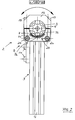
Die in den Figuren 1 bis 3 beschriebene Trageinrichtung 1 dient der Anbringung an Roboterarmen und für die Anbindung von Werkzeugen, wie Spann-, Greif-, Saugeinrichtungen und sonstigen Hilfsmitteln, wie Ventilen, Sensoren oder dergleichen.The carrying
Sie weist ein zweiteiliges Lagerelement 2 sowie zwei im rechten Winkel zueinander angeordnete, im Lagerelement klemmend gehaltene, profilierte Stangen 3 auf. Bezogen auf die Orientierung der Figuren 1 bis 3 ist die eine Stange 3 vertikal, die andere Stange 3 horizontal angeordnet. Bei der jeweiligen Stange 3 handelt es sich um ein im wesentlichen kreisförmigen Querschnitt aufweisendes Hohlprofil. Am Umfang der jeweiligen Stange 3 sind vier sich über die Länge der Stange 3 erstreckende Nuten 4 angeordnet, die als hinterschnittene Nuten ausgebildet sind. Zwischen benachbarten Nuten 4 weist die Stange 3 einen Hohlraum 5 auf, ferner ist die Stange mit einem zentralen Hohlraum 6 versehen. Die Hohlräume 5 und 6 erstrecken sich gleichfalls über die gesamte Länge der Stange. Die hinterschnittenen Nuten 4 dienen der Aufnahme von Klemmstücken 7, wobei das jeweilige Klemmstück 7 mit zwei Gewindebohrungen 8 versehen ist. Mittels dieser Klemmstücke 7 erfolgt über geeignete Mittel die Anbringung an Roboterarmen oder die Anbindung von Werkzeugen.It has a two-
Demgegenüber betrifft die vorliegende Erfindung die Verbindung, Lagerung und besondere Positionierung der beiden Stangen 3 aneinander:
Die vertikale Stange 3 ist in einem ersten Teil 9 des Lagerelements 2 gehalten.Dieses Teil 9 weist einen Winkelansatz 10 zur Anlage derStange 3 im Bereich zweier der vier Nuten 4 dieser Stange auf. Jedem Schenkel desAnsatzes 10 sind zwei übereinander angeordnete Bohrungen zugeordnet. Diesedurchsetzen Schrauben 11, die inGewindebohrungen 12von zwei Klemmstücken 13 eingeschraubt sind. Beirelativ gelösten Schrauben 11 wird die vertikaleStange 3 indas Teil 9 eingeschoben,wobei die Klemmstücke 13 in die zugeordneten beiden Nuten 4 eingreifen undein Zentrierzapfen 14 desTeils 9 in den kreisförmigenQuerschnitt aufweisenden Hohlraum 6 eingreift. Dann werden dieSchrauben 11 angezogen, womit die feste Verbindung zwischen untererStange 3und Teil 9 bewirkt wird.
- The
vertical rod 3 is held in afirst part 9 of thebearing element 2. Thispart 9 has anangle lug 10 for abutment of therod 3 in the region of two of the fourgrooves 4 of this rod. Each leg of theprojection 10 are assigned two superimposed holes. These enforce screws 11 which are screwed into threadedholes 12 of two clampingpieces 13. With relativelyloose screws 11, thevertical bar 3 inserted into thepart 9, wherein the clampingpieces 13 engage in the associated twogrooves 4 and a centeringpin 14 of thepart 9 engages in thecircular cross-section cavity 6. Then thescrews 11 are tightened, whereby the firm connection between thelower rod 3 andpart 9 is effected.
Das Teil 9 ist im Bereich seines oberen Endes als Halbschale 15 ausgebildet, die der Aufnahme der oberen Stange 3 dient. Zum Fixieren der oberen Stange 3 weist das Lagerelement 2 ein zweites Teil 16 auf, das entsprechend halbschalenförmig gestaltet ist und mit zwei Bohrungen versehen ist, die der Aufnahme von Schrauben 17 dienen. Die der Halbschale 15 des ersten Teils 9 zugeordneten Schenkel 18 sind mit Gewindebohrungen 19 zur Aufnahme der Gewindeabschnitte der Schrauben 17 versehen.The
Das Teil 9 weist im Bereich der beiden Schenkel 18 und des diese verbindenden Stegs 22 einen Rücksprung 20 auf, so dass im Bereich der Außenkontur des Teils 9 in diesem Bereich ein vorstehender, U-förmiger Rand 21 gebildet ist.The
Der Rücksprung 20 dient der Aufnahme einer Deckplatte, die entsprechend der Anordnung der beiden Schenkel 18 und des Stegs 22 U-förmig gestaltet ist. Die Deckplatte 23 ist mit zwei Bohrungen zum Durchstecken von Schrauben 24 versehen, die in Gewindebohrungen 25 im Bereich der Übergänge von den Schenkeln 18 zum Steg 22 einschraubbar sind. Außen ist die Deckplatte 24 im Bereich des kreisförmigen Randes 26 mit einer Skalierung 27 versehen. Auf der der Skalierung 27 abgewandten Seite der Deckplatte 24, somit auf der Seite, die dem Rücksprung 20 zugewandt ist, ist die Deckplatte 23 mit Rastzähnen 35 versehen.The
Mit diesen Rastzähnen 35 wirkt ein Positionierteil 28 zusammen, das zwischen die Deckplatte 23 und das Teil 9 im Bereich des Rücksprungs 20 eingeklemmt wird. Das Positionierteil 28 weist einen Scheibenabschnitt 29 mit Rastzähnen 30 auf, die mit den Rastzähnen 35 der Deckplatte 23 zusammenwirken. Dies ermöglicht es, das Positionierteil 28 in unterschiedlichen Stellungen bezüglich der Deckplatte 23, somit bezüglich der Halbschale 15 formschlüssig anzuordnen. - Das Positionierteil 28 weist ferner einen, bezogen auf die kreisbogenförmige Krümmung des Scheibenabschnitts 29, radial nach innen weisenden weiteren Scheibenabschnitt 31 auf. Dieser ist als Plättchen ausgebildet und über eine Sollbruchlinie 32 mit dem Scheibenabschnitt 29 verbunden. In einem zentralen Bereich weist der Scheibenabschnitt 31, von der Sollbruchlinie 32 ausgehend, einen Skalenstrich 33 auf. Demzufolge ist die Position des Positionierteils 28 bezüglich der Skalierung 27 der Deckplatte 23 auf einfache Art und Weise mit Blick auf die Deckplatte 23 von außen zu erkennen.With these latching
Die horizontale Stange 3 nimmt ein in Längsrichtung einer der Nuten 4 verspannbares Klemmstück 7 auf. In die beiden Gewindebohrungen 8 dieses Klemmstücks 7 werden zwei Schrauben, insbesondere Madenschrauben, eingeschraubt, die sich am Grund der Nut 4 abstützen und damit das Klemmstück 7 gegen den Hinterschnitt verspannen. Dieses ist somit in Längsrichtung der Nut fixiert. Das Klemmstück 7 weist zusätzlich, quer zu dessen Längserstreckung, einen Schlitz 34 auf, der das Klemmstück 7 beispielsweise durchsetzt. Montiert wird die obere Stange 3 mit dem in dieser verspannten Klemmstück 7 wie folgt:
- Zunächst
wird das Positionierteil 28 zwischen der Deckplatte 23und dem Teil 9 angeordnet und dieDeckplatte 23 mittels derSchrauben 24 lose befestigt. Dannwird das Positionierteil 28 in die gewünschte Winkelposition relativ zur Deckplatte 23 gebracht und es werden die beidenSchrauben 24 angezogen, so dassdas Positionierteil 28 fest zwischen der Deckplatte 23und dem Teil 9 geklemmt ist. Dann wird dieobere Stange 3 mit dem mit dieser verklemmten Klemmstück 7 indie Halbschale 15 eingelegt, derart, dass derScheibenabschnitt 31 des Positionierteils 28 inden Schlitz 34 desKlemmstücks 7 eingeführt wird. An sichwird das Teil 16 des Lagerelements 2 auf das andere Teil 9 des Lagerelements aufgesetzt und mittels der beidenSchrauben 17 verschraubt. Damit ist dieobere Stange 3 definiert - winkelorientiert bezüglich der Längsachse der oberen Stange 3 -im Lagerelement 2 gelagert. Die Winkellage kann auf einfache Art und Weise variiert werden, indem dieSchrauben 17und 24 etwas gelöst unddas Positionierteil 28 bezüglich der Deckplatte 23 verschwenkt wird. Anschließend werden diese Schrauben wieder angezogen. Es ist so eine starre Verbindung zwischen obererStange 3 und Lagerelement 2 bewerkstelligt, bei eindeutiger Positionierung der Stange in deren Längsrichtung und bezüglich deren Verdrehung, wegen des im wesentlichen spielfreien Eingriffs des Scheibenabschnitts 31 inden Schlitz 34 des Klemmstücks.
- First, the positioning
member 28 is disposed between thecover plate 23 and thepart 9 and thecover plate 23 by means of thescrews 24 loosely attached. Then, the positioningmember 28 is brought into the desired angular position relative to thecover plate 23 and the twoscrews 24 are tightened, so that the positioningmember 28 is firmly clamped between thecover plate 23 and thepart 9. Then, theupper rod 3 is inserted with the clamped with thisclamping piece 7 in the half-shell 15, such that thedisc portion 31 of the positioningmember 28 is inserted into theslot 34 of theclamping piece 7. In itself, thepart 16 of thebearing element 2 is placed on theother part 9 of the bearing element and screwed by means of the twoscrews 17. Thus, theupper rod 3 is defined - angularly oriented with respect to the longitudinal axis of the upper rod 3 - stored in thebearing element 2. The angular position can be varied in a simple manner by loosening thescrews positioning part 28 is pivoted with respect to thecover plate 23. Subsequently, these screws are tightened again. It is accomplished as a rigid connection between theupper rod 3 andbearing element 2, with clear positioning of the rod in the longitudinal direction and with respect to its rotation, because of the substantially backlash-free engagement of thedisc portion 31 in theslot 34 of the clamping piece.
Die Rastzähne 35 der Deckplatte 23 erstrecken sich über einen Winkel von nahezu 180°. Es lässt sich hierdurch eine dauerhaft rastierte Verschwenkbarkeit des Positionierteils 28 bezüglich der Deckplatte 23 von etwa 100° erreichen, nämlich, ausgehend von einer neutralen Stellung, jeweils um 50° im Uhrzeigersinn und 50° entgegen dem Uhrzeigersinn.The
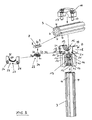
Die Ausführungsform nach den Figuren 4 bis 6 unterscheidet sich von derjenigen nach den Figuren 1 bis 3 im wesentlichen dadurch, dass auch die untere, vertikale Stange 3, entsprechend der oberen, horizontalen Stange 3, aufgrund eines der unteren Stange 3 zugeordneten Positionierteils 28 in beliebigen Stellungen positionierbar ist. Insofern sind Bauteile gemäß dieser Ausführungsform, die mit solchen der ersten Ausführungsform übereinstimmen, mit denselben Bezugsziffern bezeichnet. Dies gilt auch für die spätere Erörterung der anderen Ausführungsformen.The embodiment of Figures 4 to 6 differs from that of Figures 1 to 3 essentially in that the lower
Bei der Ausführungsform nach den Figuren 4 bis 6 ist der Ansatz 10 des Teils 9 des Lagerelements 2 entsprechend der Halbschale 15, die durch die beiden Schenkel 18 und den diese verbindenden Steg 22 gebildet ist, gestaltet und es ist dieser Bereich mit einem Rücksprung, entsprechend dem Rücksprung 20, zur Aufnahme von Deckplatte 23 und Positionierteil 28 versehen, wobei letztgenanntes in das Klemmstücks 7 eingreift, dass mit der senkrecht angeordneten unteren Stange 3 verspannt ist. Entsprechend ist, genauso wie bei der oberen, horizontalen Stange 3, ein zweites Teil 16 des Lagerelements 2 vorgesehen, das mittels Schrauben 17 mit dem Ansatz 10 verschraubbar ist, so dass die untere Stange 3 zwischen diesem Teil 16 und dem Ansatz 10 geklemmt ist. Bei dieser Ausführungsform ist, bezogen auf die untere, vertikale Stange 4, der Abschnitt 31 des Positionierteils 28 als Stift mit Sollbruchstelle 32 gestaltet, wobei der Stift 31 in die Kreisquerschnitt aufweisende, dem Stift angepasste Öffnung 34 des Klemmstücks 7 eingreift.In the embodiment according to Figures 4 to 6, the
Dadurch, dass auch die untere Stange 3 um deren Längsachse um den vorgeschriebenen Winkel von 100° verschwenkbar positioniert werden kann, ergibt sich eine besonders große Flexibilität bei der Trageinrichtung. So ist nicht nur die Schwenkbarkeit der oberen Stange 3 um 100°, sondern auch der unteren Stange 3 um 100° bezüglich des Lagerelements 2 möglich.The fact that the
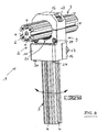
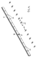
Bei der dritten Ausführungsform nach den Figuren 7 bis 9 dient das Lagerelement 2 der Lagerung einer horizontal angeordneten unteren Stange 3, die einen quadratischen Querschnitt aufweist und einer oberen horizontal angeordneten, senkrecht zur unteren Stange angeordneten Stange 3, die den vorstehend diskutierten kreisförmigen Querschnitt aufweist.In the third embodiment according to FIGS. 7 to 9, the
Die untere Stange 3 ist gleichfalls als Profilstange ausgebildet. Im Bereich der Ecken des Hohlprofils sind vier sich über die Länge der Stange 3 verlaufende Nuten 4 vorgesehen. Vier weitere Nuten 4 erstrecken sich gleichfalls über die Länge der Stange 3, sie sind im Bereich einer Seitenfläche der Stange 3, somit jeweils zwischen zwei Ecknuten 4 angeordnet. Die Nuten sind jeweils als hinterschnittene Nuten ausgebildet und dienen der Aufnahme der Gewindebohrungen 12 aufweisenden Klemmstücke 13. Bei dieser Ausführungsform ist das Lagerelement vierteilig ausgebildet. Es sind zwei L-förmige Teile 36 vorgesehen, von denen jeder Schenkel 37 bzw. 38 zwei Bohrungen aufweist, die von zwei Schrauben 11 durchsetzt sind. Die Schrauben sind in die Klemmstücke 13 lose eingeschraubt. Die beiden Schenkel 37 der Teile 36 überlappen sich etwas, so dass aufgrund der kürzeren Gestaltung der dort befindlichen Klemmstücke 13 diese in die gemeinsame, untere, mittlere Nut 4 der unteren Stange 3 eingeschoben werden können. Gleichzeitig werden die beiden anderen Klemmstücke 13, die den Schenkeln 38 zugeordnet sind, in die seitlichen, mittleren Nuten 4 der Stange 3 eingeschoben. Aufgrund der Rücksprünge 39 der beiden Schenkel 37 der Teile 36 können diese gegeneinander positioniert werden, so dass beim Anziehen der Klemmstücke 13, die den Teilen 36 zugeordnet sind, diese fest mit der unteren Stange 3 verspannt werden.The
Die Schenkel 38 sind in dem Bereich ihrer oberen Enden entsprechend der zur ersten Ausführungsform beschriebenen Halbschale 15 gestaltet, weisen somit die beiden Schenkel 18, den diese verbindenden Steg 22 und den Rücksprung 20 auf. In diesen Rücksprung ist die Deckplatte 23 einsetzbar, mit zwischen der Deckplatte und dem Rücksprung angeordnetem Positionierteil 28. Somit sind bei dieser Ausführungsform zwei Positionierteile für die obere Stange 3 vorgesehen. Entsprechend wird diese Stange mittels zweier Teile 16 und diesen zugeordneter Schrauben 17 geklemmt. Diese Ausführungsform beschreibt somit eine Kreuzklemme mit unterschiedlichen Profilen, einerseits ein quadratisches, stärkeres Profil, andererseits einen Kreisquerschnitt aufweisendes schwächeres Profil, wobei das schwächere Profil um die vorbeschriebenen 100°, bezogen auf eine Verschwenkung bezüglich der Längsachse der oberen Stange 3 positionierbar ist.The
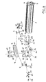
Die Ausführungsform nach den Figuren 10 bis 12 zeigt, dass, dies gilt insbesondere für den Anwendungsfall des Profils mit rechteckigem Querschnitt, die Nut der Stange 3, beispielsweise die veranschaulichte Mittelnut, ein Klemmstück 7 besonders großer Länge aufnehmen kann. Es wird über nicht näher veranschaulichte Spannmittel, insbesondere Schrauben, mit der Stange 3 verspannt, oder mit dieser in einer definierten Position verbunden, z. B. vernietet. Das Klemmstück 13 weist eine Vielzahl von Schlitzen 34 auf, die insbesondere in einem Abstand von 50 mm angeordnet sind. Dies ermöglicht es, Positionierteile 28 und damit Lagerelemente 2, die die Positionierteile 28 aufnehmen, in einem bestimmten Rasterabstand bezüglich der Stange 3 zu positionieren. Auf diese Art und Weise ist ein schnelles Positionieren der Lagerelemente 2 an unterschiedlichen Stellen, allerdings auf den konkreten Rasterabstand bezogen, möglich.The embodiment according to FIGS. 10 to 12 shows that, in particular for the application of the profile with a rectangular cross-section, the groove of the
Wie der Darstellung der Figuren 7 bis 9 bezüglich der dritten Ausführungsform zu entnehmen ist, ist das Teil 36 im Bereich des Übergangs vom Schenkel 37 zum Schenkel 38 mit einer stirnseitigen Ausfräsung 40 versehen. Diese dient der Aufnahme des in Figur 12 gezeigten Positionierteils 28, das als Blättchen mit der Sollbruchstelle 32 versehen ist. Das Positionierteil 28 wird im Bereich seiner einen Hälfte 41 an die Grundfläche der Ausfräsung 40 angelegt, die dort mit einer Gewindebohrung versehen ist. Entsprechend ist die Hälfte 41 des Positionierteils 28 mit einem Loch versehen, so dass das Positionierteil mittels einer Schraube im Bereich der Ausfräsung 40 befestigt werden kann. Dieses Positionierteil 28 ist somit der im Bereich einer Ecke des Profils angeordnete Nut 4 zugeordnet. Diese Nut 4 nimmt das in der Figur 12 veranschaulichte besonders lange Klemmstück 7 auf, das definiert positioniert ist und mit der Stange 3 verspannt ist. Beim Befestigen der Teile 36 greift die andere Hälfte 42 des Positionierteils 28 in den Schlitz 34 des Klemmstücks 7 ein.As can be seen from the illustration of FIGS. 7 to 9 with respect to the third embodiment, the
Claims (16)
Priority Applications (1)
| Application Number | Priority Date | Filing Date | Title |
|---|---|---|---|
| EP04016376A EP1617087A1 (en) | 2004-07-13 | 2004-07-13 | Supporting device |
Applications Claiming Priority (1)
| Application Number | Priority Date | Filing Date | Title |
|---|---|---|---|
| EP04016376A EP1617087A1 (en) | 2004-07-13 | 2004-07-13 | Supporting device |
Publications (1)
| Publication Number | Publication Date |
|---|---|
| EP1617087A1 true EP1617087A1 (en) | 2006-01-18 |
Family
ID=34925727
Family Applications (1)
| Application Number | Title | Priority Date | Filing Date |
|---|---|---|---|
| EP04016376A Withdrawn EP1617087A1 (en) | 2004-07-13 | 2004-07-13 | Supporting device |
Country Status (1)
| Country | Link |
|---|---|
| EP (1) | EP1617087A1 (en) |
Cited By (6)
| Publication number | Priority date | Publication date | Assignee | Title |
|---|---|---|---|---|
| WO2007120795A2 (en) * | 2006-04-13 | 2007-10-25 | Norgren Automotive, Inc. | Apparatus for accurately positioning and supporting modular tooling |
| FR2908731A1 (en) * | 2006-11-22 | 2008-05-23 | Genus Technologies Sa | Modular rigid support device for e.g. positioning automobile body part, has central part carrying spread longitudinal grooves for receiving fixation structures or strips of modular bar, where bar is removably connected to central part |
| WO2019174912A1 (en) * | 2018-03-15 | 2019-09-19 | Igus Gmbh | Manipulator having joints and multi-functional profile for same |
| EP3626898A1 (en) * | 2018-09-20 | 2020-03-25 | Rixen, Wolfgang Klaus | Profile pipe system |
| CN112735897A (en) * | 2020-12-14 | 2021-04-30 | 河南平高电气股份有限公司 | Earthing switch and interphase coupling device thereof |
| WO2022129074A1 (en) * | 2020-12-14 | 2022-06-23 | Fyx Bv | Frame with notches |
Citations (3)
| Publication number | Priority date | Publication date | Assignee | Title |
|---|---|---|---|---|
| EP1041295A1 (en) * | 1999-03-27 | 2000-10-04 | DE-STA-CO Metallerzeugnisse GmbH | Supporting device |
| DE10017897A1 (en) * | 2000-04-11 | 2001-10-25 | Tuenkers Maschinenbau Gmbh | Framework system for body construction in motor industry has cylindrical tubes interconnected in different planes or at different angles by clamps with centering and indicating pin to indicate correct relative position of tubes |
| EP1420172A1 (en) * | 2002-11-15 | 2004-05-19 | IMI NORGREN Automotive GmbH | Method for positioning clamping means on the profiled beam of a robot |
-
2004
- 2004-07-13 EP EP04016376A patent/EP1617087A1/en not_active Withdrawn
Patent Citations (3)
| Publication number | Priority date | Publication date | Assignee | Title |
|---|---|---|---|---|
| EP1041295A1 (en) * | 1999-03-27 | 2000-10-04 | DE-STA-CO Metallerzeugnisse GmbH | Supporting device |
| DE10017897A1 (en) * | 2000-04-11 | 2001-10-25 | Tuenkers Maschinenbau Gmbh | Framework system for body construction in motor industry has cylindrical tubes interconnected in different planes or at different angles by clamps with centering and indicating pin to indicate correct relative position of tubes |
| EP1420172A1 (en) * | 2002-11-15 | 2004-05-19 | IMI NORGREN Automotive GmbH | Method for positioning clamping means on the profiled beam of a robot |
Cited By (16)
| Publication number | Priority date | Publication date | Assignee | Title |
|---|---|---|---|---|
| US8108978B2 (en) | 2005-07-06 | 2012-02-07 | Norgren Automation Solutions, Inc. | Apparatus for accurately positioning and supporting modular tooling |
| WO2007120795A3 (en) * | 2006-04-13 | 2008-04-17 | Norgren Automotive Inc | Apparatus for accurately positioning and supporting modular tooling |
| WO2007120795A2 (en) * | 2006-04-13 | 2007-10-25 | Norgren Automotive, Inc. | Apparatus for accurately positioning and supporting modular tooling |
| FR2908731A1 (en) * | 2006-11-22 | 2008-05-23 | Genus Technologies Sa | Modular rigid support device for e.g. positioning automobile body part, has central part carrying spread longitudinal grooves for receiving fixation structures or strips of modular bar, where bar is removably connected to central part |
| EP1925827A3 (en) * | 2006-11-22 | 2008-08-13 | Genus Technologies | Modular rigid support device |
| CN112368115B (en) * | 2018-03-15 | 2024-04-19 | 易格斯有限公司 | Manipulator with joints and multifunctional profiles for use therein |
| WO2019174912A1 (en) * | 2018-03-15 | 2019-09-19 | Igus Gmbh | Manipulator having joints and multi-functional profile for same |
| US11981024B2 (en) | 2018-03-15 | 2024-05-14 | Igus Gmbh | Manipulator having joints and multi-functional profile for same |
| KR20200128434A (en) * | 2018-03-15 | 2020-11-12 | 이구스 게엠베하 | Manipulators with identical joints and multifunctional profile members |
| CN112368115A (en) * | 2018-03-15 | 2021-02-12 | 易格斯有限公司 | Manipulator with joint and multifunctional profile therefor |
| EP3626898B1 (en) | 2018-09-20 | 2020-12-09 | Rixen, Wolfgang Klaus | Profile pipe system |
| EP3626898A1 (en) * | 2018-09-20 | 2020-03-25 | Rixen, Wolfgang Klaus | Profile pipe system |
| WO2022129074A1 (en) * | 2020-12-14 | 2022-06-23 | Fyx Bv | Frame with notches |
| BE1028881B1 (en) * | 2020-12-14 | 2022-07-12 | Fyx Bv | FRAME WITH CUTOUTS |
| CN112735897B (en) * | 2020-12-14 | 2024-03-29 | 河南平高电气股份有限公司 | Grounding switch and interphase coupling device thereof |
| CN112735897A (en) * | 2020-12-14 | 2021-04-30 | 河南平高电气股份有限公司 | Earthing switch and interphase coupling device thereof |
Similar Documents
| Publication | Publication Date | Title |
|---|---|---|
| DE19523348A1 (en) | Adjustment mechanism of the inclination angle of a compound miter saw | |
| DE2627260C2 (en) | ||
| DE29820769U1 (en) | Device for fastening an axle measuring device to a rim of a wheel on a motor vehicle | |
| DE1919146C3 (en) | hinge | |
| DE4137927A1 (en) | Vice jaw accessory system for attaching and releasing vice | |
| EP1439929B1 (en) | Tool holder for cutting bodies | |
| EP1640621B1 (en) | Bar or frame part with right-angled cross section for a system for the setting up devices to fix workpieces | |
| EP0237768B1 (en) | Device for spatially connecting components | |
| EP1617087A1 (en) | Supporting device | |
| DE3634118C2 (en) | ||
| DE10109909C2 (en) | Safety device for the transport and assembly of a measuring device | |
| DE19507437C1 (en) | Fixing U=section mounting rail to electrical housing frame e.g. for switch cabinet | |
| AT408121B (en) | HINGE FOR A WING PART, IN PARTICULAR A DOOR OR WINDOW WING | |
| EP0166320B1 (en) | Window with attached bar grille | |
| DE3617198C2 (en) | ||
| DE4306802C1 (en) | Ceiling mount | |
| EP4186464A1 (en) | Blank holder and blank | |
| EP2455574B1 (en) | Window or door frame | |
| EP0267200A1 (en) | Fitting for releasable connection of two components. | |
| DE60017342T2 (en) | Fixing device for profiles | |
| EP1342926B1 (en) | Fastening Device | |
| EP0869248B1 (en) | Screw-on hinge for profiles with undercut grooves | |
| AT7667U1 (en) | HIGH SPEED CUTTER | |
| DE19842896C2 (en) | Connection device for connecting profile bars | |
| DE3117118A1 (en) | Hinge, especially for doors, such as doors of fuse boxes or switch boxes |
Legal Events
| Date | Code | Title | Description |
|---|---|---|---|
| PUAI | Public reference made under article 153(3) epc to a published international application that has entered the european phase |
Free format text: ORIGINAL CODE: 0009012 |
|
| AK | Designated contracting states |
Kind code of ref document: A1 Designated state(s): AT BE BG CH CY CZ DE DK EE ES FI FR GB GR HU IE IT LI LU MC NL PL PT RO SE SI SK TR |
|
| AX | Request for extension of the european patent |
Extension state: AL HR LT LV MK |
|
| 17P | Request for examination filed |
Effective date: 20060509 |
|
| RAP1 | Party data changed (applicant data changed or rights of an application transferred) |
Owner name: NORGREN AUTOMOTIVE GMBH |
|
| 17Q | First examination report despatched |
Effective date: 20060711 |
|
| AKX | Designation fees paid |
Designated state(s): AT BE BG CH CY CZ DE DK EE ES FI FR GB GR HU IE IT LI LU MC NL PL PT RO SE SI SK TR |
|
| STAA | Information on the status of an ep patent application or granted ep patent |
Free format text: STATUS: THE APPLICATION IS DEEMED TO BE WITHDRAWN |
|
| 18D | Application deemed to be withdrawn |
Effective date: 20061122 |