EP0933112B1 - Fluidfilter - Google Patents
Fluidfilter Download PDFInfo
- Publication number
- EP0933112B1 EP0933112B1 EP98310254A EP98310254A EP0933112B1 EP 0933112 B1 EP0933112 B1 EP 0933112B1 EP 98310254 A EP98310254 A EP 98310254A EP 98310254 A EP98310254 A EP 98310254A EP 0933112 B1 EP0933112 B1 EP 0933112B1
- Authority
- EP
- European Patent Office
- Prior art keywords
- gasket
- nutplate
- retainer
- fluid filter
- annular
- Prior art date
- Legal status (The legal status is an assumption and is not a legal conclusion. Google has not performed a legal analysis and makes no representation as to the accuracy of the status listed.)
- Expired - Lifetime
Links
Images
Classifications
-
- B—PERFORMING OPERATIONS; TRANSPORTING
- B01—PHYSICAL OR CHEMICAL PROCESSES OR APPARATUS IN GENERAL
- B01D—SEPARATION
- B01D27/00—Cartridge filters of the throw-away type
- B01D27/08—Construction of the casing
-
- B—PERFORMING OPERATIONS; TRANSPORTING
- B01—PHYSICAL OR CHEMICAL PROCESSES OR APPARATUS IN GENERAL
- B01D—SEPARATION
- B01D2201/00—Details relating to filtering apparatus
- B01D2201/34—Seals or gaskets for filtering elements
-
- Y—GENERAL TAGGING OF NEW TECHNOLOGICAL DEVELOPMENTS; GENERAL TAGGING OF CROSS-SECTIONAL TECHNOLOGIES SPANNING OVER SEVERAL SECTIONS OF THE IPC; TECHNICAL SUBJECTS COVERED BY FORMER USPC CROSS-REFERENCE ART COLLECTIONS [XRACs] AND DIGESTS
- Y10—TECHNICAL SUBJECTS COVERED BY FORMER USPC
- Y10S—TECHNICAL SUBJECTS COVERED BY FORMER USPC CROSS-REFERENCE ART COLLECTIONS [XRACs] AND DIGESTS
- Y10S210/00—Liquid purification or separation
- Y10S210/17—Twist-on
-
- Y—GENERAL TAGGING OF NEW TECHNOLOGICAL DEVELOPMENTS; GENERAL TAGGING OF CROSS-SECTIONAL TECHNOLOGIES SPANNING OVER SEVERAL SECTIONS OF THE IPC; TECHNICAL SUBJECTS COVERED BY FORMER USPC CROSS-REFERENCE ART COLLECTIONS [XRACs] AND DIGESTS
- Y10—TECHNICAL SUBJECTS COVERED BY FORMER USPC
- Y10S—TECHNICAL SUBJECTS COVERED BY FORMER USPC CROSS-REFERENCE ART COLLECTIONS [XRACs] AND DIGESTS
- Y10S277/00—Seal for a joint or juncture
- Y10S277/918—Seal combined with filter or fluid separator
Definitions
- the present invention relates in general to spin-on filters which are designed to threadedly assemble to a mounting head and which include an annular face gasket. More specifically the present invention relates to the design of a floating retainer for the support and positioning of the annular face gasket relative to the nutplate and outer shell.
- Spin-on fluid filters which are designed to threadedly assembly onto a mounting head of an engine typically include an outer shell, nutplate, filter cartridge, and annular face gasket.
- the connection or assembly of the outer shell to the nutplate is normally achieved by creating a sealed interface in one of two ways.
- a first method or way involves the creation of an annular interlocking seam between the metal of the shell and the metal of the nutplate.
- adhesive may be applied between the formed and interlocking metal edges or lips of the two members to improve the security or integrity of the interlocking seam.
- a corollary to this method is to use a retainer for the gasket and interlock the outer peripheral edge of the retainer with the edge (metal) of the outer shell. In this approach, the nutplate is then captured by some other arrangement.
- the second method or way involves forming the free peripheral edge of the outer shell around and over the outer peripheral edge of the nutplate.
- This "seamless” approach is intended to both capture the nutplate and provide a sealed interface between the nutplate and the outer shell. Since the internal pressure which must be handled by the fluid filter can reach relatively high levels, the mechanical connection between the outer shell and the nutplate will not always be sufficient to provide a secure seal. In this regard, a "secure" seal is one which is liquid-tight. As a means of preventing leakage from within the filter and through the interface between the outer shell and the nutplate, an annular gasket is typically used.
- the metal thickness of the shell is one consideration, noting that if the thickness is increased, the interlocking seam with a nutplate or retainer has less risk of fluid bleeding therethrough. Since the interior of the filter will see high pressure and certain peak pressures, if a heavier or thicker metal is used for the outer shell, then when that metal is formed into an interlocking seam in combination with the metal of either the nutplate or the retainer, it is a more secure interface with less chance of leakage. There is of course a cost trade off when going to a thicker walled shell.
- the thickness of the nutplate is also a related design consideration. Since nutplates of the type used in fluid filters are typically metal stampings, there are certain limitations on the thickness and this is particularly significant when the gasket groove is to be formed in the nutplate. With a thicker nutplate there is less deflection under high pressure and with less deflection of the nutplate there is less risk of leakage. Ideally, a thicker nutplate will be used in order to withstand the higher static burst pressures, but the trade off is the difficulty or inability of forming (i.e., stamping) the required shapes and contours in the nutplate when the nutplate is used to create the annular groove for receipt of the face gasket.
- the present invention provides a number of improvements and advantages.
- the present invention uses a floating retainer which is thus able to be self-centering.
- the retainer captures the inside diameter of the face gasket and the rolled lip or peripheral edge of the shell captures the outside diameter of the gasket as that lip of the shell is rolled over the upper and outer peripheral edge of the nutplate.
- a fluid filter for the filtering of a circulating fluid comprises an outer shell including a peripheral edge which defines an open end of the outer shell, a filter cartridge positioned within the outer shell, a nutplate assembled to the outer shell adjacent the open end, a floating retainer positioned adjacent the nutplate and forming in cooperation with the peripheral edge an annular receiving channel and an annular gasket received within the channel and being constructed and arranged relative to the channel to create a compressive fit against the retainer and a compressive fit against the peripheral edge.
- One object of the present invention is to provide an improved fluid filter.
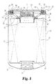
- a fluid filter 20 which includes an outer shell 21, nutplate 22, filter cartridge 23, spring 24, inner elastomeric gasket 25, outer elastomeric gasket 26, and retainer 27.
- Outer shell 21 is a metal, annular member with a closed end 31 and axially opposite thereto an open end 32.
- Nutplate 22 is a unitary metal stamping with an internally-threaded flow outlet 33 and an outer peripheral edge 34. The free edge 35 of outer shell 21 which defines the open end 32 is rolled over and around the outer peripheral edge 34 of the nutplate 22 so as to securely anchor the nutplate to the outer shell 21 at interface 36. This method of assembly creates what would be described as a seamless construction for the connection between the nutplate and outer shell.
- the annular filter cartridge 23 includes a generally cylindrical filtering element 38, a closed endcap 39 which is positioned adjacent to closed end 31 and to spring 24, and an open endcap 40 which is positioned adjacent to the nutplate 22 and inner gasket 25.
- the outer radial flange 41 of the inner gasket is positioned in tight sealing engagement between the annular bend 42 of the nutplate 22 and the upper surface 43 of open endcap 40.
- Fluid filter 20 is constructed and functions in a way typical of earlier filters except for the use of a floating and self-centering retainer 27, the annular outer gasket 26, the rolled over seamless interface 36 between the outer shell and the nutplate and the relationship between the floating retainer 27, gasket 26, and the shell/nutplate interface 36. While these novel components and their novel relationships shall be described in greater detail, the reference to the otherwise typical construction means that the flow paths, in and out, and the filtering function are typical of earlier fluid filters of this general type. Accordingly, the components such as the spring 24, endcaps 39 and 40, inner gasket 25, nutplate 22, and outer shell 21 generally perform in their normal and typical fashion.
- retainer 27 is a unitary annular component which is configured as a hollow ring with an outer, annular and radially-extending flange 47, cylindrical sidewall 48, and an inwardly-directed upper radial lip 49.
- the retainer 27 is a plastic member which can be fabricated as a molded, stamped, or vacuum formed component.
- the inner circular edge 50 of lip 49 defines center opening 51 which is located generally concentric with flow outlet 33 in the final assembly of fluid filter 20.
- Flange 47 is substantially flat and spaced apart from lip 49 by sidewall 48.
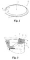
- the upper surface 52 of flange 47 supports outer gasket 26. As is illustrated in FIG.
- the outside diameter dimensional size of flange 47 is smaller than the inside diameter dimensional size of inner surface 53 of the raised cylindrical wall 54 of nutplate 22.
- the smaller diameter size of flange 47 relative to surface 53 allows retainer 27 to float radially on upper surface 58 of nutplate 22 relative to inner surface 53.
- This lateral or radial shifting (i.e., floating) which is permitted due to the shaping and sizing of the retainer relative to the nutplate means that the retainer 27 is self-centering or self-aligning as it assembles with the outer gasket 26 into the nutplate 22 and into the remainder of the fluid filter 20.
- Sidewall 48 which is generally cylindrical and flange 47 in combination with upper surface 58, wall 54, and free edge 35 define an annular receiving channel 59 with a U-shaped lateral cross section for receipt of gasket 26.
- Gasket 26 is sized such that there is a radial compression fit between the gasket and free edge 35 (specifically that portion of the outer shell which is wrapped or rolled over peripheral edge 34 and wall 54 and against surface 53) and between the gasket 26 and sidewall 48.
- the compression forces directed radially inwardly are equally and oppositely balanced with the compression forces directed radially outwardly and this is enabled by the floating, self-centering nature of the retainer 27 relative to the nutplate 22.
- annular gasket 26 is such that when placed in contact against flange 47, an upper annular portion 60 extends axially above lip 49 and above the end surface 61 of outer shell 21.
- the surface of the mounting head pushes axially on the upper annular portion 60 which is then compressed in the direction of flange 47.
- This axial compression creates a sealed interface between gasket 26 and flange 47 and a sealed interface between gasket 26 (particularly portion 60) and the mounting head.
- This axial compression of gasket 26 also increases the degree of radial, side compression between gasket 26 and sidewall 48 and between gasket 26 and the rolled over portion of shell 21 which is in contact with inner surface 53. It will be understood that any possible leakage path from the inferior of the fluid filter 20 to the exterior is sealed by the compression of gasket 26 against any assembly interface which could result in fluid leakage therethrough.
- the outer gasket 26 can have a variety of lateral cross sectional shapes so long as its size and shape results in sufficient side-to-side as well as top-to-bottom compression in order to create the necessary sealed interface (i.e., liquid-tight) against each structural surface which contacts the gasket.
- the retainer 27 continues to be a floating, self-centering member.
- One optional feature of the design of gasket 26 is to shape or configure the gasket in lateral cross section with a plurality of lip extension 64 (see FIG. 3).
- the positioning of each lip extension 64 up against inner surface 53 also positions each lip extension 64 beneath free edge 35 of outer shell 21. Positioning the lip extensions in this manner creates an interlocking fit for the gasket which helps to hold, not only the gasket 26 in position but also the refiner 27, due to the side-to-side compression fit between the gasket 26 and retainer 27.
- the use of the optional lip extension 64 simply adds another means or technique of holding the gasket 26 and retainer 27 in position until the fluid filter 20 is threadedly mounted onto the head.
- the design of the disclosed fluid filer 20 according to the present invention which includes the floating self-centering retainer 27, does not require any increase in the wall thickness of the outer shell material and a thicker or heavier nutplate can be used. In those application requiring greater than a 2MPa (300 psi) burst rating, a thicker nutplate (greater than 4.06mm (0.160 inches) is required so as to reduce the permitted deflection of the nutplate. Thinner nutplates must be used when a capturing groove for the gasket is required to be formed in the nutplate.
- the retainer 27 of the present invention is not welded nor bonded to the nutplate, though the gasket 26 can be molded to the retainer 27 as yet a further option of the present invention.
- the present invention eliminates the dependence on any grooved design in the head and shifts it to the removable retainer 27. Greater flexibility is provided by the present invention since the disclosed design can be used with virtually any mounting head configuration which may be encountered in actual use.
Landscapes
- Chemical & Material Sciences (AREA)
- Chemical Kinetics & Catalysis (AREA)
- Filtration Of Liquid (AREA)
- Lubrication Details And Ventilation Of Internal Combustion Engines (AREA)
- Gasket Seals (AREA)
Claims (5)
- Fluidfilter mit einem umschließenden Mantel; einer in dem umschließenden Mantel angeordneten Filterpatrone; einer Mutterplatte, die in eine Öffnung in dem umschließenden Mantel eingebaut ist; einem Dichtungshalter, der auf der Mutterplatte angeordnet und dadurch gekennzeichnet ist, daß der Dichtungshalter zusammen mit dem umschließenden Mantel einen aufnehmenden Kanal bildet, wobei der Dichtungshalter so ausgebildet und angeordnet ist, daß er seitwärts relativ zu der Mutterplatte bewegbar ist, und eine Dichtung in dem aufnehmenden Kanal angeordnet und so bemessen und geformt ist, daß abgedichtete Schnittstellen zwischen der Dichtung und dem Dichtungshalter und zwischen der Dichtung und dem umschließenden Mantel gebildet werden.
- Fluidfilter nach Anspruch 1, bei dem der Dichtungshalter ein unitäres Teil ist, das so ausgebildet und angeordnet ist, daß es einen ringförmigen Flansch, eine radiale Lippe und eine zylindrische Seitenwand hat, die zwischen dem ringförmigen Flansch und der radialen Lippe angeordnet ist.
- Fluidfilter nach irgendeinem der Ansprüche 1 oder Anspruch 2, bei dem die Mutterplatte ein unitäres Metallstanzteil ist.
- Fluidfilter nach irgendeinem vorhergehenden Anspruch, bei dem der äußere Mantel eine Endfläche hat und die ringförmige Dichtung so ausgebildet und angeordnet ist, daß sie sich axial über diese Endfläche hinaus erstreckt.
- Fluidfilter nach irgendeinem vorhergehenden Anspruch, bei dem die Dichtung ein ringförmiges Elastomerteil ist und eine Lippenverlängerung enthält, die mit dem umschließenden Mantel zusammenwirkt, um dazu beizutragen, die Dichtung in dem aufnehmenden Kanal zu halten.
Applications Claiming Priority (2)
| Application Number | Priority Date | Filing Date | Title |
|---|---|---|---|
| US08/993,285 US6019229A (en) | 1997-12-18 | 1997-12-18 | Self-centering, floating retainer for spin-on filter |
| US993285 | 1997-12-18 |
Publications (2)
| Publication Number | Publication Date |
|---|---|
| EP0933112A1 EP0933112A1 (de) | 1999-08-04 |
| EP0933112B1 true EP0933112B1 (de) | 2005-03-02 |
Family
ID=25539342
Family Applications (1)
| Application Number | Title | Priority Date | Filing Date |
|---|---|---|---|
| EP98310254A Expired - Lifetime EP0933112B1 (de) | 1997-12-18 | 1998-12-15 | Fluidfilter |
Country Status (4)
| Country | Link |
|---|---|
| US (1) | US6019229A (de) |
| EP (1) | EP0933112B1 (de) |
| AU (1) | AU736296B2 (de) |
| DE (1) | DE69829160T2 (de) |
Families Citing this family (27)
| Publication number | Priority date | Publication date | Assignee | Title |
|---|---|---|---|---|
| US6073937A (en) * | 1997-12-03 | 2000-06-13 | Caterpillar Inc. | Composite top plate for a fluid filter and an associated method for forming a composite top plate adapted for attachment to a fluid filter |
| US6202859B1 (en) * | 1999-05-03 | 2001-03-20 | Brian J. Langsdorf | Jseam tapping plate with gasket groove for spin-on filter assemblies |
| US6155431A (en) * | 1999-05-03 | 2000-12-05 | Honeywell International Inc. | Filter assembly |
| US6571961B2 (en) * | 2001-05-03 | 2003-06-03 | Fleetguard, Inc. | Sliding action seam seal and retainer assembly for a fluid filter |
| US20050077231A1 (en) * | 2003-10-14 | 2005-04-14 | Bhardwaj Arun K. | Oil filter gasket with flap |
| US7854433B2 (en) * | 2005-02-24 | 2010-12-21 | Freudenberg-Nok General Partnership | Dynamic seal |
| EP1716902A1 (de) * | 2005-03-04 | 2006-11-02 | Fleetguard Filters PVT. LTD. | Filter |
| EP2340883B1 (de) | 2005-11-15 | 2018-01-10 | Donaldson Company, Inc. | Flüssigkeitsfiltervorrichtungen |
| US8293103B2 (en) * | 2005-12-08 | 2012-10-23 | Donaldson Company, Inc. | Spin-on filter assembly and methods |
| DE202007000747U1 (de) * | 2007-01-12 | 2008-05-21 | Mann+Hummel Gmbh | Wechselfilter |
| US20090001004A1 (en) * | 2007-06-26 | 2009-01-01 | Cummins Filtration Ip, Inc. | Vibration isolation for filtration equipment |
| US8821722B2 (en) * | 2007-06-26 | 2014-09-02 | Cummins Filtration Ip, Inc. | Filter system with vibration dampening |
| DE202007012691U1 (de) * | 2007-09-11 | 2009-02-12 | Mann+Hummel Gmbh | Wechselfilter |
| BRPI0817499A2 (pt) * | 2007-10-02 | 2015-07-14 | Donaldson Co Inc | Cartucho de filtro de líquidos e arranjo de filtro de líquidos |
| US9095795B2 (en) * | 2008-02-27 | 2015-08-04 | Mann+Hummel Purolator Filters Llc | Anti-drainback valve with position positive locking for spin-on oil and fuel filters |
| US8114299B2 (en) * | 2008-02-28 | 2012-02-14 | Cummins Filtration Ip, Inc. | Filter with flow surge protection and method of protecting filter from flow surge |
| DE202008010787U1 (de) * | 2008-08-05 | 2009-12-31 | Mann+Hummel Gmbh | Flüssigkeitsfilter |
| US8900452B2 (en) * | 2008-08-08 | 2014-12-02 | Richard E. Honchen | Self-centering filters, coalescers and separators |
| US9358485B2 (en) | 2011-08-19 | 2016-06-07 | Baldwin Filters, Inc. | Hydraulic spin-on filter cartridge having base plate supporting radially directed seal |
| US9695937B2 (en) | 2014-02-04 | 2017-07-04 | Freudenberg-Nok General Partnership | Energy saving seal with vacuum induced counter-balance and rocking feature |
| US9759330B2 (en) | 2014-02-04 | 2017-09-12 | Freudenberg-Nok General Partnership | Energy saving seal with rocking dust lip |
| US9714710B2 (en) | 2014-02-04 | 2017-07-25 | Freudenberg-Nok General Partnership | Energy saving self-contact seal with pushing bead |
| FR3026959B1 (fr) | 2014-10-13 | 2019-07-12 | Cummins Filtration Ip, Inc. | Filtre amovible pour les cotes d'aspiration et de refoulement dans des systemes de filtration |
| WO2019152305A1 (en) * | 2018-01-31 | 2019-08-08 | Cummins Filtration Ip, Inc. | Systems and methods for securing a sealing member on a filter assembly |
| EP3906108B9 (de) * | 2018-12-31 | 2023-10-25 | Cummins Filtration IP, Inc. | Integriertes multifunktionales endkappendichtungselement |
| IT201900017231A1 (it) * | 2019-09-25 | 2021-03-25 | O M R T S R L | Cartuccia filtrante con flangia di connessione ad un impianto fluidodinamico in battuta contro una sbordatura radiale del contenitore facente parte di detta cartuccia |
| US12611622B2 (en) | 2020-12-18 | 2026-04-28 | Atmus Filtration Inc. | Multistage filter with hydrophobic screen |
Family Cites Families (18)
| Publication number | Priority date | Publication date | Assignee | Title |
|---|---|---|---|---|
| FR1165203A (fr) * | 1956-03-01 | 1958-10-20 | Fram Corp | Filtre à huile |
| US3066803A (en) * | 1958-09-26 | 1962-12-04 | Walker Mfg Co | Filter |
| FR1354823A (fr) * | 1962-10-25 | 1964-03-13 | Joint d'étanchéité | |
| US3282429A (en) * | 1963-12-05 | 1966-11-01 | Gen Motors Corp | Oil filter assembly with replaceable element |
| US3557963A (en) * | 1966-07-21 | 1971-01-26 | Tenneco Inc | Seal for throwaway filter |
| US3589517A (en) * | 1968-12-04 | 1971-06-29 | Sheller Globe Corp | Filter element, relief and check valve, assembly |
| US4345739A (en) * | 1980-08-07 | 1982-08-24 | Barton Valve Company | Flanged sealing ring |
| US4473471A (en) * | 1982-09-13 | 1984-09-25 | Purolator Inc. | Filter sealing gasket with reinforcement ring |
| DE8501736U1 (de) * | 1985-01-24 | 1985-08-22 | Filterwerk Mann & Hummel Gmbh, 7140 Ludwigsburg | Vorrichtung zum Abscheiden von Öltröpfchen aus Luft |
| US4832844A (en) * | 1986-06-05 | 1989-05-23 | Ayers William R | Seal for a spin-on filter |
| GB8624423D0 (en) * | 1986-10-11 | 1986-11-12 | Lucas Ind Plc | Filter assembly |
| JPS63162009A (ja) * | 1986-12-26 | 1988-07-05 | Nippon Denso Co Ltd | カ−トリツジ式オイルフイルタ |
| US4969994A (en) * | 1987-01-16 | 1990-11-13 | Donaldson Company, Inc. | Seal arrangement for fluid filters and method |
| US4992166A (en) * | 1988-06-13 | 1991-02-12 | Facet Enterprises, Inc. | Plastic fluid filter and method for manufacturing same |
| US5180490A (en) * | 1992-01-31 | 1993-01-19 | Baldwin Filters, Inc. | Lubricant filter assembly with internal bypass lock-out |
| US5342511A (en) * | 1993-07-06 | 1994-08-30 | Baldwin Filters, Inc. | Oil filter with inner and outer coaxial filter elements |
| CZ261095A3 (en) * | 1994-10-07 | 1996-04-17 | Sankyo Co | Oxime derivatives, process of their preparation, pharmaceutical composition containing thereof and their use |
| US5525226A (en) * | 1994-10-14 | 1996-06-11 | Baldwin Filters, Inc. | Preformed gasket with retaining tabs |
-
1997
- 1997-12-18 US US08/993,285 patent/US6019229A/en not_active Expired - Lifetime
-
1998
- 1998-12-15 DE DE69829160T patent/DE69829160T2/de not_active Expired - Lifetime
- 1998-12-15 EP EP98310254A patent/EP0933112B1/de not_active Expired - Lifetime
- 1998-12-17 AU AU97157/98A patent/AU736296B2/en not_active Ceased
Also Published As
| Publication number | Publication date |
|---|---|
| DE69829160T2 (de) | 2005-07-21 |
| AU9715798A (en) | 1999-07-08 |
| US6019229A (en) | 2000-02-01 |
| DE69829160D1 (de) | 2005-04-07 |
| EP0933112A1 (de) | 1999-08-04 |
| AU736296B2 (en) | 2001-07-26 |
Similar Documents
| Publication | Publication Date | Title |
|---|---|---|
| EP0933112B1 (de) | Fluidfilter | |
| US5118417A (en) | High-strength disposable tube filter | |
| AU692631B2 (en) | Replaceable spin-on filter with molded, unitary nutplate | |
| EP0341263B1 (de) | Flüssigkeitsfilter | |
| EP0612926B1 (de) | Kugelgelenk mit Staubschutzkappe | |
| US4969994A (en) | Seal arrangement for fluid filters and method | |
| US5116499A (en) | High-strength spin-on tube filter | |
| JPH11244617A (ja) | フィルタおよびスピンオン・フィルタ | |
| US4324660A (en) | Fluid filter | |
| CA2153288A1 (en) | Filter | |
| AU706553B2 (en) | A filter element for a fluid filter | |
| US4400864A (en) | Fluid filter | |
| US5988399A (en) | Spin-on filter | |
| US3490597A (en) | Cover plate for spin-on-filter | |
| GB2110110A (en) | Air filter | |
| US20200078708A1 (en) | J-Hook Filter Assembly | |
| US6571961B2 (en) | Sliding action seam seal and retainer assembly for a fluid filter | |
| US5453195A (en) | High strength filter | |
| WO2000066244A1 (en) | J-shaped seam tapping plate with gasket groove for spin-on filter assemblies | |
| WO2010065179A1 (en) | Anti-rotation of shell relative to nutplate | |
| CA2121517C (en) | Fluid flow filter and method of making same | |
| CA2374872C (en) | Wing tapping plate for spin-on filters | |
| US6230900B1 (en) | Filter assembly and process for producing the same | |
| EP1189669B1 (de) | Filtervorrichtung | |
| JPS6146708B2 (de) |
Legal Events
| Date | Code | Title | Description |
|---|---|---|---|
| PUAI | Public reference made under article 153(3) epc to a published international application that has entered the european phase |
Free format text: ORIGINAL CODE: 0009012 |
|
| AK | Designated contracting states |
Kind code of ref document: A1 Designated state(s): DE FR GB IT |
|
| AX | Request for extension of the european patent |
Free format text: AL;LT;LV;MK;RO;SI |
|
| 17P | Request for examination filed |
Effective date: 19990719 |
|
| AKX | Designation fees paid |
Free format text: AT BE CH CY LI |
|
| REG | Reference to a national code |
Ref country code: DE Ref legal event code: 8566 |
|
| RBV | Designated contracting states (corrected) |
Designated state(s): DE FR GB IT |
|
| 17Q | First examination report despatched |
Effective date: 20030519 |
|
| GRAP | Despatch of communication of intention to grant a patent |
Free format text: ORIGINAL CODE: EPIDOSNIGR1 |
|
| GRAS | Grant fee paid |
Free format text: ORIGINAL CODE: EPIDOSNIGR3 |
|
| GRAA | (expected) grant |
Free format text: ORIGINAL CODE: 0009210 |
|
| AK | Designated contracting states |
Kind code of ref document: B1 Designated state(s): DE FR GB IT |
|
| PG25 | Lapsed in a contracting state [announced via postgrant information from national office to epo] |
Ref country code: IT Free format text: LAPSE BECAUSE OF FAILURE TO SUBMIT A TRANSLATION OF THE DESCRIPTION OR TO PAY THE FEE WITHIN THE PRESCRIBED TIME-LIMIT;WARNING: LAPSES OF ITALIAN PATENTS WITH EFFECTIVE DATE BEFORE 2007 MAY HAVE OCCURRED AT ANY TIME BEFORE 2007. THE CORRECT EFFECTIVE DATE MAY BE DIFFERENT FROM THE ONE RECORDED. Effective date: 20050302 Ref country code: FR Free format text: LAPSE BECAUSE OF NON-PAYMENT OF DUE FEES Effective date: 20050302 |
|
| REG | Reference to a national code |
Ref country code: GB Ref legal event code: FG4D |
|
| RIN1 | Information on inventor provided before grant (corrected) |
Inventor name: RAO, PRABHAKAR B. |
|
| REF | Corresponds to: |
Ref document number: 69829160 Country of ref document: DE Date of ref document: 20050407 Kind code of ref document: P |
|
| PGFP | Annual fee paid to national office [announced via postgrant information from national office to epo] |
Ref country code: GB Payment date: 20051207 Year of fee payment: 8 |
|
| PLBE | No opposition filed within time limit |
Free format text: ORIGINAL CODE: 0009261 |
|
| STAA | Information on the status of an ep patent application or granted ep patent |
Free format text: STATUS: NO OPPOSITION FILED WITHIN TIME LIMIT |
|
| 26N | No opposition filed |
Effective date: 20051205 |
|
| EN | Fr: translation not filed | ||
| GBPC | Gb: european patent ceased through non-payment of renewal fee |
Effective date: 20061215 |
|
| PG25 | Lapsed in a contracting state [announced via postgrant information from national office to epo] |
Ref country code: GB Free format text: LAPSE BECAUSE OF NON-PAYMENT OF DUE FEES Effective date: 20061215 |
|
| REG | Reference to a national code |
Ref country code: DE Ref legal event code: R082 Ref document number: 69829160 Country of ref document: DE Representative=s name: FRIESE GOEDEN PATENTANWAELTE PARTGMBB, DE Ref country code: DE Ref legal event code: R082 Ref document number: 69829160 Country of ref document: DE Representative=s name: FRIESE GOEDEN, DE Ref country code: DE Ref legal event code: R082 Ref document number: 69829160 Country of ref document: DE Representative=s name: ANDRAE WESTENDORP PATENTANWAELTE PARTNERSCHAFT, DE |
|
| REG | Reference to a national code |
Ref country code: DE Ref legal event code: R082 Ref document number: 69829160 Country of ref document: DE Representative=s name: FRIESE GOEDEN PATENTANWAELTE PARTGMBB, DE Ref country code: DE Ref legal event code: R082 Ref document number: 69829160 Country of ref document: DE Representative=s name: FRIESE GOEDEN, DE |
|
| PGFP | Annual fee paid to national office [announced via postgrant information from national office to epo] |
Ref country code: DE Payment date: 20171229 Year of fee payment: 20 |
|
| REG | Reference to a national code |
Ref country code: DE Ref legal event code: R071 Ref document number: 69829160 Country of ref document: DE |