EP0933101B1 - Dispositif de retenue d'une chaussure sur une planche de glisse - Google Patents
Dispositif de retenue d'une chaussure sur une planche de glisse Download PDFInfo
- Publication number
- EP0933101B1 EP0933101B1 EP99100470A EP99100470A EP0933101B1 EP 0933101 B1 EP0933101 B1 EP 0933101B1 EP 99100470 A EP99100470 A EP 99100470A EP 99100470 A EP99100470 A EP 99100470A EP 0933101 B1 EP0933101 B1 EP 0933101B1
- Authority
- EP
- European Patent Office
- Prior art keywords
- cavity
- base
- cushion
- pad
- peripheral edge
- Prior art date
- Legal status (The legal status is an assumption and is not a legal conclusion. Google has not performed a legal analysis and makes no representation as to the accuracy of the status listed.)
- Expired - Lifetime
Links
Images


Classifications
-
- A—HUMAN NECESSITIES
- A63—SPORTS; GAMES; AMUSEMENTS
- A63C—SKATES; SKIS; ROLLER SKATES; DESIGN OR LAYOUT OF COURTS, RINKS OR THE LIKE
- A63C10/00—Snowboard bindings
- A63C10/02—Snowboard bindings characterised by details of the shoe holders
- A63C10/10—Snowboard bindings characterised by details of the shoe holders using parts which are fixed on the shoe, e.g. means to facilitate step-in
- A63C10/103—Snowboard bindings characterised by details of the shoe holders using parts which are fixed on the shoe, e.g. means to facilitate step-in on the sides of the shoe
-
- A—HUMAN NECESSITIES
- A63—SPORTS; GAMES; AMUSEMENTS
- A63C—SKATES; SKIS; ROLLER SKATES; DESIGN OR LAYOUT OF COURTS, RINKS OR THE LIKE
- A63C10/00—Snowboard bindings
- A63C10/28—Snowboard bindings characterised by auxiliary devices or arrangements on the bindings
- A63C10/285—Pads as foot or binding supports, e.g. pads made of foam
-
- A—HUMAN NECESSITIES
- A63—SPORTS; GAMES; AMUSEMENTS
- A63C—SKATES; SKIS; ROLLER SKATES; DESIGN OR LAYOUT OF COURTS, RINKS OR THE LIKE
- A63C10/00—Snowboard bindings
- A63C10/16—Systems for adjusting the direction or position of the bindings
- A63C10/18—Systems for adjusting the direction or position of the bindings about a vertical rotation axis relative to the board
Definitions
- the invention relates to the field of devices for retaining a shoe on a board, and particularly relates to devices used in the practice of surfing on snow, or snowboard.
- Snowboarding is usually done with a board and shoes on the board by restraints.
- Some devices comprise a base, intended to be secured to the board, and means for retaining the boot on the base.
- Cushions housed in cavities of the base so as to contact the sole of the shoe, allow to dampen shocks related to driving the board.
- the structures of cushions and cavities are such that each cushion is held in a cavity by the board when the base is secured to the board. When the base is disengaged from the board, each cushion can be removed from its home cavity.
- Removable cushions make them easy to replace when worn, but assembly, adjustment, or maintenance of the devices.
- This problem is particularly perceptible to people whose job is to rent surfboards to users because these people must frequently manipulate retainers for adjusting and maintaining them.
- the subject of the invention is a retaining device on which at least one cushion can be removably retained without it being difficult or tedious to change it.
- the invention proposes a device for retaining a shoe on a board of slides, the device comprising a base which has an upper face provided for receive the sole of the shoe and a lower face provided to take support on the board, at least one cavity being formed in the thickness of the base between the face upper and lower face to accommodate a cushion, the cushion projecting in part from less compared to the upper face when it is housed in the cavity, a means allowing a detachable attachment of the cushion in the cavity, the means for manipulating the device without losing the cushion.
- the device according to the invention is characterized in that the means comprises a shape projecting from a peripheral edge of the cavity.
- This arrangement makes the change of the cushion easy and quick to perform. In addition, it is also easy to mount, adjust, or maintain the device.
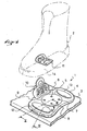
- a retaining device 1, visible in FIG. 1, makes it possible to retain a boot 2 on a board 3.
- the device 1 comprises a base 4 retained on the board 3 by means of retained, well known to those skilled in the art, represented in the form of a disc 5 and screws 6, 7, 8, 9. Plate 3 is shown in part only for convenience.
- a retaining means 10 is secured to the base 4 to hold the shoe 2 on the base 4.
- the retaining means 10 is shown in the form of a structure which allows a removable attachment of an anchoring means 11, itself secured to the shoe 2 by any suitable means.
- the retaining means 10 and the shoe 2 associated with the anchoring means 11 are known by the document FR 96 13158 and will not be described in more detail here.
- the device 1 has front and rear cushions 12 and 13 intended to contact the sole 14 of the shoe 2 when the latter is retained on the base 4.
- the cushions 12, 13 are retained on the base 4 removably as it is better understand using Figures 2, 3 and 4.
- FIG. 2 shows that the cushion 12 can be introduced into a cavity 15 of the base 4, to be retained in the cavity 15.
- the cushion 12 has the shape of a plate which has an upper face 16 provided to contact the base 4, and a face lower 17 provided to contact the board 3.
- a boss 18 protrudes on the upper face 16 of the plate, the boss 18 having a contact face 19 provided to contact the shoe 2, and an edge device 20 connecting the contact face 19 to the upper face 16.
- the cavity 15 passes through the thickness t of the base 4, the cavity 15 having a portion upper 21 which accommodates the boss 18 of the cushion 12, and a lower portion 22 which welcomes the cushion plate 12.
- the upper portion 21 of the cavity 15 has a peripheral edge 23 whose length is substantially equal to the length of the peripheral edge 20 of the boss 18 of the cushion 12.
- the cushion 12 can be introduced into the cavity 15 on the side of a lower face 24 of the base 4, the face 24 being provided to bear on the board 3. Portions 25, 26, 27, 28, 29, 30 of the plate, delimiting the upper face 16, prevent any displacement cushion 12 in a direction from the lower face 24 to an upper face 31 of the base 4.
- a displacement of the cushion 12 relative to the base 4, in any direction substantially parallel to the upper face 31, is prevented by contact with the peripheral edge 20 on the peripheral edge 23.
- Fastening means oppose a displacement of the cushion 12 with respect to the base 4 in a direction from the upper face 31 to the lower face 24, that is to say in a direction of separation of the cushion 12 with respect to the base 4.
- attachment means are represented in the form of bosses protruding by relative to the peripheral edge 23 of the upper portion 21 of the cavity 15, such as the bosses 32, 33.
- bosses 33 and 34 of the edge 23 are lodged respectively in notches 35, 36 for receiving the bosses 33, 34, the notches 35, 36 being formed in the peripheral edge 20 of the cushion 12.
- the base 4 is made of a relatively rigid material, that is to say a material which deforms very little under the action of forces exerted by a user during the course of driving of plate 3.
- a metal alloy or a reinforced plastic material or not, as a polyamide reinforced with glass fibers, is very suitable.
- the cushions 12, 13 are made of a relatively flexible material, that is to say a material that can become deformed when manual pressure is exerted on it and its initial shape when the pressure disappears.
- the cushion 12 is fitted to the hand in the cavity 15 when the device 1 is not retained on the board 3.
- the separation of the cushion 12 and the base 4 is easily done when the device 1 is not retained on the board 3. Just push the boss 18 by hand so as to remove the upper face 16 of the cushion 12 of the base 4. This operation is easily done thanks to the flexibility of the material constituting the cushion 12.
- the flexibility of the cushion 12 is increased by the presence of a cavity 37 of the cushion 12 which opens on the lower face 17.
- the advantage is that the replacement of the cushion 12 is very easy and very fast.
- the cushion 12 can not out of the cavity 15 when the device 1 is retained on the board 3.
- the cushion 12 can damping shocks of the shoe 2 on the base 4.
- the number of bosses of the peripheral edge 23 is not limited.
- the bosses of the edge 23 may have any suitable shape, such as that of a prism, a portion of sphere, a cylinder, a cone or other.
- the bosses could be arranged on the peripheral edge 20 of the cushion 12.
- Notches such as notches 35, 36 are not essential.
- the presence of the cavity 37 is not essential.
- the plate delimiting the upper face 16 and the lower face 17 could have a continuous appearance, that is to say with material joining the portions 25, 26, 27, 28, 29, 30.
- Each cushion 12, 13 may have an appropriate shape such as that of an ellipse, a circle, a polygon or other.
- the cavity 15 could be non-through and the mounting of the cushion could be done side of the upper face 31.
- the means for detachable attachment of the cushion 12 may have a structure different from that using bosses.
- nails could cross the cushion 12 between the faces 16 and 17 to be planted in the base 4.
- the head of the nails is facing the board 3.
- the flexibility of the cushion 12 allows it to deform to let the heads of the nails into the material constituting the cushion 12. From more, the nails and the base 4 can be monobloc.
- the device comprises a cushion 40 and a base 41.
- the cushion 40 has two bosses 42, 43 intended to be housed respectively in two cavities 44, 45 of the base 41.
- a retaining means 46 and a disc 47 serve respectively to retain a shoe on the base 41 and retain the base 41 on a board.
- the cushion 40 has an orifice 48 which allows the disc 47 to cooperate with the board for holding the base 41.
- the cushion 40 has an upper face 49 on which the base 41 is supported. when the latter is retained on the board. That is to say that when the device is retained on the board, the base 41 is not in contact with the board, because the base 41 takes support on the cushion 40.
- bosses 42, 43 are protruded by relative to an upper face 51 of the base 41. This allows the bosses 42, 43 to contact the sole of the shoe to cushion shocks or vibrations of the shoe compared to the device. It could be provided, in an alternative embodiment, a number of bosses greater than two to contact the sole of the shoe.
- Each of the peripheral edges 52, 53 of the cavities 44, 45 has means latches shown in the form of bosses 54, 55, 56 and 57.
Landscapes
- Footwear And Its Accessory, Manufacturing Method And Apparatuses (AREA)
- Suspension Of Electric Lines Or Cables (AREA)
- Bridges Or Land Bridges (AREA)
- Materials Applied To Surfaces To Minimize Adherence Of Mist Or Water (AREA)
Description
- la figure 1 est une vue en perspective d'un dispositif selon l'invention,
- la figure 2 est une vue en perspective éclatée d'une partie du dispositif,
- la figure 3 est une coupe selon III-III de la figure 1,
- la figure 4 est une coupe selon IV-IV de la figure 1,
- la figure 5 est une vue en perspective éclatée d'un dispositif selon une variante de réalisation de l'invention.
Claims (8)
- Dispositif de retenue (1) d'une chaussure (2) sur une planche de glisse (3), le dispositif (1) comprenant une embase (4) qui présente une face supérieure (31) prévue pour accueillir la semelle (14) de la chaussure (2) et une face inférieure (24) prévue pour prendre appui sur la planche (3), au moins une cavité (15) étant ménagée dans l'épaisseur (t) de l'embase (4) entre la face supérieure (31) et la face inférieure (24) pour loger un coussin (12), le coussin (12) faisant saillie en partie au moins par rapport à la face supérieure (31) quand il est logé dans la cavité (15), un moyen permettant un accrochage amovible du coussin (12) dans la cavité (15), le moyen permettant de manipuler le dispositif (1) sans perdre le coussin (12), caractérisé par le fait que le moyen comprend une forme en saillie par rapport à un bord périphérique (23) de la cavité (15).
- Dispositif (1) selon la revendication 1, caractérisé par le fait que le coussin (12) a la forme d'une plaque qui présente une face supérieure (16) prévue pour contacter embase (4) et une face inférieure (17) prévue pour contacter la planche (3), au moins un bossage (18) formant saillie sur la face supérieure (16) de la plaque, le bossage (18) présentant une face de contact (19) prévue pour contacter la chaussure (2), et un bord périphérique (20) reliant la face de contact (19) à la face supérieure (16).
- Dispositif (1) selon la revendication 2, caractérisé par le fait que la cavité (15) traverse l'épaisseur (t) de l'embase (4), la cavité (15) présentant une portion supérieure (21) prévue pour accueillir le bossage (18) du coussin (12), et une portion inférieure (22) prévue pour accueillir la plaque du coussin (12), la portion supérieure (21) de la cavité (15) présentant un bord périphérique (23) dont la longueur est sensiblement égale à la longueur du bord périphérique (20) du bossage (18) du coussin (12).
- Dispositif (1) selon la revendication 3, caractérisé par le fait que le moyen d'accrochage comprend au moins un bossage (33, 34) en saillie par rapport au bord périphérique (23) de la portion supérieure (21) de la cavité (15).
- Dispositif (1) selon l'une quelconque des revendications 2 à 4, caractérisé par le fait que le coussin (12) présente une cavité (37) qui débouche sur la face inférieure (24).
- Dispositif (1) selon la revendication 4 ou 5, caractérisé par le fait que le bord périphérique (20) du coussin (12), qui relie la face de contact (19) à la face supérieure (16), présente au moins une encoche (35, 36) de réception du bossage (33, 34) du bord périphérique (23) de la portion supérieure (21) de la cavité (15).
- Dispositif (1) selon l'une quelconque des revendications 1 à 6, caractérisé par le fait que l'embase (4) est réalisée avec un matériau relativement rigide, et que le coussin (12, 13) est réalisé avec un matériau relativement souple.
- Dispositif selon l'une quelconque des revendications 1 à 7, caractérisé par le fait que la face inférieure de l'embase (41) est prévue pour prendre appui sur le coussin (40).
Applications Claiming Priority (2)
| Application Number | Priority Date | Filing Date | Title |
|---|---|---|---|
| FR9801265 | 1998-01-30 | ||
| FR9801265A FR2774303B1 (fr) | 1998-01-30 | 1998-01-30 | Dispositif de retenue d'une chaussure sur une planche de glisse |
Publications (2)
| Publication Number | Publication Date |
|---|---|
| EP0933101A1 EP0933101A1 (fr) | 1999-08-04 |
| EP0933101B1 true EP0933101B1 (fr) | 2005-10-12 |
Family
ID=9522562
Family Applications (1)
| Application Number | Title | Priority Date | Filing Date |
|---|---|---|---|
| EP99100470A Expired - Lifetime EP0933101B1 (fr) | 1998-01-30 | 1999-01-12 | Dispositif de retenue d'une chaussure sur une planche de glisse |
Country Status (5)
| Country | Link |
|---|---|
| US (1) | US6247709B1 (fr) |
| EP (1) | EP0933101B1 (fr) |
| AT (1) | ATE306300T1 (fr) |
| DE (1) | DE69927627T2 (fr) |
| FR (1) | FR2774303B1 (fr) |
Families Citing this family (14)
| Publication number | Priority date | Publication date | Assignee | Title |
|---|---|---|---|---|
| FR2769236B1 (fr) * | 1997-10-03 | 2000-02-04 | Salomon Sa | Cale d'amortissement pour dispositif de retenue d'une chaussure sur une planche de glisse destinee a la pratique du surf sur neige, et dispositif muni d'une telle cale |
| US6782115B2 (en) * | 1998-04-16 | 2004-08-24 | Digimarc Corporation | Watermark holograms |
| US6733030B2 (en) * | 2001-04-18 | 2004-05-11 | Shimano, Inc. | Snowboard binding system |
| US6536795B2 (en) * | 2001-04-18 | 2003-03-25 | Shimano Inc. | Snowboard binding system |
| US20040145155A1 (en) * | 2003-01-24 | 2004-07-29 | Dakuga Holding Ltd. | Spacer for snowboard |
| FR2862545B1 (fr) * | 2003-11-24 | 2007-11-23 | Salomon Sa | Dispositif d'accueil d'un pied ou d'une chaussure |
| ITMI20050091A1 (it) * | 2005-01-24 | 2006-07-25 | Core S R L | Attacco per la connessione di una calzatura ad una tavola da neve e simili |
| EP2038022B1 (fr) * | 2006-07-07 | 2009-12-23 | The Burton Corporation | Assise plantaire pour fixation de planche de glisse |
| US20090256334A1 (en) * | 2008-04-14 | 2009-10-15 | Lynn Handel | Temporary snowboard fastener |
| IT1400976B1 (it) * | 2010-07-01 | 2013-07-05 | Core S R L | Attacco per la connessione di una calzatura ad una tavola da neve. |
| ES1074122Y (es) * | 2010-10-22 | 2011-06-24 | Huerta Almansa Asier De | Fijacion giratoria para snowboard |
| US10179272B2 (en) | 2014-11-14 | 2019-01-15 | The Burton Corporation | Snowboard binding and boot |
| US9220970B1 (en) | 2014-11-14 | 2015-12-29 | The Burton Corporation | Snowboard binding and boot |
| US9149711B1 (en) | 2014-11-14 | 2015-10-06 | The Burton Corporation | Snowboard binding and boot |
Family Cites Families (10)
| Publication number | Priority date | Publication date | Assignee | Title |
|---|---|---|---|---|
| DE1917425A1 (de) * | 1969-04-03 | 1970-10-15 | Hannes Marker | Sicherheits-Skibindung |
| US3578349A (en) * | 1969-05-26 | 1971-05-11 | James Mitchell Edmund | Safety ski binding |
| AT327071B (de) * | 1974-02-20 | 1976-01-12 | Smolka & Co Wiener Metall | Gleitplatte fur skibindungen |
| FR2708868B1 (fr) * | 1993-08-13 | 1995-09-29 | Salomon Sa | Dispositif d'appui d'une chaussure sur un ski. |
| US5404614A (en) * | 1994-01-06 | 1995-04-11 | Royal Appliance Mfg. Co. | Latch assembly for blower of wet/dry vacuum cleaner |
| US5503900A (en) * | 1994-08-30 | 1996-04-02 | Herbert E. Fletcher | Snowboard padding |
| ATE207774T1 (de) * | 1995-08-02 | 2001-11-15 | Marker Deutschland Gmbh | Bindung-schuh-kombination für snowboards oder dgl. |
| FR2741544B1 (fr) * | 1995-11-29 | 1997-12-19 | Rossignol Sa | Ski equipe d'un dispositif destine a adapter la position transversale d'une fixation en fonction des impulsions du skieur |
| US5909894A (en) * | 1997-01-02 | 1999-06-08 | K-2 Corporation | Snowboard binding |
| FR2763252B1 (fr) * | 1997-05-13 | 1999-07-23 | Look Fixations Sa | Plaque d'appui pour fixation de securite |
-
1998
- 1998-01-30 FR FR9801265A patent/FR2774303B1/fr not_active Expired - Fee Related
-
1999
- 1999-01-12 DE DE69927627T patent/DE69927627T2/de not_active Expired - Lifetime
- 1999-01-12 EP EP99100470A patent/EP0933101B1/fr not_active Expired - Lifetime
- 1999-01-12 AT AT99100470T patent/ATE306300T1/de not_active IP Right Cessation
- 1999-01-28 US US09/238,581 patent/US6247709B1/en not_active Expired - Fee Related
Also Published As
| Publication number | Publication date |
|---|---|
| US6247709B1 (en) | 2001-06-19 |
| FR2774303A1 (fr) | 1999-08-06 |
| EP0933101A1 (fr) | 1999-08-04 |
| DE69927627T2 (de) | 2006-06-22 |
| DE69927627D1 (de) | 2005-11-17 |
| FR2774303B1 (fr) | 2000-04-28 |
| ATE306300T1 (de) | 2005-10-15 |
Similar Documents
| Publication | Publication Date | Title |
|---|---|---|
| EP0933101B1 (fr) | Dispositif de retenue d'une chaussure sur une planche de glisse | |
| EP0278281B1 (fr) | Chaussure de ski | |
| EP0895727B1 (fr) | Chaussure de sport à flexibilité déterminée | |
| EP0933100B1 (fr) | Dispositif de retenue d'une chaussure sur une planche de glisse | |
| EP1108450B1 (fr) | Dispositif de retenue d'une chaussure sur une planche de glisse | |
| EP0825892B1 (fr) | Dispositif de retenue d'une chaussure sur une planche de glisse | |
| WO1991008808A1 (fr) | Fixation de securite de ski alpin | |
| EP0804949A1 (fr) | Dipositif de retenue d'une chaussure sur une planche de glisse destinée à la pratique du surf | |
| EP0634197B1 (fr) | Elément de fixation de ski alpin | |
| EP3747751B1 (fr) | Pédale automatique pour cycle | |
| FR2793156A1 (fr) | Dispositif de retenue d'une chaussure sur une planche de glisse | |
| FR2817163A1 (fr) | Ensemble de retenue d'une chaussure sur une planche | |
| EP0634196B1 (fr) | Elément de fixation de ski alpin | |
| EP1508352A1 (fr) | Fixation de surf des neiges | |
| EP0623370A1 (fr) | Dispositif interface entre un ski et des éléments de fixation | |
| EP0752258A1 (fr) | Dispositif de retenue d'une chaussure sur une planche de glisse | |
| FR2800623A1 (fr) | Dispositif interface entre un ski et des elements de retenue d'une chaussure sur le ski et ski ainsi equipe | |
| FR2769239A1 (fr) | Dispositif de retenue d'une chaussure sur une planche de glisse destinee a la pratique du surf sur neige | |
| EP0700699B1 (fr) | Fixation de ski | |
| FR2757411A1 (fr) | Dispositif de retenue d'une chaussure sur une planche de glisse destinee a la pratique du surf sur neige | |
| EP0804950A1 (fr) | Dipositif de retenue d'une chaussure sur une planche de glisse destinée à la pratique du surf | |
| FR2810893A1 (fr) | Dispositif interface entre un ski alpin et des elements de retenue de la chaussure sur le ski | |
| FR2796852A1 (fr) | Dispositif interface entre une chaussure et un ski | |
| FR2668941A1 (fr) | Fixation de securite de ski alpin. | |
| FR2810253A1 (fr) | Raquette a neige |
Legal Events
| Date | Code | Title | Description |
|---|---|---|---|
| PUAI | Public reference made under article 153(3) epc to a published international application that has entered the european phase |
Free format text: ORIGINAL CODE: 0009012 |
|
| AK | Designated contracting states |
Kind code of ref document: A1 Designated state(s): AT CH DE FR LI |
|
| AX | Request for extension of the european patent |
Free format text: AL;LT;LV;MK;RO;SI |
|
| 17P | Request for examination filed |
Effective date: 20000201 |
|
| AKX | Designation fees paid |
Free format text: AT CH DE FR LI |
|
| 17Q | First examination report despatched |
Effective date: 20031009 |
|
| GRAP | Despatch of communication of intention to grant a patent |
Free format text: ORIGINAL CODE: EPIDOSNIGR1 |
|
| GRAS | Grant fee paid |
Free format text: ORIGINAL CODE: EPIDOSNIGR3 |
|
| GRAA | (expected) grant |
Free format text: ORIGINAL CODE: 0009210 |
|
| AK | Designated contracting states |
Kind code of ref document: B1 Designated state(s): AT CH DE FR LI |
|
| REG | Reference to a national code |
Ref country code: CH Ref legal event code: EP |
|
| REF | Corresponds to: |
Ref document number: 69927627 Country of ref document: DE Date of ref document: 20051117 Kind code of ref document: P |
|
| PGFP | Annual fee paid to national office [announced via postgrant information from national office to epo] |
Ref country code: FR Payment date: 20060110 Year of fee payment: 8 |
|
| PGFP | Annual fee paid to national office [announced via postgrant information from national office to epo] |
Ref country code: AT Payment date: 20060111 Year of fee payment: 8 |
|
| PGFP | Annual fee paid to national office [announced via postgrant information from national office to epo] |
Ref country code: CH Payment date: 20060113 Year of fee payment: 8 |
|
| PLBE | No opposition filed within time limit |
Free format text: ORIGINAL CODE: 0009261 |
|
| STAA | Information on the status of an ep patent application or granted ep patent |
Free format text: STATUS: NO OPPOSITION FILED WITHIN TIME LIMIT |
|
| 26N | No opposition filed |
Effective date: 20060713 |
|
| PG25 | Lapsed in a contracting state [announced via postgrant information from national office to epo] |
Ref country code: LI Free format text: LAPSE BECAUSE OF NON-PAYMENT OF DUE FEES Effective date: 20070131 Ref country code: CH Free format text: LAPSE BECAUSE OF NON-PAYMENT OF DUE FEES Effective date: 20070131 |
|
| REG | Reference to a national code |
Ref country code: CH Ref legal event code: PL |
|
| REG | Reference to a national code |
Ref country code: FR Ref legal event code: ST Effective date: 20070930 |
|
| PG25 | Lapsed in a contracting state [announced via postgrant information from national office to epo] |
Ref country code: AT Free format text: LAPSE BECAUSE OF NON-PAYMENT OF DUE FEES Effective date: 20070112 |
|
| PG25 | Lapsed in a contracting state [announced via postgrant information from national office to epo] |
Ref country code: FR Free format text: LAPSE BECAUSE OF NON-PAYMENT OF DUE FEES Effective date: 20070131 |
|
| PGFP | Annual fee paid to national office [announced via postgrant information from national office to epo] |
Ref country code: DE Payment date: 20110105 Year of fee payment: 13 |
|
| PG25 | Lapsed in a contracting state [announced via postgrant information from national office to epo] |
Ref country code: DE Free format text: LAPSE BECAUSE OF NON-PAYMENT OF DUE FEES Effective date: 20120801 |
|
| REG | Reference to a national code |
Ref country code: DE Ref legal event code: R119 Ref document number: 69927627 Country of ref document: DE Effective date: 20120801 |