EP0932733B1 - Selbsttragendes bauelement aus expandiertem plastik, insbesondere für die herstellung von bodenplatten und gebäudewänden im allgemeinen - Google Patents
Selbsttragendes bauelement aus expandiertem plastik, insbesondere für die herstellung von bodenplatten und gebäudewänden im allgemeinen Download PDFInfo
- Publication number
- EP0932733B1 EP0932733B1 EP97945836A EP97945836A EP0932733B1 EP 0932733 B1 EP0932733 B1 EP 0932733B1 EP 97945836 A EP97945836 A EP 97945836A EP 97945836 A EP97945836 A EP 97945836A EP 0932733 B1 EP0932733 B1 EP 0932733B1
- Authority
- EP
- European Patent Office
- Prior art keywords
- reinforcing section
- section bar
- sheet
- construction element
- supporting
- Prior art date
- Legal status (The legal status is an assumption and is not a legal conclusion. Google has not performed a legal analysis and makes no representation as to the accuracy of the status listed.)
- Expired - Lifetime
Links
- 238000010276 construction Methods 0.000 title claims abstract description 114
- 239000004033 plastic Substances 0.000 title claims abstract description 78
- 229920003023 plastic Polymers 0.000 title claims abstract description 78
- 238000004519 manufacturing process Methods 0.000 title claims abstract description 8
- 230000003014 reinforcing effect Effects 0.000 claims abstract description 110
- 239000000463 material Substances 0.000 claims abstract description 29
- 238000000465 moulding Methods 0.000 claims description 21
- 238000000034 method Methods 0.000 claims description 12
- 239000004567 concrete Substances 0.000 claims description 11
- 239000004568 cement Substances 0.000 claims description 10
- 239000011505 plaster Substances 0.000 claims description 9
- 238000007669 thermal treatment Methods 0.000 claims description 9
- 239000008187 granular material Substances 0.000 claims description 8
- 229910052602 gypsum Inorganic materials 0.000 claims description 6
- 239000010440 gypsum Substances 0.000 claims description 6
- 238000005266 casting Methods 0.000 claims description 5
- 230000013011 mating Effects 0.000 claims description 5
- 239000011087 paperboard Substances 0.000 claims description 5
- 230000002093 peripheral effect Effects 0.000 claims description 5
- 239000002023 wood Substances 0.000 claims description 5
- 239000000835 fiber Substances 0.000 claims description 4
- 238000007790 scraping Methods 0.000 claims description 4
- 238000003466 welding Methods 0.000 claims description 2
- 239000010410 layer Substances 0.000 description 19
- 239000002184 metal Substances 0.000 description 6
- 229910052751 metal Inorganic materials 0.000 description 6
- 238000004873 anchoring Methods 0.000 description 3
- 230000006835 compression Effects 0.000 description 3
- 238000007906 compression Methods 0.000 description 3
- 239000004794 expanded polystyrene Substances 0.000 description 3
- 238000000926 separation method Methods 0.000 description 3
- 230000032683 aging Effects 0.000 description 2
- 238000005452 bending Methods 0.000 description 2
- 238000005520 cutting process Methods 0.000 description 2
- 230000009977 dual effect Effects 0.000 description 2
- 238000009434 installation Methods 0.000 description 2
- 230000010354 integration Effects 0.000 description 2
- 238000012986 modification Methods 0.000 description 2
- 230000004048 modification Effects 0.000 description 2
- 238000005192 partition Methods 0.000 description 2
- 238000004080 punching Methods 0.000 description 2
- 230000003068 static effect Effects 0.000 description 2
- 239000011800 void material Substances 0.000 description 2
- 235000008733 Citrus aurantifolia Nutrition 0.000 description 1
- 229910001335 Galvanized steel Inorganic materials 0.000 description 1
- 235000011941 Tilia x europaea Nutrition 0.000 description 1
- HCHKCACWOHOZIP-UHFFFAOYSA-N Zinc Chemical compound [Zn] HCHKCACWOHOZIP-UHFFFAOYSA-N 0.000 description 1
- 230000015572 biosynthetic process Effects 0.000 description 1
- 239000011247 coating layer Substances 0.000 description 1
- 230000000052 comparative effect Effects 0.000 description 1
- 239000002131 composite material Substances 0.000 description 1
- 239000004035 construction material Substances 0.000 description 1
- 238000005260 corrosion Methods 0.000 description 1
- 230000007797 corrosion Effects 0.000 description 1
- 230000008878 coupling Effects 0.000 description 1
- 238000010168 coupling process Methods 0.000 description 1
- 238000005859 coupling reaction Methods 0.000 description 1
- 230000000694 effects Effects 0.000 description 1
- 230000002708 enhancing effect Effects 0.000 description 1
- 230000009970 fire resistant effect Effects 0.000 description 1
- 239000003517 fume Substances 0.000 description 1
- 239000008397 galvanized steel Substances 0.000 description 1
- 238000010348 incorporation Methods 0.000 description 1
- 238000009413 insulation Methods 0.000 description 1
- 238000005304 joining Methods 0.000 description 1
- 239000004571 lime Substances 0.000 description 1
- 230000002028 premature Effects 0.000 description 1
- 230000008569 process Effects 0.000 description 1
- 239000012783 reinforcing fiber Substances 0.000 description 1
- 238000007493 shaping process Methods 0.000 description 1
- 239000000126 substance Substances 0.000 description 1
- -1 vapors Substances 0.000 description 1
- 229910052725 zinc Inorganic materials 0.000 description 1
- 239000011701 zinc Substances 0.000 description 1
Images


Classifications
-
- E—FIXED CONSTRUCTIONS
- E04—BUILDING
- E04B—GENERAL BUILDING CONSTRUCTIONS; WALLS, e.g. PARTITIONS; ROOFS; FLOORS; CEILINGS; INSULATION OR OTHER PROTECTION OF BUILDINGS
- E04B5/00—Floors; Floor construction with regard to insulation; Connections specially adapted therefor
- E04B5/16—Load-carrying floor structures wholly or partly cast or similarly formed in situ
- E04B5/17—Floor structures partly formed in situ
- E04B5/18—Floor structures partly formed in situ with stiffening ribs or other beam-like formations wholly cast between filling members
- E04B5/19—Floor structures partly formed in situ with stiffening ribs or other beam-like formations wholly cast between filling members the filling members acting as self-supporting permanent forms
-
- B—PERFORMING OPERATIONS; TRANSPORTING
- B29—WORKING OF PLASTICS; WORKING OF SUBSTANCES IN A PLASTIC STATE IN GENERAL
- B29C—SHAPING OR JOINING OF PLASTICS; SHAPING OF MATERIAL IN A PLASTIC STATE, NOT OTHERWISE PROVIDED FOR; AFTER-TREATMENT OF THE SHAPED PRODUCTS, e.g. REPAIRING
- B29C45/00—Injection moulding, i.e. forcing the required volume of moulding material through a nozzle into a closed mould; Apparatus therefor
- B29C45/14—Injection moulding, i.e. forcing the required volume of moulding material through a nozzle into a closed mould; Apparatus therefor incorporating preformed parts or layers, e.g. injection moulding around inserts or for coating articles
- B29C45/14311—Injection moulding, i.e. forcing the required volume of moulding material through a nozzle into a closed mould; Apparatus therefor incorporating preformed parts or layers, e.g. injection moulding around inserts or for coating articles using means for bonding the coating to the articles
-
- E—FIXED CONSTRUCTIONS
- E04—BUILDING
- E04B—GENERAL BUILDING CONSTRUCTIONS; WALLS, e.g. PARTITIONS; ROOFS; FLOORS; CEILINGS; INSULATION OR OTHER PROTECTION OF BUILDINGS
- E04B5/00—Floors; Floor construction with regard to insulation; Connections specially adapted therefor
- E04B5/02—Load-carrying floor structures formed substantially of prefabricated units
- E04B5/026—Load-carrying floor structures formed substantially of prefabricated units with beams or slabs of plastic
-
- E—FIXED CONSTRUCTIONS
- E04—BUILDING
- E04B—GENERAL BUILDING CONSTRUCTIONS; WALLS, e.g. PARTITIONS; ROOFS; FLOORS; CEILINGS; INSULATION OR OTHER PROTECTION OF BUILDINGS
- E04B5/00—Floors; Floor construction with regard to insulation; Connections specially adapted therefor
- E04B5/16—Load-carrying floor structures wholly or partly cast or similarly formed in situ
- E04B5/32—Floor structures wholly cast in situ with or without form units or reinforcements
- E04B5/36—Floor structures wholly cast in situ with or without form units or reinforcements with form units as part of the floor
- E04B5/38—Floor structures wholly cast in situ with or without form units or reinforcements with form units as part of the floor with slab-shaped form units acting simultaneously as reinforcement; Form slabs with reinforcements extending laterally outside the element
-
- B—PERFORMING OPERATIONS; TRANSPORTING
- B29—WORKING OF PLASTICS; WORKING OF SUBSTANCES IN A PLASTIC STATE IN GENERAL
- B29L—INDEXING SCHEME ASSOCIATED WITH SUBCLASS B29C, RELATING TO PARTICULAR ARTICLES
- B29L2031/00—Other particular articles
- B29L2031/30—Vehicles, e.g. ships or aircraft, or body parts thereof
- B29L2031/3002—Superstructures characterized by combining metal and plastics, i.e. hybrid parts
Definitions
- This invention relates, in a general aspect thereof, to a self-supporting construction element of expanded plastics material, in particular for manufacturing floor elements and walls of buildings in general.
- the present invention relates to a self-supporting construction element comprising:
- self-supporting construction element of expanded plastics will be used to indicate a section member made of an expanded plastics material, such as expanded polystyrene, which possesses mechanical properties adapted to withstand without structural yielding all the strains applied thereon during its transportation and installation.
- European Patent EP 0 459 924 discloses a self-supporting construction element made of expanded plastics material, specifically a floor element, which comprises a substantially parallelepipedic central body in which a reinforcing section bar, made of a thin metal sheet shaped as an I-beam, is integrated during the molding step.
- This inadequate resistance to fire is essentially related to the fact that construction elements made of expanded plastics show an insufficient capability to securely hold outer covering layers, such as the plaster layers used for the outer surface finish.
- an undesirable separation of the outer covering layers may be caused in some instances by a premature "aging" of the plastics surface to which these coverings adhere, a separation which may be further fostered by exposure to heat sources, dusts, fumes, vapors, or chemical substances coming from a source close to the construction elements.
- the technical problem underlying the present invention is, therefore, that of providing a self-supporting construction element made of expanded plastics, which allows to overcome the drawbacks mentioned hereinabove with respect to the cited prior art.
- a construction element of the type indicated above which is characterized in that it further comprises a lath for supporting at least one layer of a suitable covering material, said lath being associated to a fin of said reinforcing section bar lying flush with and substantially parallel to at least one of the faces of said construction element.
- lath for supporting at least one covering layer encompass not only conventional mesh -- either smooth or provided with protruding ribs -- obtained by stretching a suitably notched metal sheet, but also any sheet-like member adapted to support a suitable covering material.
- the construction element of the invention may achieve at one time both adequate self-supporting features, as conferred thereon by the reinforcing section bar integrated within the mass of expanded plastics, and adequate fire-resisting properties thanks to the presence of the lath, which is securely held by the same reinforcing section bar.
- This lath in fact, is capable of supporting a covering layer constituted by a suitable construction material even in case of shrinking of the mass of plastics.
- the lath comprises one or more portions extending flush on opposite lateral sides of the construction element, which may be embedded in and anchored also to the concrete used for incorporating and/or joining together one or more adjacent construction elements.
- a lath thus held securely in place by the reinforcing section bar and/or by the concrete is able to effectively prevent any detachment of the covering layer, even in the presence of the aforementioned aging phenomena of the outer surface of the expanded plastics.
- the material of the covering layer associated to the lath is preferably selected from plaster, cement, or any other fire-retarding or fire-resistant material, such as composites of cement and reinforcing fibers of an appropriate nature.
- the reinforcing section bar is constituted by a material having suitable structural properties, such as cold rolled, preferably zinc-galvanized steel, shaped so as to be provided at one end with at least one fin perpendicularly extending from the central portion thereof.
- the reinforcing section bar is preferably worked to a C, Z or H cross-sectional shape.
- the reinforcing section bar is longitudinally extending within the central body of the construction element along substantially the entire length thereof and is provided with a pair of fins perpendicularly extending from opposite sides of a central portion.
- the fin which extends flush with the construction element serves the function of providing an adequate supporting surface onto which the lath may be secured, while the opposite fin advantageously carries out the function of improving the compression strength of the reinforcing section bar, thereby enhancing the self-supporting properties of the construction element.
- this second fin comprises a first rectilinear portion, substantially perpendicular to the central portion of the reinforcing section bar, and an end portion bent toward the central portion and forming with the first portion of the fin an angle ( ⁇ ) ranging from 40° to 60° and, still more preferably, equal to about 45°.
- Portions of predetermined length of this reinforcing section bar may be obtained by means of conventional bending and cutting operations, known per se, starting from a metal sheet having a height of from 150 to 250 mm and a thickness of from 0.4 to 1.2 mm and, still more preferably, of from 0.5 to 0.8 mm.
- the central portion of the reinforcing section bar will have, after bending, a height of from 100 to 200 mm, while the fin or opposite fins of the section bar will have a width of from 15 to 30 mm.
- the fin which will become fully embedded within the expanded plastics material will have an overall width comprised between 18 and 22 mm.
- the first substantially rectilinear portion of said fin, lying perpendicularly to the central portion of the reinforcing section bar, preferably has a width of from 12 to 18 mm, while the remaining end portion thereof is bent towards the reinforcing section bar to form an angle of about 45°.
- the reinforcing section bar is advantageously provided with a plurality of openings formed in its central portion outside of or included between said fins.
- openings serve the dual advantageous function of lightening the reinforcing section bar thus improving the self-supporting properties of the construction element, and of enabling a better integration of the reinforcing section bar into the mass of expanded plastics.
- the mass of expanded plastics is able to tightly encapsulate the reinforcing section bar during the molding process, thereby integrating and holding securely in place the reinforcing section bar inside the central body of the construction element.
- said openings have a total area comprised between 10% and 60% of the overall surface area of the reinforcing section bar, meaning with this latter term the overall lateral surface area of the section bar inclusive of the fin(s) (i.e. the overall lateral surface area before forming the fins and cutting the openings).
- the openings cut through the central portion of the reinforcing section bar account for 30% to 40% of the overall surface area thereof.
- the shape of the openings -- conventionally obtained in a manner known per se, such as by punching -- is not critical; however, a circular cross-section is preferred for evident reasons of manufacturing convenience.
- the openings have a diameter preferably ranging from 15 to 150 mm.
- the openings are positioned in the central portion of the reinforcing section bar along three parallel rows: a first central row of circular openings, having a prevailing diameter, arranged pitchwise along the median plane x-x of the reinforcing section bar, and two side rows of circular openings, having a smaller diameter, arranged pitchwise on opposite parts of the central row.
- the circular openings in the side rows have parallel axes and are interposed between two consecutive openings of the central row, as explained hereinafter.
- the pitch between the openings of the central row is equal to the pitch of the side rows and ranges between 80 and 100 mm and, still more preferably, is equal to about 90 mm.
- the openings of the central row have a diameter of from 50 to 80 mm and, still more preferably, of about 60 mm, while the openings of the side rows have a diameter of from 20 to 40 mm and, still more preferably, equal to about 30 mm.
- the openings cut through the reinforcing section bar may advantageously be provided with a protruding lip along their peripheral edge, or, in the alternative, with one or more protrusions, distributed along their peripheral edge and angularly offset from one another, adapted to provide additional means for anchoring the reinforcing section bar to the mass of expanded plastics.
- protrusions may either be extending from one side of the reinforcing section bar or from both sides thereof.
- the lath for supporting at least one covering layer is a stretched metallic lath essentially consisting of a rhomb-shaped mesh having a length-to-height rhomb ratio of 2:1.
- the rhomb length varies between 20 and 60 mm, while the rhomb width varies between 10 and 30 mm.
- the stretched metallic lath has a thickness of from 0.4 to 1.5 mm and, still more preferably, of from 0.4 to 1.0 mm.
- the reinforcing section bar transversally extends across the central body of the construction element through the whole thickness thereof, and has a pair of opposite fins lying flush with and substantially parallel to the opposite faces of the construction element.
- the construction element may include a pair of laths, each adapted to support a respective covering layer, associated to a respective one of said opposite fins of the reinforcing section bar.
- modular wall elements e.g. for erecting bearing and partition walls for buildings, by pouring concrete into one or more cavities formed in the construction element of the invention and plastering the opposite outer faces thereof.
- the construction element may include -- instead of the second lath for supporting the covering layer -- a rigid covering element associated to the reinforcing section bar on the face opposite to that having the first lath.
- this covering element is a panel of gypsum paperboard, wood, rigid plastics, or any other suitable material having decorating and/or structural functions.
- the construction elements of the invention may also achieve advantageous load-bearing characteristics, i.e. be capable of autonomously withstanding possible static loads applied thereon.
- construction elements described above can be manufactured by means of a method comprising the steps of:
- This method may be carried out by means of molding apparatuses conventional per se and known in the art.
- all of the lath or, alternatively, a major portion thereof, will extend substantially flush with the mass of expanded plastics of the construction element leaving the molding apparatus.
- the lath for supporting the covering layer is associated to the outer surface of the lateral fin of the reinforcing section bar which lies flush on the construction element, by means of electric welding operations and equipment known per se.
- the above method comprises an additional step of partly or fully enucleating said lath from the mass of expanded plastics so as to provide a more effective anchoring to the lath of the covering material and/or of the concrete being cast onto or alongside the construction element.
- the lath is partly or fully enucleated from the mass of plastics of the construction element by means of an appropriate surface thermal treatment.
- this thermal treatment is carried out by means of a device feeding a sheet of warm air heated to a temperature of from 220° to 260°C.
- the extent of shrinking of the expanded plastics can be adjusted by varying the temperature and/or the warm air flow rate and/or the rate of movement of the hot air feeding device.
- this surface thermal treatment of the construction element may be preceded by a step of scraping the construction element surface, directed to removing the outermost layer, the so-called “skin", of the expanded plastics and enabling a more effective surface thermal treatment.
- the lath(s) may be attached to the side fin(s) of the reinforcing section bar after having molded the construction element and integrated therein the reinforcing section bar.
- the aforementioned steps of scraping and surface thermal treatment may be carried out before fixing the lath, so that the corresponding lateral fin of the reinforcing section bar can be exposed on the surface, if required.
- the construction element of the invention may be obtained by means of a method comprising the steps of:
- the construction element thus obtained may be delivered to the construction site as such, or may be further processed downstream of the molding apparatus by associating to the lath(s) for supporting a coating layer of plaster, cement as it is or, optionally, reinforced with fibers of a suitable material.
- the construction element may be finished by associating thereto a panel of gypsum paperboard, wood, rigid plastics, or another suitable material for decorating and/or structural purposes.
- FIG. 1 generally shown at 1 is a construction element made of expanded plastics, e.g. expanded polystyrene, according to the present invention.
- the construction element 1 is a so-called floor element intended for constructing floors, and comprises a central body 2, having a plurality of parallel cavities 3 longitudinally formed therethrough, laterally provided with opposite sides 28 and 29.
- the construction element 1 is also provided with a pair of lugs 4, 5 laterally and longitudinally extending along the opposite sides 28 and 29 of the central body 2.
- the lugs 4, 5 are laterally provided with a groove 23 and, respectively, with a rib 24 of mating shape, longitudinally extending along the full length of the construction element 1.
- a plurality of construction elements 1 arranged side-by-side may be stably connected together by means of a substantially mating joint.
- the lugs 4, 5 are provided with a plurality of vertical ribs 25, pitchwise arranged along the length of the construction element 1 ( Figure 2).
- the ribs 25, preferably integral with the lugs 4 and 5, carry out the advantageous function of supporting reinforcing rods placed between adjacent construction elements 1 at a predetermined distance from the remainder of the lugs, whereby the reinforcing rods can be fully embedded within the concrete casting.
- the construction element 1 is provided with opposite faces 6, 7 respectively upper and lower, and incorporates two reinforcing section bars 8, 9 of identical construction which are arranged in mirror-image relationship about a longitudinal plane of symmetry y-y of the construction element 1.
- the reinforcing section bars 8, 9 are longitudinally extending throughout the central body 2 of the construction element 1 substantially along its entire length, between said upper 6 and lower 7 faces.
- the reinforcing section bars 8, 9 are substantially Z-shaped and comprise a central portion 10 and a pair of respectively lower and upper fins 11, 12 extending perpendicularly in opposite directions from the ends of the central portion 10.
- the reinforcing section bars 8, 9 are formed by suitably shaping, by means of conventional equipment, a zinc-galvanized cold-rolled metal sheet having a thickness of about 0.8 mm.
- the central portion 10 of the reinforcing section bars 8, 9 has a height of about 150 mm, while the opposite fins 11, 12 have an overall width of about 15 mm.
- the upper fin 12 is fully embedded in the mass of expanded plastics, and has a first portion 12a, extending substantially perpendicularly to the central portion 10 of the reinforcing section bars 8, 9 and a second end portion 12b which is bent toward the central portion 10.
- the first portion 12a of the fin 12 has a length of about 15 mm, and the end portion 12b forms an angle ( ⁇ ) of about 45° with the first portion 12a.
- the reinforcing section bars 8, 9 are advantageously provided with a plurality of openings, preferably circular holes obtained by punching, formed through the central portion 10.
- These holes are arranged in three parallel rows along the central portion 10 of the reinforcing section bars 8 and 9: a first central row of circular holes 13, having a prevailing diameter, arranged pitchwise along a median plane x-x of the section bars, and two side rows of circular holes 14 and 15, having smaller diameter, arranged on opposite parts with respect to the central row.
- the circular holes 14, 15 in the side rows have parallel axes and are arranged between two consecutive holes 13 of the central row, as shown in Figure 1.
- the holes 13 have a diameter of about 60 mm, while the holes 14 and 15 have a diameter of about 30 mm, while the pitch spacing of all rows of holes 13-15 is of about 90 mm.
- the holes 13-15 define a perforated area or void area which accounts for about 30% of the overall area of the reinforcing section bars 8 and 9, the term 'overall area' referring to the overall lateral surface area of the section bars (central portion 10 plus fins 11, 12).
- the holes 13-15 formed through the central portion 10 may be advantageously provided along their peripheral edge with a protruding lip - not shown - adapted to be fully embedded within the mass of expanded plastics to anchor even more securely therein the reinforcing section bars.
- the same advantageous function could be carried out by one or more protrusions - not shown as well - distributed along their peripheral edge and angularly offset from one another.
- the construction element 1 further comprises a lath 16 for supporting at least one layer 17 of a suitable covering material, such as plaster, welded to the lower fins 11 of the reinforcing section bars 8, 9.
- a suitable covering material such as plaster
- these fins 11 extend substantially flush with, and substantially parallel to, the lower face 7 of the construction element 1.
- the opposite end portions of the lath 16 are bent into a first oblique portion 16a, completely embedded within the lugs 4, 5, and a second portion 16b extending in a substantially vertical direction, partly flush with the opposite lateral sides 28, 29 of the construction element 1.
- the complete incorporation of the lath oblique portion 16a within the mass of expanded plastics avoids the formation of thermal bridges between the lower and upper faces of the lugs 4 and 5 in a floor slab obtained by coupling several construction elements 1 arranged side-by-side.
- the vertical portion 16b of the end portion of the lath 16 includes a section which extends flush with the construction element 1 within grooves 26, 27 longitudinally formed lengthwise in the opposite lateral sides 28, 29 of the construction element 1 above the lugs 4 and 5.
- this section of the vertical portion 16b allows to stably anchor the lath 16 to the concrete cast into the cavity defined between the sides of adjacent construction elements 1.
- the lath 16 is a stretched mesh of a zinc galvanized cold-rolled metal sheet, known as "zenzimir” in the trade, which is adapted to receive cement, lime, or gypsum and is corrosion-resistant.
- zenzimir a zinc galvanized cold-rolled metal sheet
- the lath 16 has a thickness of about 0.5 mm and is formed by a rhomb-shaped mesh having a length-to-height rhomb ratio of 2:1
- the rhomb length is of about 30 mm, while the rhomb height is of about 15 mm.
- the construction element 1 described above is able to achieve at the same time both adequate self-supporting characteristics, as conferred thereto by the reinforcing section bars 8, 9 integrated within the mass of expanded plastics, and adequate fire-resisting properties thanks to the presence of the lath 16, firmly held in place by the same reinforcing section bars and, once installed, also by the concrete cast between adjacent construction elements.
- the lath 16 in fact, is advantageously able to support the plaster layer 17 even when the mass of expanded plastics is partially or totally shrunk due to the effect of heat.
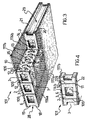
- FIGS 3 and 4 schematically show further embodiments of the construction element 1 according to the invention.
- reference 101 indicates a wall element used for instance for erecting bearing and partition walls in a building.
- the wall element 101 has in this case two pairs of side lugs, generally denoted by numerals 18-21, extending from the opposite lateral sides 28, 29 of the central body 2.
- the wall element 101 includes a plurality of reinforcing section bars 109 transversely extending across the central body 2 of the construction element throughout the whole thickness thereof.
- both opposite fins 11, 12 of the reinforcing section bars 109 lie substantially flush with and parallel to the opposite faces 6, 7 of the wall element 101.
- the latter may then include a pair of laths 116a, 116b, each adapted to support a respective covering layer 117a, 117b, such as plaster, welded to the opposite fins 11, 12 of the reinforcing section bars 109.
- the wall element 101 may include a panel 22 of gypsum paperboard, wood, rigid plastics, or another suitable material for decorative and/or structural purposes, instead of the lath 116a, for example.
- This panel 22 is fixed to the fins 11 of the reinforcing section bars 109 on the face 7 of the wall element 101 in a manner known per se, such as by a set of screws or dowels, not shown.
- the wall elements 101 of the invention may advantageously achieve load-bearing characteristics, that is being able to independently withstand possible static loads applied thereto.
Landscapes
- Engineering & Computer Science (AREA)
- Architecture (AREA)
- Physics & Mathematics (AREA)
- Electromagnetism (AREA)
- Civil Engineering (AREA)
- Structural Engineering (AREA)
- Manufacturing & Machinery (AREA)
- Mechanical Engineering (AREA)
- Building Environments (AREA)
- Finishing Walls (AREA)
- Laminated Bodies (AREA)
- Floor Finish (AREA)
Claims (48)
- Ein selbsttragendes Bauelement (1, 101) aus expandiertem Kunststoff, mit:dadurch gekennzeichnet, daß es ferner ein plattenähnliches Bauteil (16, 116) zum Halten wenigstens einer Schicht (17) eines geeigneten Abdeckmaterials umfaßt, wobei das plattenähnliche Bauteil (16, 116) einer Rippe (11, 12) des verstärkenden Profilstahls (8, 9, 109) zugeordnet ist, die bündig mit und im Wesentlichen parallel zu wenigstens einer der Stirnflächen (6,7) des Bauelementes (1, 101) angeordnet ist.a) einem im Wesentlichen quaderförmigen Hauptkörper (2) mit gegenüberliegenden Stirnflächen (6, 7),b) wenigstens einem verstärkenden Profilstahl (8, 9, 109), der sich zwischen den Stirnflächen (6, 7) quer durch den zentralen Hauptkörper (2) erstreckt und in dem expandierten Kunststoff eingebettet ist,
- Bauelement (1, 101) nach Anspruch 1,
dadurch gekennzeichnet, daß sich der verstärkende Profilstahl (8, 9, 109) quer durch den Hauptkörper (2) durch dessen gesamte Dicke erstreckt. - Bauelement (1, 101) nach Anspruch 2,
dadurch gekennzeichnet, daß der verstärkende Profilstahl (8, 9, 109) ein Paar gegenüberliegender Rippen (11, 12) umfaßt, die bündig mit und im Wesentlichen parallel zu den Stirnflächen (6, 7) des Bauelementes (1, 101) angeordnet sind. - Bauelement (1, 101) nach Anspruch 3,
dadurch gekennzeichnet, daß es ein Paar plattenähnlicher Bauteile (116a, 116b) zum Halten wenigstens einer Deckschicht (117a, 117b) umfaßt, wobei die Bauteile (116a, 116b) jeweils mit den gegenüberliegenden Rippen (11, 12) des verstärkenden Profilstahles (8, 9, 109) verbunden sind. - Bauelement (1, 101) nach Anspruch 3,
dadurch gekennzeichnet, daß es ferner ein steifes Abdeckelement (22) umfaßt, das mit dem verstärkenden Profilstahl (8, 9, 109) an einer relativ zu dem plattenähnlichen Bauteil (116) gegenüberliegenden Seite verbunden ist. - Bauelement (1, 101) nach Anspruch 5,
dadurch gekennzeichnet, daß das steife Abdeckelement (22) ein Paneel aus Gipspappe, Holz, einem steifen Kunststoff oder einem anderen geeigneten Material ist. - Bauelement (1, 101)nach Anspruch 3,
dadurch gekennzeichnet, daß sich der versteifende Profilstahl (8, 9, 109) in Längsrichtung in dem Hauptkörper (2) über dessen im Wesentlichen gesamte Länge erstreckt. - Bauelement (1, 101)nach Anspruch 1,
dadurch gekennzeichnet, daß der verstärkende Profilstahl (8, 9, 109) mit einer Mehrzahl von Öffnungen (13, 14, 15) ausgestattet ist, die in einem zentralen Bereich (10) desselben ausgebildet sind. - Bauelement (1, 101) nach Anspruch 8,
dadurch gekennzeichnet, daß die Öffnungen (13, 14, 15) einen Gesamtbereich aufweisen, der zwischen 10% und 60% des Gesamtoberflächenbereiches des verstärkenden Profilstahles (8, 9, 109) umfaßt. - Bauelement (1, 101), nach Anspruch 8,
dadurch gekennzeichnet, daß die Öffnungen (13, 14, 15) einen kreisförmigen Querschnitt mit einem Durchmesser von 15 bis 150 mm aufweisen. - Bauelement (1, 101) nach Anspruch 8,
dadurch gekennzeichnet, daß die Öffnungen (13, 14, 15) peripher mit einer Lippe ausgestattet sind, die von dem zentralen Bereich (10) vorsteht und vollständig in dem expandierten Kunststoff eingebettet ist. - Bauelement (1, 101) nach Anspruch 8,
dadurch gekennzeichnet, daß die Öffnungen (13, 14, 15) mit einem oder mehreren vorstehenden Bereichen ausgestattet sind, die um deren Umfangsrand verteilt und winkelig gegeneinander versetzt sind, wobei die vorstehenden Bereiche vollständig in dem expandierten Kunststoff eingebettet sind. - Bauelement (1, 101) nach Anspruch 1,
dadurch gekennzeichnet, daß der verstärkende Profilstahl (8, 9, 109) eine Dicke von 0,4 bis 1,2 mm aufweist. - Bauelement (1, 101) nach Anspruch 1,
dadurch gekennzeichnet, daß das plattenähnliche Bauteil (16) zum Halten wenigstens einer Abdeckschicht (17) gegenüberliegende laterale Bereiche (16b) umfaßt, die wenigstens teilweise bündig mit gegenüberliegenden lateralen Seiten (28, 29) des Bauelementes (1, 101) angeordnet sind. - Bauelement (1, 101) nach Anspruch 1,
dadurch gekennzeichnet, daß das plattenähnliche Bauteil (16, 116) zu Halten wenigstens einer Abdeckschicht (17) ein gestreckter, metallischer Maschendraht ist, der im Wesentlichen aus einem rombenförmigen Netz besteht, das ein Rombenverhältnis bezüglich der Länge zur Höhe von 2:1 aufweisen. - Bauelement (1, 101) nach Anspruch 15,
dadurch gekennzeichnet, daß der gestreckte Maschendraht eine Dicke von 0,4 bis 1,5 mm aufweist. - Bauelement (1, 101) nach Anspruch 1,
dadurch gekennzeichnet, daß es eine Mehrzahl verstärkter Profilstähle (8, 9) umfaßt, die sich quer durch den Hauptkörper (2) zwischen den gegenüberliegenden Stirnflächen (6, 7) erstrecken und in dem expandierten Kunststoff eingebettet sind, die verstärkenden Profilstähle (8, 9) im Wesentlichen z-förmig sind und über einer longitudinalen Symmetrieebene (y-y) des Bauelementes (1, 101) spiegelbildlich angeordnet sind, und die verstärkenden Profilstähle (8,9) einen zentralen Bereich (10) und ein Paar entsprechender unterer (11) und oberer (12) Rippen umfassen, die sich von den Enden des zentralen Bereiches (10) in entgegengesetzten Richtungen senkrecht erstrecken. - Bauelement (1, 101) nach Anspruch 17,
dadurch gekennzeichnet, daß die obere Rippe (12) der verstärkenden Profilstähle (8, 9) einen ersten Bereich, (12a), der sich im Wesentlichen senkrecht zu dem zentralen Bereich (10) der verstärkenden Profilstähle (8, 9) erstreckt, und einen zweiten Endbereich (12b) aufweist, der zu dem zentralen Bereich (10) gebogen ist. - Bauelement (1, 101) nach Anspruch 17,
dadurch gekennzeichnet, daß sich die obere Rippe (12) der verstärkenden Profilstähle (8, 9) von dem zentralen Bereich (10) der verstärkenden Profilstähle (8,9) zu den lateralen Seiten (28, 29) des Bauelementes (1, 101) erstreckt. - Bauelement (1, 101) nach einem der vorhergehenden Ansprüche
dadurch gekennzeichnet, daß es ferner eine Schicht (17) aus Gips, Zement oder mit Fasern eines geeigneten Materials verstärktem Zement umfaßt, die mit dem haltenden plattenähnlichen Bauteil (16, 116) verbunden ist. - Verfahren zum Herstellen eines Bauelementes (1, 101) nach einem der Ansprüche 1 bis 20,
dadurch gekennzeichnet, daß es die Schritte umfaßt:Verbinden eines plattenähnlichen Bauteiles (16, 116) zum Halten wenigstens einer Schicht (17) eines geeigneten Abdeckmaterials mit einer Rippe (11, 12), die sich von einem Ende eines verstärkenden Profilstahles erstreckt (8, 9, 109),Anordnen des so verbundenen verstärkenden Profilstahles (8, 9, 109) und des plattenähnlichen Bauteiles (16, 116) in einen Formsitz einer geeigneten Vorrichtung zum Formen von Kunststoff,Zuführen expandierbarer Kunststoffgranulate in den Formsitz,Expandieren und dann Verbinden der Kunststoffgranulate in dem Formssitz, um so den verstärkenden Profilstahl (8, 9, 109) in eine Masse expandierten Kunststoffes mit einer vorbestimmten Form einzubetten und das plattenähnliche Bauteil (16, 116) wenigstens teilweise im Wesentlichen bündig mit der Masse expandierten Kunststoffes zu halten. - Verfahren nach Anspruch 21,
dadurch gekennzeichnet, daß es einen zusätzlichen Schritt eines Herausschälens wenigstens eines Teils des plattenähnlichen Bauteiles (16, 116) aus der Masse expandiertem Kunststoffes umfaßt. - Verfahren nach Anspruch 22,
dadurch gekennzeichnet, daß das plattenähnliche Bauteil (16, 116) aus der Masse expandierten Kunststoffes mittels einer Wärmebehandlung herausgeschält wird, die ausgeführt wird, indem eine Schicht eines auf eine Temperatur von 220° bis 260° erwärmten warmen Gases auf die Masse zugeführt wird. - Verfahren nach Anspruch 23,
dadurch gekennzeichnet, daß der Wärmebehandlung ein Schritt eines Wegkratzens einer Hautschicht der Masse expandierten Kunststoffes vorgelagert wird. - Verfahren zum Herstellen eines Bauelementes (1, 101) nach einem der Ansprüche 1 bis 20, dadurch gekennzeichnet, daß es die Schritte umfaßt:Anordnen eines verstärkenden Profilstahles (8, 9, 109), der an einem Ende mit wenigstens einer Rippe (11, 12) ausgestattet ist, in einen Formsitz einer geeigneten Vorrichtung zum Formen von Kunststoff,Zuführen expandierbarer Kunststoffgranulate in den Formsitz,Expandieren und dann Verbinden der Kunststoffgranulate in dem Formsitz, um so den verstärkenden Profilstahl (8, 9, 109) in eine Masse expandierten Kunststoffes mit einer vorbestimmten Form einzubetten und die wenigstens eine Rippe (11, 12) im Wesentlichen bündig mit der Masse expandiertem Kunststoffes zu halten,Verbinden eines plattenähnlichen Bauteiles (16, 116) zum Halten wenigstens einer Schicht (17) eines geeigneten Abdeckmaterials mit der wenigstens einen Rippe (11, 12) des verstärkenden Profilstahles (8, 9, 109).
- Verfahren nach Anspruch 25,
dadurch gekennzeichnet, daß es einen zusätzlichen Schritt eines Herausschälens der wenigstens einen Rippe (11, 12) des verstärkenden Profilstahles (8, 9, 109) aus der Masse expandierten Kunststoffes umfaßt. - Verfahren nach Anspruch 26,
dadurch gekennzeichnet, daß das plattenähnliche Bauteil (16, 116) aus der Masse expandierten Kunststoffes mittels einer Wärmebehandlung herausgeschält wird, die ausgeführt wird, indem eine Schicht eines auf eine Temperatur von 220° bis 260° erwärmten warmen Gases auf die Masse geführt wird. - Verfahren nach Anspruch 23,
dadurch gekennzeichnet, daß der Wärmebehandlung ein Schritt eines Wegkratzens einer Hautschicht der Masse expandierten Kunststoffes vorgelagert wird. - Verfahren nach Anspruch 21 oder 25,
dadurch gekennzeichnet, daß das plattenähnliche Bauteil (16, 116) und der verstärkende Profilstahl (8, 9, 109) durch Schweißen miteinander verbunden sind. - Bodenplatte, mit:einer Mehrzahl selbststragender Bauelemente (1) aus expandiertem Kunststoff, die seitlich nebeneinander angeordnet sind, wobei die Teile (1) umfassen:a) einen im Wesentlichen rombenförmigen Hauptkörper (2) der mit gegenüberliegenden oberen (6) und unteren (7) Stirnflächen und mit gegenüberliegenden lateralen Seiten (28, 29) ausgestattet ist,b) wenigstens einem verstärkenden Profilstahl (8, 9), der sich zwischen den gegenüberliegenden oberen (6) und unteren (7) Stirnflächen quer durch den Hauptkörper (2) erstreckt und in dem expandierten Kunststoff eingebettet ist,c) einem plattenähnlichen Bauteil (16) zum Halten wenigstens einer Schicht (17) eines geeigneten Abdeckmaterials, wobei das plattenähnliche Bauteil (16) mit einer Rippe (11, 12) des verstärkenden Profilstahls (8, 9) verbunden ist, bündig mit und im Wesentlichen parallel zu wenigstens einer der gegenüberliegenden oberen (6) und unteren (7) Stirnflächen des Bauelementes (1) angeordnet ist und gegenüberliegende laterale Bereiche (16b) umfaßt, die wenigstens teilweise bündig mit den gegenüberliegenden lateralen Seiten (28, 29) des Bauelementes (1) mit angeordnet sind,einem Zementgußteil, das in einem Hohlraum untergebracht ist, der zwischen den gegenüberliegenden lateralen Seiten (28, 29) benachbarter Bauelemente (1) der Mehrzahl definiert ist,wobei es die lateralen Bereiche (16b) des plattenähnlichen Bauteiles (16) erlauben, das plattenähnliche Bauteil (16) fest an den Zementgußteil zu verankern.
- Bodenplatte nach Anspruch 30,
dadurch gekennzeichnet, daß die Bauelemente (1) mittels einer im Wesentlichen aufeinander abgestimmten Verbindung miteinander verbunden sind. - Bodenplatte nach Anspruch 31,
dadurch gekennzeichnet, daß die aufeinander abgestimmte Verbindung eine Nut (23) und eine Rippe (24) aufeinanander abgestimmte Form umfaßt, die sich von einem Paar von Absätzen (4,5) erstrecken, die sich entlang der gegenüberliegenden lateralen Seiten (28, 29) des Bauelementes (1) über dessen gesamte Länge lateral und in Längsrichtung erstrecken. - Bodenplatte nach Anspruch 31,
dadurch gekennzeichnet, daß die lateralen Bereiche (16b) des plattenähnlichen Bauteiles (16) einen Abschnitt umfassen, der sich bündig mit den Bauelementen (1) in den Nuten (26, 27) erstreckt, die longitudinal der Länge nach in den gegenüberliegenden lateralen Seiten (28, 29) des Bauelementes (1) über den Absätzen (4, 5) ausgebildet sind. - Bodenplatte nach Anspruch 32, ferner mit einer Mehrzahl verstärkender Stäbe, die in dem Zementgußteil eingebettet sind.
- Bodenplatte nach Anspruch 34,
dadurch gekennzeichnet, daß die Absätze (4, 5) mit einer Mehrzahl vertikaler Rippen (25) ausgestattet sind, die teilungsartig über die Länge des Bauelementes (1) angeordnet sind, um die verstärkenden Stäbe in einem vorbestimmten Abstand von den übrigen Absätzen (4, 5) zu halten. - Bodenplatte nach Anspruch 30,
dadurch gekennzeichnet, daß sich der verstärkende Profilstahl (8, 9) quer durch den Hauptkörper (2) durch dessen gesamte Dicke erstreckt. - Bodenplatte nach Anspruch 30,
dadurch gekennzeichnet, daß sich der verstärkende Profilstahl (8, 9) in Längsrichtung in dem Hauptkörper (2) über dessen im Wesentlichen gesamte Länge erstreckt. - Bodenplatte nach Anspruch 30,
dadurch gekennzeichnet, daß der verstärkende Profilstahl (8, 9) mit einer Mehrzahl von Öffnungen (13, 14, 15) ausgestattet ist, die in einem zentralen Bereich (10) desselben ausgebildet sind. - Bodenplatte nach Anspruch 30,
dadurch gekennzeichnet, daß das plattenähnliche Bauteil (16) zum Halten wenigstens einer Abdeckschicht (17) ein gestreckter metallischer Maschendraht (16) ist, der im Wesentlichen aus einem rombenförmigen Netz besteht, das ein Rombenverhältnis bezüglich der Länge zur Höhe von 2:1 aufweist. - Bodenplatte nach einem der Ansprüche 30 bis 39,
dadurch gekennzeichnet, daß sie ferner eine Schicht (17) aus Gips, Zement oder mit Fasern eines geeigneten Materials verstärktem Zement umfaßt, die mit dem haltenden plattenähnlichen Bauteil (16) verbunden ist. - Modulares Wandelement, mit:einer Mehrzahl selbststragender Bauelemente (101) aus expandiertem Kunststoff, die seitlich nebeneinander angeordnet sind, wobei die Teile (1) umfassen:a) einen im Wesentlichen quaderförmigen Hauptkörper (2) der mit gegenüberliegenden oberen (6) und unteren (7) Stirnflächen, mit gegenüberliegenden lateralen Seiten (28, 29) und wenigstens einem Hohlraum (3) ausgestattet ist,b) wenigstens einen verstärkenden Profilstahl (109), der sich zwischen den gegenüberliegenden oberen (6) und unteren (7) Stirnflächen quer durch den Hauptkörper (2) erstreckt und in dem expandierten Kunststoff eingebettet ist, wobei der wenigstens eine verstärkende Profilstahl (119) ein Paar Rippen (11, 12) aufweist, die bündig mit und im wesentlichen parallel zu den gegenüberliegenden oberen (6) und unteren (7) Stirnflächen des Bauelementes (101) angeordnet sind,c) wenigstens einem plattenbähnlichen Bauteil (116a, 116b) zum Halten wenigstens einer Schicht (117a, 117b) eines geeigneten Abdeckmaterials, wobei das wenigstens eine plattenähnliche Bauteil (116a, 116b ) mit wenigstens einer der Rippen (11,12) verbunden ist,einem Zementgußteil, das in dem wenigstens einen Hohlraum (3) der selbststragenden Bauelemente (101) untergebracht ist.
- Modulares Wandelement nach Anspruch 41, mit einem Paar plattenähnlicher Bauteile (116a, 116b) zum Halten entsprechender Abdeckschichten (117a, 117b), wobei die plattenähnlichen Bauteile (116a, 116b) jeweils mit den gegenüberliegenden Rippen (11, 12) des verstärkenden Profilstahles (109) verbunden sind.
- Modulares Wandelement nach Anspruch 41, mit einem plattenähnlichen Bauteil (116b) zum Halten einer entsprechenden Schicht (117b) eines geeigneten Abdeckmaterials, das mit einer ersten (12) der Rippen (11, 12) des verstärkenden Profilstahls (109) verbunden ist, und einem steifen Abdeckelement (22), daß mit einer Zweiten (11) der Rippen (11, 12) relativ zu dem plattenähnlichen Bauteil (116b) relativ an einer relativ gegenüberliegenden Seite verbunden ist.
- Modulares Wandelement nach Anspruch 43,
dadurch gekennzeichnet, daß das steife Abdeckelement (22) ein Paneel aus Gipspappe, Holz, einem steifen Kunststoff oder einem anderem geeigneten Material ist. - Modulares Wandelement nach Anspruch 43,
dadurch gekennzeichnet, daß sich der verstärkende Profilstahl (109) in dem Hauptkörper (2) in Längsrichtung über dessen im Wesentlichen gesamte Länge erstreckt. - Modulares Wandelement nach Anspruch 41,
dadurch gekennzeichnet, daß der verstärkende Profilstahl (109) mit einer Mehrzahl von Öffnungen (13, 14, 15) ausgestattet ist, die in einem zentralen Bereich (10) desselben ausgebildet sind. - Modulares Wandelement nach Anspruch 41,
dadurch gekennzeichnet, daß das wenigstens eine plattenähnliche Bauteil (116a, 116b) zum Halten der wenigstens einen Abdeckschicht (117a, 117b) ein gestreckter metallischer Maschendraht ist, der im Wesentlichen aus einem rombenförmigen Netz besteht, das ein Rombenverhältnis bezüglich der Länge zur Höhe von 2:1 aufweist. - Modulares Wandelement nach einem der Ansprüche 41 bis 47,
dadurch gekennzeichnet, daß es ferner eine Schicht (117a 117b) aus Gips, Zement oder mit Fasern eines geeigneten Materials verstärktem Zement umfaßt, die mit dem wenigstens einen haltenden plattenähnlichen Bauteil (116a, 116b) verbunden ist.
Applications Claiming Priority (3)
| Application Number | Priority Date | Filing Date | Title |
|---|---|---|---|
| ITMI962137 | 1996-10-15 | ||
| IT96MI002137A IT1284961B1 (it) | 1996-10-15 | 1996-10-15 | Elemento costruttivo autoportante in materia plastica espansa in particolare per la realizzazione di solai e pareti di edifici |
| PCT/EP1997/005671 WO1998016703A2 (en) | 1996-10-15 | 1997-10-09 | Self-supporting construction element of expanded plastics, in particular for manufacturing floor elements and walls of buildings in general |
Publications (2)
| Publication Number | Publication Date |
|---|---|
| EP0932733A1 EP0932733A1 (de) | 1999-08-04 |
| EP0932733B1 true EP0932733B1 (de) | 2002-04-03 |
Family
ID=11375037
Family Applications (1)
| Application Number | Title | Priority Date | Filing Date |
|---|---|---|---|
| EP97945836A Expired - Lifetime EP0932733B1 (de) | 1996-10-15 | 1997-10-09 | Selbsttragendes bauelement aus expandiertem plastik, insbesondere für die herstellung von bodenplatten und gebäudewänden im allgemeinen |
Country Status (8)
| Country | Link |
|---|---|
| US (1) | USRE44642E1 (de) |
| EP (1) | EP0932733B1 (de) |
| AT (1) | ATE215650T1 (de) |
| DE (1) | DE69711658T2 (de) |
| ES (1) | ES2175476T3 (de) |
| IT (1) | IT1284961B1 (de) |
| RU (1) | RU2211897C2 (de) |
| WO (1) | WO1998016703A2 (de) |
Families Citing this family (17)
| Publication number | Priority date | Publication date | Assignee | Title |
|---|---|---|---|---|
| IT1302499B1 (it) * | 1998-09-18 | 2000-09-05 | Domenico Sambataro | Cassero a perdere per solai |
| US6272749B1 (en) | 1999-11-15 | 2001-08-14 | Lite-Form International | Cast-in-place concrete deck system |
| IT1319246B1 (it) * | 2000-10-27 | 2003-09-26 | Plastedil Sa | Elemento costruttivo composito, in particolare per la realizzazione distrutture di rivestimento o strutture di parete di edifici. |
| US6817150B1 (en) | 2003-03-20 | 2004-11-16 | Patrick E. Boeshart | Form system for poured concrete |
| ITMI20030985A1 (it) * | 2003-05-16 | 2004-11-17 | Plastedil Sa | Elemento costruttivo composito, in particolare per la realizzazione di strutture di parete per edifici e procedimento per la sua fabbricazione. |
| ITMI20041644A1 (it) * | 2004-08-11 | 2004-11-11 | Eni Spa | Procedimento per lo stoccaggio di zolfo ad emissione zero |
| FR2878872B1 (fr) * | 2004-12-03 | 2007-01-19 | Isobox Technologies Soc Par Ac | Entrevous isolant de plancher en materiau plastique expanse et son procede de fabrication |
| WO2006079355A1 (en) * | 2005-01-28 | 2006-08-03 | Domopan, S.P.A. | Panel made from expanded plastic meterial for building slab construction, slab and construction method comprising such a panel |
| ITPD20050263A1 (it) * | 2005-09-13 | 2007-03-14 | American Entpr Srl | Pannello di solaio prefabbricato attrezzato con impiego di materiale alleggerito |
| ME00560A (en) * | 2005-11-15 | 2011-12-20 | Possibility of special lightening insulating and reinforcing intermediate floor contractions | |
| EA010268B1 (ru) * | 2007-05-21 | 2008-06-30 | Вейнгарт, Валентин Павлович | Способ изготовления термоструктурных панелей и оборудование для его осуществления |
| ITTO20120370A1 (it) * | 2012-04-26 | 2013-10-27 | Bazzica Engineering S R L | Solaio modulare con cassero a perdere |
| ITMI20121022A1 (it) | 2012-06-12 | 2012-09-11 | Dst Const Ltd | Elemento modulare in polistirene espanso sinterizzato per la formazione di solai in calcestruzzo armato e solaio in calcestruzzo armato comprendente una pluralita' di detti elementi modulari. |
| CN104641055A (zh) * | 2012-06-29 | 2015-05-20 | 沃尔夫冈·阿道夫·宾德 | 建造系统及方法 |
| RU2627507C1 (ru) * | 2016-06-27 | 2017-08-08 | Владимир Степанович Григорчук | Бароподъемная панель |
| ES2718806B2 (es) * | 2018-01-04 | 2020-03-12 | Dinatec Tecnica S L | Base modular de construccion |
| RU2707607C1 (ru) * | 2019-04-24 | 2019-11-28 | Владимир Степанович Григорчук | Бароподъёмная панель |
Family Cites Families (18)
| Publication number | Priority date | Publication date | Assignee | Title |
|---|---|---|---|---|
| US2324916A (en) * | 1940-05-02 | 1943-07-20 | United States Gypsum Co | Reinforced structural element |
| US2902854A (en) * | 1956-03-12 | 1959-09-08 | Tecfab Inc | Prefabricated roof or ceiling panel |
| US3313073A (en) * | 1962-09-24 | 1967-04-11 | Foam Products Corp | Joint assemblies for insulation panels |
| GB1130727A (en) * | 1965-06-09 | 1968-10-16 | Rohpappen Fabrik Worms Zweigni | Foamed plastics slab with embedded reinforcement |
| DK111462B (da) * | 1965-06-09 | 1968-08-26 | Rohpappen Fab Worms Zweigniede | Skumstofplade med afstivningsorganer. |
| FR2322984A1 (fr) * | 1975-09-05 | 1977-04-01 | Solai Vignola Fabiani Orlando | Elements de construction prefabriques en materiau expanse-ciment, leur procede de prefabrication et installations appropriees |
| US4125981A (en) * | 1976-05-14 | 1978-11-21 | Caledonian Moroccan Construction Ltd. S.A. | Reinforced structures |
| US4206267A (en) * | 1977-01-07 | 1980-06-03 | Otto Jungbluth | Composite structural material |
| FR2570739A1 (fr) * | 1984-09-26 | 1986-03-28 | Serre Michel | Module pour la fabrication de planchers |
| FR2615229B1 (fr) * | 1987-05-12 | 1992-08-14 | Lemasson Paul | Panneau prefabrique pour la construction, notamment de caveaux |
| US4841702A (en) * | 1988-02-22 | 1989-06-27 | Huettemann Erik W | Insulated concrete building panels and method of making the same |
| FR2662730B1 (fr) | 1990-05-29 | 1992-09-25 | Eurostyrene Sarl | Procede de fabrication de hourdis autocoffrants et isolants, dispositif pour la mise en óoeuvre de ce procede et hourdis ainsi obtenus. |
| US5245809A (en) * | 1991-05-16 | 1993-09-21 | Harrington Bruce E | Urethane insulating panel and method |
| US5381635A (en) * | 1991-08-27 | 1995-01-17 | Royal Wall Systems, Inc. | Construction wall panel and panel structure |
| RU2054507C1 (ru) * | 1993-07-29 | 1996-02-20 | Государственный центральный научно-исследовательский и проектно-экспериментальный институт комплексных проблем строительных конструкций и сооружений им.В.А.Кучеренко | Способ изготовления термоармопакета стенового ограждения |
| IT1265542B1 (it) * | 1993-10-05 | 1996-11-22 | Ntc Srl | Elemento prefabbricato per la realizzazione di solai di edifici. |
| US5638651A (en) * | 1994-08-25 | 1997-06-17 | Ford; Vern M. | Interlocking panel building system |
| US5729936A (en) * | 1995-10-03 | 1998-03-24 | Maxwell; James F. | Prefab fiber building construction |
-
1996
- 1996-10-15 IT IT96MI002137A patent/IT1284961B1/it active IP Right Grant
-
1997
- 1997-10-09 RU RU99110198/03A patent/RU2211897C2/ru active
- 1997-10-09 AT AT97945836T patent/ATE215650T1/de not_active IP Right Cessation
- 1997-10-09 ES ES97945836T patent/ES2175476T3/es not_active Expired - Lifetime
- 1997-10-09 WO PCT/EP1997/005671 patent/WO1998016703A2/en not_active Ceased
- 1997-10-09 DE DE69711658T patent/DE69711658T2/de not_active Expired - Lifetime
- 1997-10-09 EP EP97945836A patent/EP0932733B1/de not_active Expired - Lifetime
-
2003
- 2003-10-09 US US10/681,354 patent/USRE44642E1/en not_active Expired - Lifetime
Also Published As
| Publication number | Publication date |
|---|---|
| IT1284961B1 (it) | 1998-05-28 |
| ITMI962137A1 (it) | 1998-04-15 |
| ATE215650T1 (de) | 2002-04-15 |
| WO1998016703A2 (en) | 1998-04-23 |
| USRE44642E1 (en) | 2013-12-17 |
| RU2211897C2 (ru) | 2003-09-10 |
| DE69711658T2 (de) | 2002-10-31 |
| ES2175476T3 (es) | 2002-11-16 |
| DE69711658D1 (de) | 2002-05-08 |
| EP0932733A1 (de) | 1999-08-04 |
Similar Documents
| Publication | Publication Date | Title |
|---|---|---|
| US6298622B1 (en) | Self-supporting construction element of expanded plastics, in particular for manufacturing floor elements and walls of buildings in general | |
| EP0932733B1 (de) | Selbsttragendes bauelement aus expandiertem plastik, insbesondere für die herstellung von bodenplatten und gebäudewänden im allgemeinen | |
| US5809725A (en) | Sectional nog structure for fastening a covering element to a foamed plastic slab and construction element incorporating said structure | |
| EP0208529B1 (de) | Gebäudekonstruktionen aus bewehrtem Beton | |
| US3676967A (en) | Forms for concrete wall construction | |
| AU2019210599B2 (en) | Improved mesh, mesh panels, composite building elements and method of reinforcing and articles reinforced by the method, duct and riser walls and methods for their construction | |
| US20030029107A1 (en) | Building element | |
| HUT68939A (en) | Sheet metal structural member, construction panel and method of construction | |
| EP0693597A1 (de) | Modulares Dübelsystem zur Befestigung eines Verkleidungselementes an einer Kunststoffschaumplatte und Konstruktionselement mit diesem System | |
| US5906081A (en) | Wall construction and method of manufacturing a wall construction | |
| CA2522163C (en) | Composite construction element, in particular for making wall structures for buildings and process for its manufacture | |
| US3864888A (en) | Apparatus and method for employing gypsum board as forms for poured concrete ceiling and floor structures | |
| US7251919B2 (en) | Lightweight building component | |
| FI84847C (fi) | Stomkonstruktion foer samverkansbalk. | |
| WO2006079355A1 (en) | Panel made from expanded plastic meterial for building slab construction, slab and construction method comprising such a panel | |
| JPS5849290Y2 (ja) | 建物用煉瓦壁の構造 | |
| FI63465C (fi) | Form foer bjaelklag | |
| CA1169236A (en) | Method of making a building panel | |
| EP1646755B1 (de) | Fertigteilbodenelement mit äusserer verstärkung und verfahren zur herstellung solch eines fertigteilbodenelements | |
| AU784217B2 (en) | A joint | |
| EP0695841A1 (de) | Selbsttragende Platte für Verkleidungen und/oder Decken im Innenausbau | |
| CN86107290A (zh) | 加筋混凝土建筑结构 | |
| JPH10159246A (ja) | 間仕切壁 | |
| MXPA97008508A (en) | Wall construction and method for the manufacture of a pa construction | |
| CS224658B1 (cs) | Způsob výroby keramického stěnového dílce |
Legal Events
| Date | Code | Title | Description |
|---|---|---|---|
| PUAI | Public reference made under article 153(3) epc to a published international application that has entered the european phase |
Free format text: ORIGINAL CODE: 0009012 |
|
| 17P | Request for examination filed |
Effective date: 19990419 |
|
| AK | Designated contracting states |
Kind code of ref document: A1 Designated state(s): AT DE ES FR GB IT NL |
|
| GRAG | Despatch of communication of intention to grant |
Free format text: ORIGINAL CODE: EPIDOS AGRA |
|
| 17Q | First examination report despatched |
Effective date: 20010202 |
|
| GRAG | Despatch of communication of intention to grant |
Free format text: ORIGINAL CODE: EPIDOS AGRA |
|
| GRAG | Despatch of communication of intention to grant |
Free format text: ORIGINAL CODE: EPIDOS AGRA |
|
| GRAH | Despatch of communication of intention to grant a patent |
Free format text: ORIGINAL CODE: EPIDOS IGRA |
|
| GRAH | Despatch of communication of intention to grant a patent |
Free format text: ORIGINAL CODE: EPIDOS IGRA |
|
| REG | Reference to a national code |
Ref country code: GB Ref legal event code: IF02 |
|
| GRAA | (expected) grant |
Free format text: ORIGINAL CODE: 0009210 |
|
| AK | Designated contracting states |
Kind code of ref document: B1 Designated state(s): AT DE ES FR GB IT NL |
|
| PG25 | Lapsed in a contracting state [announced via postgrant information from national office to epo] |
Ref country code: NL Free format text: LAPSE BECAUSE OF FAILURE TO SUBMIT A TRANSLATION OF THE DESCRIPTION OR TO PAY THE FEE WITHIN THE PRESCRIBED TIME-LIMIT Effective date: 20020403 Ref country code: AT Free format text: LAPSE BECAUSE OF FAILURE TO SUBMIT A TRANSLATION OF THE DESCRIPTION OR TO PAY THE FEE WITHIN THE PRESCRIBED TIME-LIMIT Effective date: 20020403 |
|
| REF | Corresponds to: |
Ref document number: 215650 Country of ref document: AT Date of ref document: 20020415 Kind code of ref document: T |
|
| REF | Corresponds to: |
Ref document number: 69711658 Country of ref document: DE Date of ref document: 20020508 |
|
| ET | Fr: translation filed | ||
| NLV1 | Nl: lapsed or annulled due to failure to fulfill the requirements of art. 29p and 29m of the patents act | ||
| PG25 | Lapsed in a contracting state [announced via postgrant information from national office to epo] |
Ref country code: GB Free format text: LAPSE BECAUSE OF NON-PAYMENT OF DUE FEES Effective date: 20021009 |
|
| REG | Reference to a national code |
Ref country code: ES Ref legal event code: FG2A Ref document number: 2175476 Country of ref document: ES Kind code of ref document: T3 |
|
| PLBE | No opposition filed within time limit |
Free format text: ORIGINAL CODE: 0009261 |
|
| STAA | Information on the status of an ep patent application or granted ep patent |
Free format text: STATUS: NO OPPOSITION FILED WITHIN TIME LIMIT |
|
| 26N | No opposition filed |
Effective date: 20030106 |
|
| GBPC | Gb: european patent ceased through non-payment of renewal fee |
Effective date: 20021009 |
|
| REG | Reference to a national code |
Ref country code: FR Ref legal event code: PLFP Year of fee payment: 19 |
|
| REG | Reference to a national code |
Ref country code: FR Ref legal event code: PLFP Year of fee payment: 20 |
|
| PGFP | Annual fee paid to national office [announced via postgrant information from national office to epo] |
Ref country code: FR Payment date: 20161025 Year of fee payment: 20 Ref country code: DE Payment date: 20161027 Year of fee payment: 20 |
|
| PGFP | Annual fee paid to national office [announced via postgrant information from national office to epo] |
Ref country code: IT Payment date: 20161004 Year of fee payment: 20 Ref country code: ES Payment date: 20161026 Year of fee payment: 20 |
|
| REG | Reference to a national code |
Ref country code: DE Ref legal event code: R071 Ref document number: 69711658 Country of ref document: DE |
|
| REG | Reference to a national code |
Ref country code: ES Ref legal event code: FD2A Effective date: 20180126 |
|
| PG25 | Lapsed in a contracting state [announced via postgrant information from national office to epo] |
Ref country code: ES Free format text: LAPSE BECAUSE OF EXPIRATION OF PROTECTION Effective date: 20171010 |