EP0930687A2 - Cable gland - Google Patents
Cable gland Download PDFInfo
- Publication number
- EP0930687A2 EP0930687A2 EP99100268A EP99100268A EP0930687A2 EP 0930687 A2 EP0930687 A2 EP 0930687A2 EP 99100268 A EP99100268 A EP 99100268A EP 99100268 A EP99100268 A EP 99100268A EP 0930687 A2 EP0930687 A2 EP 0930687A2
- Authority
- EP
- European Patent Office
- Prior art keywords
- cable
- cable gland
- contact
- pressure
- gland according
- Prior art date
- Legal status (The legal status is an assumption and is not a legal conclusion. Google has not performed a legal analysis and makes no representation as to the accuracy of the status listed.)
- Granted
Links
Images


Classifications
-
- H—ELECTRICITY
- H02—GENERATION; CONVERSION OR DISTRIBUTION OF ELECTRIC POWER
- H02G—INSTALLATION OF ELECTRIC CABLES OR LINES, OR OF COMBINED OPTICAL AND ELECTRIC CABLES OR LINES
- H02G15/00—Cable fittings
- H02G15/02—Cable terminations
- H02G15/04—Cable-end sealings
-
- H—ELECTRICITY
- H02—GENERATION; CONVERSION OR DISTRIBUTION OF ELECTRIC POWER
- H02G—INSTALLATION OF ELECTRIC CABLES OR LINES, OR OF COMBINED OPTICAL AND ELECTRIC CABLES OR LINES
- H02G3/00—Installations of electric cables or lines or protective tubing therefor in or on buildings, equivalent structures or vehicles
- H02G3/02—Details
- H02G3/06—Joints for connecting lengths of protective tubing or channels, to each other or to casings, e.g. to distribution boxes; Ensuring electrical continuity in the joint
- H02G3/0616—Joints for connecting tubing to casing
- H02G3/0625—Joints for connecting tubing to casing with means for preventing disengagement of conductors
- H02G3/0666—Joints for connecting tubing to casing with means for preventing disengagement of conductors with means clamping the armour of the conductor
-
- H—ELECTRICITY
- H02—GENERATION; CONVERSION OR DISTRIBUTION OF ELECTRIC POWER
- H02G—INSTALLATION OF ELECTRIC CABLES OR LINES, OR OF COMBINED OPTICAL AND ELECTRIC CABLES OR LINES
- H02G3/00—Installations of electric cables or lines or protective tubing therefor in or on buildings, equivalent structures or vehicles
- H02G3/02—Details
- H02G3/06—Joints for connecting lengths of protective tubing or channels, to each other or to casings, e.g. to distribution boxes; Ensuring electrical continuity in the joint
- H02G3/0616—Joints for connecting tubing to casing
- H02G3/0691—Fixing tubing to casing by auxiliary means co-operating with indentations of the tubing, e.g. with tubing-convolutions
Definitions
- the invention relates to a cable gland comprising one with a defined electrical potential lying component, in particular a housing, connectable Nozzle, one that can be inserted into an interior of the nozzle Seal and a pressure element that can be screwed to the socket, which on the seal in the sense of an application the same to a jacket through the cable gland passed cable acts.
- Such cable glands are from the prior art known. With these cable glands, the cable should be tight completed with the component into which the nozzle can be screwed is to be connected.
- the object of the invention is therefore a cable gland and to create a cable assembly that one optimal and as protected as possible installation of a cable enables.
- This task is done with a cable gland at the beginning described type according to the invention solved in that a side of the pressure element opposite the neck a receptacle is provided in which one end of the Sheath of the cable surrounding and electrical over its length conductive cable protection hose can be used, that a connectable to the pressure element clamping element is provided with which the end of the cable protection conduit connectable mechanically and electrically to the pressure element is and that the pressure element with the nozzle and the Stubs are electrically connected to the component.
- the cable protection hose has a mechanical Protection for the cable provides and also the cable protection hose additionally an electrical shield for the Cable represents, by the electrical connection of the Cable protection hose ultimately with the component an excellent and in particular complete shielding of the cable is also guaranteed in the area of the cable gland.
- the seal between the cable and the nozzle advantageous to the extent that even in the Cable protection hose penetrating dirt or water this cannot get into the component, especially the housing and vice versa also no contamination from the housing in the Cable protection hose can enter.
- the solution according to the invention still has the great advantage that it is easy to install because of the cable protection hose for example then via the cable is feasible if this is connected with one end and already in the nozzle by means of the pressure element and Seal is fixed.
- a particularly cheap solution of the cable gland according to the invention stipulates that the recording as a recording for an end grommet of the cable protection conduit is formed.
- the Providing an end grommet for the cable protection conduit creates the Possibility of this mechanically stable on the one hand and on the other hand with good electrical contact on the pressure element fix.
- the end spout also has the great advantage that this sits firmly on the cable protection conduit and thus especially pre-assembled with the cable protection hose can be delivered.
- the receptacle is designed so that it one in the radial direction to a longitudinal axis of the cable gland extending contact surface for a contact element has the end spout.
- a particularly favorable design of the contact surface provides doing so that the contact surface is in the direction of an insertion opening the taper expanded.
- Such Contact surface has the advantage that it can be used even with different Tolerances in a simple way a safe and reliable Fixation of the contact element on the holder possible is.
- a particularly secure fixation of the contact element on the Contact surface is particularly possible if the contact element a also conical and the contact surface facing surface.
- the cone angle of the contact surface and the cone angle of the surface can be identical.
- cone angle between the two are different to approximate one to achieve linear contact between the two.
- a particularly favorable solution provides that the cone angle the surface of the contact element is smaller than the cone angle the contact surface, advantageously this Cone angle is made slightly smaller than that of the Contact surface.
- a particularly favorable solution provides that the contact element through one with its ring faces parallel to one Conical ring formed on the end grommet is formed.
- the electrically conductive connection can be very different Way come about.
- the end grommet be provided with contact springs which one is close to the admission and one is sufficient Provide good contact between the end grommet and the pressure element.
- a particularly favorable solution provides that the electrical Connection between the end grommet and the pressure element via an essentially linear arrangement of the two against each other he follows.
- the provision of a linear system for Making the connection between the two has the advantage that with it the highest possible surface pressure and thus the best possible electrical contact between them both can be achieved with the lowest possible contact resistance is.
- a particularly cheap solution provides that the end grommet an edge of the receptacle can be put on because it is particularly simple is for the essentially linear system between the two required edge in the receptacle to mold or mold to this while providing an edge in the area of the end grommet itself with more effort connected is.
- clamping element is a union nut comprises which can be screwed onto the pressure element, with such a cap nut, in the same way as with the pressure element, on the one hand large forces for fixing and The cable protection hose and the end grommet can be clamped are and on the other hand simple assembly is possible.
- the clamping element for example, from the union nut acted upon pressure part, which on the Contact element of the end grommet works.
- a pressure part particularly safe and permanent loading of the contact element guaranteed in the direction of the contact surface, since the Pressure ring over the entire extent of the contact element in Azimuth direction acts on the contact element.
- the Pressure part is designed to be elastic, so that this is for example can be biased by the union nut to constantly pressurized the end grommet on the pressure element Keep plant.
- a particularly secure fixation of the end grommet with the contact element is possible if the pressure part with a pressure wedge between an outside of the cable protection conduit and engages the contact element of the end grommet and thus an im essentially centered fixing of the cable protection conduit with the end grommet on the cable gland according to the invention guaranteed.
- a Shield contact element is arranged, which in electrical There is contact with the nozzle and by means of at least one in Direction of the contact bracket reaching through the cable an inner conductor area of the cable, exposed cable shield contacted.
- a particularly favorable solution provides that the contact bracket, preferably in an approximately parallel to the longitudinal axis the level of the cable gland, resiliently movable is, with this resilient movement a safe The cable shield can be contacted through the cable bracket is.
- Shield contact element has several contact brackets.
- the shield contact element Has carrier part on which the contact bracket is held are.
- the shield contact element can then be particularly inexpensive fix the socket if the shield contact element in a Recording the nozzle sits and thus in a simple manner and Way can be held securely on the neck.
- the carrier part is relative is arranged fixed to the neck and thus essentially is attached to the nozzle.
- the carrier part also an outer surface in the direction of the longitudinal axis of the cable gland is recorded.
- Shield contact element by means of at least one in a recess the claw engaging in the direction of the Longitudinal axis is fixed.
- the shield contact element advantageously provided that the shield contact element from a side of the pressure element opposite the Nozzle can be inserted into the receptacle.
- This page is usually the housing side of the nozzle.
- the receptacle connects to one of the Pressure element opposite opening of the nozzle, so that the shield contact element as close as possible to the component sits, in which the nozzle can be screwed.
- the invention relates not only to a cable gland, but also a cable assembly comprising one Cable gland and a cable held in this, wherein according to the invention the cable arrangement with a cable protection hose is provided and also according to the above described embodiments is formed.
- the advantage of this solution is already in the above discussed possibility of an advantageous shielding of the Cable.
- the cable protection hose variable in its longitudinal direction that is either is elastically stretchable or compressible, since it is an assembly of the cable protection conduit itself with both ends in the Cable glands fixed cable is possible.
- the cable protection hose one that is only electrically conductive in one spiral direction Element comprises such an electrically conductive Element, especially with variable length is easy and inexpensive to manufacture and especially in Connection to a cable shield provided in the cable anyway a sufficient additional shielding effect develops.
- Cable gland is preferably provided that the cable protection hose is provided with an end grommet.
- This end grommet can be designed in a wide variety of ways be.
- An advantageous solution provides that the End sleeve has an inner jacket for the cable protection conduit and thus with this inside the cable protection conduit on this.
- the end sleeve with the inner jacket on the Cable protection hose fixed. It would be conceivable that To glue the end grommet with the cable protection hose solder or connect using form-fitting elements. A particularly favorable positive connection provides that the end grommet engaging in the beads of the cable protection conduit own beads can be fixed on this.
- the end grommet has an outer jacket for the cable protection conduit.
- Cable gland is preferably provided that the end grommet extends from the cable protection hose to the outside extending contact element, which then to the Contact surface of the recording can be created.
- An expedient embodiment of such a receiving element stipulates that this is parallel to a conical surface extending ring is formed.
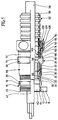
- a first embodiment of a cable gland according to the invention shown in Fig. 1 includes one as a whole designated by 10 and electrically conductive Stub, which has a cylindrical extension 12 with a Has external thread 14, which in a on a defined electrical component 16, preferably a wall of a housing can be screwed in.
- the nozzle 10 further includes a key surface section 18, which is provided with key surfaces 20 and on one a housing end 22 of the cylindrical Approach 12 opposite side immediately afterwards is arranged on the cylindrical neck 12 on the nozzle 10.
- Section 24 is used to hold a whole with 32 designated seal carrier, which with a retaining projection 34 engages in section 24 and on an inner Cylinder surface 36 of the same in the direction of a longitudinal axis 42 is led.
- the seal carrier 32 is also supported a flange surface 38 on one of the key surface section 18 facing away from flange surface 40 of the cylinder section 24 and is thereby in the direction of the longitudinal axis 42 of the cable gland against displacement in the direction of the flats section 18 secured.
- the seal carrier 32 further comprises a lamella basket 44, which in turn encloses a ring-shaped seal 46, the seal 46 further by an inner Approach 48 of the seal carrier 32 against displacement in Direction of the longitudinal axis 42 to the key surface section 18 is fixable.
- the lamellar basket 44 is in turn by a radially sloping surface 50 of the inside extending towards the longitudinal axis 42 Pressure nut 28 acted upon, which with increasing screwing the pressure nut 28 on the external thread 26 Slats of the slat basket 44 increasingly in the direction of Longitudinal axis 42 is deformed and thus that in the lamella basket 44 received seal 46 also so far in the direction of Longitudinal axis 42 moves that an inner passage 52 of the Seal 46 on a cable outer surface 54 of a cable 56 sealing with pressure can be applied to one hand Seal between the cable gland and the cable 56 and on the other hand a fixation of the cable 56 in the direction of Obtain longitudinal axis 42.
- the cable 56 runs through one to the longitudinal axis 52 coaxial opening of the pressure nut 26, then through the passage 52 of the seal 46 and then passes through an interior Breakthrough 60 of the seal carrier 32. Following the Seal carrier 32 extends the cable 56 through a Interior 62 of the nozzle 10, which is based on the Cylinder section 24 through the key surface section 18 and the cylindrical extension 12 to a housing side Opening 64 of the neck expands.
- the pressure nut 28 preferably has a cylindrical one Section 66, which carries the internal thread 30 and a adjoining key surface section 68, the has individual key surfaces 70 and approximately in the area the opening 58 of the pressure nut 28.
- the key surface portion 60 On one opposite the cylindrical section 66 The key surface portion 60 carries the pressure nut 28 a cylindrical one designated as a whole by 72 Section which is provided with an external thread 74.
- the cylindrical section 72 encloses an as Whole with 76 recording, which is based on an end opening 78 of the cylindrical section 72, the one on the key section 68 opposite Side of the cylindrical portion 72 is in the direction of Spanner flat section 68, inside the pressure nut 28 extends, up to a funnel-shaped on the Opening 58 tapering and insertion of the cable 56 lightening wall area 80.
- the receptacle 76 has one starting from the wall area 80 towards the end opening 78 extending and coaxial to the longitudinal axis 42 cylindrical wall surface 82 on which forming an edge 86, a contact surface 84 connects that from the edge 86 to the end opening 78 extends and extends from the radius of the cylindrical Wall surface 82 conical up to the end opening 78 expanded, preferably corresponding to one to the longitudinal axis 42 coaxial tapered surface.
- the end opening 78 provides an insertion opening for one end 90 of a cable protection hose 92, which for example as longitudinally elastic or longitudinally compressible Corrugated hose 98 made of thin metal and with in its longitudinal direction 94 with successive beads 96 is provided.
- a cable protection hose 92 which for example as longitudinally elastic or longitudinally compressible Corrugated hose 98 made of thin metal and with in its longitudinal direction 94 with successive beads 96 is provided.
- the end 90 of the cable protection hose 92 is with a provided with 100 designated end grommet, which with a Inner jacket 102 in the area of the end 90 in the cable protection hose 92 engages and has jacket beads 106, the in turn engage in the beads 96 of the corrugated hose 98 and thus fix the inner jacket 102 of the end grommet 100.
- an outer casing 112 of the end sleeve leading bend 108 formed, which an end edge 110 of the end 90 of the cable protection tube 92 encloses.
- the outer jacket 112 lies on an outside 114 of the cable protection hose 92 in the area of the end 90 and extends to a preferably ring-shaped Contact element 116, which is conical to the outer jacket 112 and extends radially outward from the cable protection tube 92.
- the contact element 116 preferably forms one Conical ring around the outer shell 112, which starting from the outer jacket 112 and in the direction of the bend 108 is flared away.
- the contact element 116 is shaped so that it protrudes far beyond the outer casing 112 in the radial direction, that this can be applied to the contact surface 84, in particular in the area of one of the edges 86 with which the Contact surface 84 merges into the cylindrical wall surface 82.
- the end grommet 100 is electrically conductive with the corrugated hose 98 connected, which also in its longitudinal direction 94 is electrically conductive over its entire length.
- the end grommet 100 By designing the end grommet 100 from electrically conductive Material or material with an electrically conductive Surface finishing, for example galvanizing thus also an electrical connection between the end grommet 100 and the pressure nut 28 with the cylindrical portion 72, in particular the bearing surface 84 of the same, preferably by pressing the contact element 116 to the contact surface 84, preferably in the region of the edge 86 due to an at least partially linear contact of the contact element 116 in the region of the edge 118 which for one good electrical contact required high surface pressure is achievable.
- Clamping element which has a union nut 122 having an internal thread 124 on the external thread 74 of the cylindrical projection 72 can be screwed on.
- the cap nut also has a radial over the internal thread 124 up to a passage opening 125 for the cable 56 internally drawn end flange 126, with which a preferably annular pressure piece 128 can be acted upon between the end flange 126 and the contact element 116 is arranged.
- the pressure element 128 in turn has an inner opening 130, which is penetrated by the cable protection tube 92 and surrounds it on its outside 114, and also an outer surface 132 that tapers in Direction towards an end acting on the contact element 116 134 runs, the cone angle is selected so that the End 134 between the contact element 116 of the end grommet 100 and engages the outside 114 of the cable protection hose 92 and thus on the one hand the entire unit consisting of end spout 100 and End 90 of the cable protection hose 92 in the direction of Key surface section 68 acted upon and the other at the same time the contact element 116 against the contact surface 84 and especially the edge 86 presses to the good electrical To make contact between this and the pressure nut 28, the pressure nut 28 in the simplest case is made of electrically conductive material.
- the pressure element 128 is preferably made of elastic Material formed so that the union nut 120 so far can be screwed onto the pressure nut 128 until the Pressure element 128 due to the elastic material Desired contact pressure for fixing the end 90 of the Cable protection hose 92 generated with the end grommet 100.
- the electrical Conductively trained and electrically conductive with the Stub 10 connected pressure nut 28, the end grommet that the Pressure nut 28 and the corrugated hose 98 electrically conductive connects with each other, as well as that over its entire Extension in the longitudinal direction 94 of electrically conductive corrugated hose 98 is a comprehensive electrical shield of the Cable 56 created in a cable arrangement according to the invention, including the cable gland, the cable 56 and the cable protection hose.
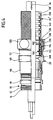
- an inventive Cable arrangement comprising a cable gland with a Cable and a cable protection hose, shown in Fig. 4, is in contrast to the first embodiment of the cable protection hose 92 not formed from a corrugated hose 98 ', which over the entire longitudinal extent 94 is electrically conductive, but for example from one Hose made of non-conductive electrical material or a Hose made of non-electrically connected Segments.
- the cable protection hose includes 92 'on an outer side 138 of the corrugated hose 98' additionally arranged metal mesh 140, which over the total extension of the cable protection hose 92 'in the Longitudinal direction 94 extends and also through the end grommet 100 between the outer jacket 112 and the outer side 138 of the Corrugated hose 98 'pinched and thus electrically through the end spout 100 is contacted, so that in turn electrical contact between the metal mesh 140 and the End grommet 100 and thus also the contact element 116 thereof exists and the contact is made in the same way can, the cable gland is identical as in the first embodiment.
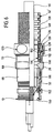
- FIG. 5 shown in FIG. 5 are the parts that match those of the first and the second embodiment are identical to the same Provide reference numerals so that with regard to their Description on the explanations to the previous Embodiments can be referenced.
- this shield contact element 152 has a carrier part 154, of which Contact springs 156 radially in the direction of the longitudinal axis 42 protrude and have an end bend 158, with which contact a screen 160 of the cable 56, which is covered by an outer jacket 162 in the cable 56 and encloses an inner conductor region 164 of the cable 56.
- the cable shield 160 is preferably in the form of a Metal mesh is formed and is used for contacting the shield contact element 152 by removing the outer jacket 162 exposed.
- the receptacle 150 for the shield contact element 152 is limited the interior 62 and extends from the Housing-side opening 64 in the form of a to the longitudinal axis 42 cylindrical surface 170 to an undercut 172, which is preferably in the area of the key surface section 18 lies and on its side facing the opening 64 flange surface extending approximately perpendicular to the longitudinal axis 42 174 has.
- the carrier part 154 in turn has an annular shape to the Longitudinal axis 42 bent flat material strips 180, which has an outer surface 182 on the cylinder surface 170 abuts and guided by this in the direction of the longitudinal axis 42 is. Furthermore, latching elements 184, for example, are on the carrier part 154 in the form of outwardly bent claws, which with the carrier part inserted into the receptacle 150 154 engage in the undercut 172 and with their Ends 186 facing opening 64 on flange surface 174 rest and thus the support member 154 against movement in Secure direction of opening 64.
- the carrier part 154 as a whole is through the opening 64 can be inserted into the socket 10, the Claws 184 due to their training in the form of bends resilient from the flat material of the carrier part 154 are movable so that they are approximately flush with the flat material of the carrier part 154 can be aligned in order to be inserted of the carrier part 154 from the opening 64 in the Do not hinder nozzle 10 until the claws 184 the Reach undercut 172, and then because of their Spring action jump radially outwards and into the undercut 172 in the manner already described intervention.
- the shield contact element 152 is also electrical conductive, so that there is an electrical connection between the cable shield 160 and the socket 10 manufactures.
- the carrier part 154 is for example slotted ring with a radial direction to the longitudinal axis 42 acting voltage trained so that a safe electrical contact between the support member 154 and the cylindrical surface 170 of the receptacle 150 is formed.
- the resilient claws 184 also cause in particular with their ends 186 a mechanical contact with high punctiform surface pressure, so that this too a good electrical connection between the nozzle 10 and the shield contact element 152 can be produced.
- the corrugated hose 98 is made of metal, however, a helix-like spiral and interlocking Double bead manufactured and therefore particularly good in the longitudinal direction 94 compressible, however, that is Shielding effect limited, so that this is preferably in Can be used in connection with the third embodiment is.
- a fourth embodiment shown in Fig. 6, are those parts with those of the previous embodiments are identical, with the same reference numerals provided so that with regard to the description of the same in full on the explanations of the first exemplary embodiments Can be referenced.
- the cable protection hose 92 ' is the same Formed like in the second embodiment, while the nozzle 10 in the same way as in the third Embodiment provided with a shield contact element 152 is arranged in the receptacle 150 of the nozzle 10 is.
Abstract
Description
Die Erfindung betrifft eine Kabelverschraubung umfassend einen mit einem auf einem definierten elektrischen Potential liegenden Bauteil, insbesondere einem Gehäuse, verbindbaren Stutzen, eine in ein Inneres des Stutzens einsetzbare Dichtung sowie ein mit dem Stutzen verschraubbares Druckelement, welches auf die Dichtung im Sinne eines Anlegens derselben an einen Mantel eines durch die Kabelverschraubung hindurchgeführten Kabels wirkt.The invention relates to a cable gland comprising one with a defined electrical potential lying component, in particular a housing, connectable Nozzle, one that can be inserted into an interior of the nozzle Seal and a pressure element that can be screwed to the socket, which on the seal in the sense of an application the same to a jacket through the cable gland passed cable acts.
Derartige Kabelverschraubungen sind aus dem Stand der Technik bekannt. Bei diesen Kabelverschraubungen soll das Kabel dicht abgeschlossen mit dem Bauteil, in welches der Stutzen einschraubbar ist, verbunden werden.Such cable glands are from the prior art known. With these cable glands, the cable should be tight completed with the component into which the nozzle can be screwed is to be connected.
Derartige Kabelverschraubungen werden vielfach unter ungünstigen Umgebungsbedingungen eingesetzt, welche eine Abdichtung zwischen dem Kabel und der Kabelverschraubung erforderlich machen.Such cable glands are often under unfavorable environmental conditions, which a Sealing between the cable and the cable gland make necessary.
Bei derartigen Einsatzfällen besteht das Problem, daß die Kabelverschraubung und das Kabel optimal gegen Umgebungseinflüsse geschützt werden sollten.In such cases, there is the problem that the Cable gland and the cable optimally against environmental influences should be protected.
Die Aufgabe der Erfindung besteht daher darin, eine Kabelverschraubung und eine Kabelanordnung zu schaffen, die einen optimalen und möglichst geschützten Einbau eines Kabels ermöglicht. The object of the invention is therefore a cable gland and to create a cable assembly that one optimal and as protected as possible installation of a cable enables.
Diese Aufgabe wird bei einer Kabelverschraubung der eingangs beschriebenen Art erfindungsgemäß dadurch gelöst, daß auf einer dem Stutzen gegenüberliegenden Seite des Druckelements eine Aufnahme vorgesehen ist, in welche ein Ende eines den Mantel des Kabels umgebenden und über seine Länge elektrisch leitend ausgebildeten Kabelschutzschlauchs einsetzbar ist, daß ein mit dem Druckelement verbindbares Klemmelement vorgesehen ist, mit welchem das Ende des Kabelschutzschlauchs mechanisch und elektrisch leitend mit dem Druckelement verbindbar ist und daß das Druckelement mit dem Stutzen und der Stutzen mit dem Bauteil elektrisch leitend verbunden sind.This task is done with a cable gland at the beginning described type according to the invention solved in that a side of the pressure element opposite the neck a receptacle is provided in which one end of the Sheath of the cable surrounding and electrical over its length conductive cable protection hose can be used, that a connectable to the pressure element clamping element is provided with which the end of the cable protection conduit connectable mechanically and electrically to the pressure element is and that the pressure element with the nozzle and the Stubs are electrically connected to the component.
Der Vorteil der erfindungsgemäßen Lösung ist darin zu sehen, daß einerseits der Kabelschutzschlauch einen mechanischen Schutz für das Kabel liefert und außerdem der Kabelschutzschlauch zusätzlich noch eine elektrische Abschirmung für das Kabel darstellt, wobei durch das elektrische Verbinden des Kabelschutzschlauchs letztlich mit dem Bauteil eine hervorragende und insbesondere lückenlose Abschirmung des Kabels auch im Bereich der Kabelverschraubung gewährleistet ist.The advantage of the solution according to the invention can be seen in that on the one hand the cable protection hose has a mechanical Protection for the cable provides and also the cable protection hose additionally an electrical shield for the Cable represents, by the electrical connection of the Cable protection hose ultimately with the component an excellent and in particular complete shielding of the cable is also guaranteed in the area of the cable gland.
Gleichzeitig wirkt sich die Abdichtung zwischen dem Kabel und dem Stutzen insoweit vorteilhaft aus, als selbst bei in den Kabelschutzschlauch eindringendem Schmutz oder Wasser dieses nicht in das Bauteil, insbesondere das Gehäuse, gelangen kann und umgekehrt auch keine Verunreinigungen vom Gehäuse in den Kabelschutzschlauch eintreten können.At the same time, the seal between the cable and the nozzle advantageous to the extent that even in the Cable protection hose penetrating dirt or water this cannot get into the component, especially the housing and vice versa also no contamination from the housing in the Cable protection hose can enter.
Darüber hinaus hat die erfindungsgemäße Lösung noch den großen Vorteil, daß sie einfach montierbar ist, da der Kabelschutzschlauch beispielsweise dann noch über das Kabel führbar ist, wenn dieses mit einem Ende angeschlossen und auch bereits in dem Stutzen mittels des Druckelements und der Dichtung fixiert ist.In addition, the solution according to the invention still has the great advantage that it is easy to install because of the cable protection hose for example then via the cable is feasible if this is connected with one end and already in the nozzle by means of the pressure element and Seal is fixed.
Eine besonders günstige Lösung der erfindungsgemäßen Kabelverschraubung sieht vor, daß die Aufnahme als Aufnahme für eine Endtülle des Kabelschutzschlauchs ausgebildet ist. Das Vorsehen einer Endtülle des Kabelschutzschlauchs schafft die Möglichkeit, diesen einerseits mechanisch stabil und andererseits mit gutem elektrischem Kontakt am Druckelement zu fixieren. Dabei hat die Endtülle außerdem den großen Vorteil, daß diese fest auf dem Kabelschutzschlauch sitzt und somit insbesondere vorkonfektioniert bereits mit dem Kabelschutzschlauch geliefert werden kann.A particularly cheap solution of the cable gland according to the invention stipulates that the recording as a recording for an end grommet of the cable protection conduit is formed. The Providing an end grommet for the cable protection conduit creates the Possibility of this mechanically stable on the one hand and on the other hand with good electrical contact on the pressure element fix. The end spout also has the great advantage that this sits firmly on the cable protection conduit and thus especially pre-assembled with the cable protection hose can be delivered.
Vorzugsweise ist dabei die Aufnahme so ausgebildet, daß sie eine sich in radialer Richtung zu einer Längsachse der Kabelverschraubung erstreckende Anlagefläche für ein Anlageelement der Endtülle aufweist.Preferably, the receptacle is designed so that it one in the radial direction to a longitudinal axis of the cable gland extending contact surface for a contact element has the end spout.
Eine besonders günstige Ausbildung der Anlagefläche sieht dabei vor, daß die Anlagefläche sich in Richtung einer Einführöffnung der Aufnahme konisch erweitert. Eine derartige Anlagefläche hat den Vorteil, daß damit auch bei unterschiedlichen Toleranzen in einfacher Weise eine sichere und zuverlässige Fixierung des Anlageelements an der Aufnahme möglich ist.A particularly favorable design of the contact surface provides doing so that the contact surface is in the direction of an insertion opening the taper expanded. Such Contact surface has the advantage that it can be used even with different Tolerances in a simple way a safe and reliable Fixation of the contact element on the holder possible is.
Eine besonders sichere Fixierung des Anlageelements an der Anlagefläche ist insbesondere dann möglich, wenn das Anlageelement eine ebenfalls konisch geformte und der Anlagefläche zugewandten Oberfläche aufweist. Der Konuswinkel der Anlagefläche und der Konuswinkel der Oberfläche können dabei identisch sein.A particularly secure fixation of the contact element on the Contact surface is particularly possible if the contact element a also conical and the contact surface facing surface. The cone angle of the contact surface and the cone angle of the surface can be identical.
Es ist aber auch vorteilhaft, wenn die Konuswinkel zwischen den beiden unterschiedlich sind, um ein näherungsweise linienförmiges Anliegen der beiden aneinander zu erzielen. Eine besonders günstige Lösung sieht vor, daß der Konuswinkel der Oberfläche des Anlageelements kleiner ist als der Konuswinkel der Anlagefläche, wobei vorteilhafterweise dieser Konuswinkel geringfügig kleiner ausgebildet ist als der der Anlagefläche.But it is also advantageous if the cone angle between the two are different to approximate one to achieve linear contact between the two. A particularly favorable solution provides that the cone angle the surface of the contact element is smaller than the cone angle the contact surface, advantageously this Cone angle is made slightly smaller than that of the Contact surface.
Eine besonders günstige Lösung sieht vor, daß das Anlageelement durch einen mit seinen Ringflächen parallel zu einem Konus verlaufenden und an die Endtülle angeformten Ring gebildet ist.A particularly favorable solution provides that the contact element through one with its ring faces parallel to one Conical ring formed on the end grommet is formed.
Hinsichtlich der Ausbildung der elektrisch leitenden Verbindung zwischen dem Kabelschutzschlauch und dem Druckelement wurden bislang keine näheren Angaben gemacht. Beispielsweise wäre es möglich, ein separates elektrisches Verbindungselement zwischen dem Kabelschutzschlauch und dem Druckelement vorzusehen. Eine besonders günstige Lösung sieht vor, daß die elektrisch leitende Verbindung zwischen dem Kabelschutzschlauch und dem Druckelement über einen elektrischen Kontakt zwischen der Endtülle und dem Druckelement erfolgt, wobei die Endtülle elektrisch leitend mit dem in Längsrichtung des Kabelschutzschlauchs sich erstreckenden elektrisch leitenden Teil verbunden ist. With regard to the formation of the electrically conductive connection between the cable protection hose and the pressure element no further details have so far been given. For example it would be possible to have a separate electrical connector between the cable protection hose and the pressure element to provide. A particularly favorable solution provides that the electrically conductive connection between the cable protection conduit and the pressure element via an electrical contact between the end grommet and the pressure element, the End sleeve electrically conductive with the in the longitudinal direction of the Cable protection hose extending electrically conductive Part is connected.
Die elektrisch leitende Verbindung kann dabei auf unterschiedlichste Art und Weise zustande kommen. Beispielsweise ist es denkbar, daß die Endtülle mit Kontaktfedern versehen ist, welche an der Aufnahme anliegen und einen ausreichend guten Kontakt zwischen der Endtülle und dem Druckelement vermitteln.The electrically conductive connection can be very different Way come about. For example it is conceivable that the end grommet be provided with contact springs which one is close to the admission and one is sufficient Provide good contact between the end grommet and the pressure element.
Eine besonders günstige Lösung sieht vor, daß die elektrische Verbindung zwischen der Endtülle und dem Druckelement über eine im wesentlichen linienförmige Anlage der beiden aneinander erfolgt. Das Vorsehen einer linienförmigen Anlage zur Herstellung der Verbindung zwischen den beiden hat den Vorteil, daß damit eine möglichst hohe Flächenpressung und somit ein möglichst guter elektrischer Kontakt zwischen diesen beiden mit möglichst geringem Kontaktwiderstand erzielbar ist.A particularly favorable solution provides that the electrical Connection between the end grommet and the pressure element via an essentially linear arrangement of the two against each other he follows. The provision of a linear system for Making the connection between the two has the advantage that with it the highest possible surface pressure and thus the best possible electrical contact between them both can be achieved with the lowest possible contact resistance is.
Eine besonders günstige Lösung sieht vor, daß die Endtülle an einer Kante der Aufnahme anlegbar ist, da es besonders einfach ist, für die im wesentlichen linienförmige Anlage zwischen den beiden erforderliche Kante in die Aufnahme einzuformen oder an diese anzuformen, während das Vorsehen einer Kante im Bereich der Endtülle selbst mit mehr Aufwand verbunden ist.A particularly cheap solution provides that the end grommet an edge of the receptacle can be put on because it is particularly simple is for the essentially linear system between the two required edge in the receptacle to mold or mold to this while providing an edge in the area of the end grommet itself with more effort connected is.
Besonders günstig ist es hierbei, wenn die elektrisch leitende Verbindung zwischen der Endtülle und dem Druckelement über das an einer Kante auf einer Seite der Anlagefläche anliegende Anlageelement erfolgt.It is particularly favorable here if the electrical conductive connection between the end grommet and the pressure element over that on an edge on one side of the contact surface adjacent contact element takes place.
Hinsichtlich des im Zusammenhang mit der erfindungsgemäßen Lösung vorgesehenen Klemmelements wurden keine näheren Angaben gemacht. So sieht ein vorteilhaftes Ausführungsbeispiel vor, daß das Klemmelement eine Überwurfmutter umfaßt, welche auf das Druckelement aufschraubbar ist, damit einer derartigen Überwurfmutter, in gleicher Weise wie beim Druckelement, einerseits große Kräfte zum Fixieren und Klemmen des Kabelschutzschlauchs und der Endtülle erreichbar sind und andererseits eine einfache Montage möglich ist.With regard to in connection with the invention Solution provided clamping element were no closer Information provided. So looks an advantageous one Embodiment before that the clamping element is a union nut comprises which can be screwed onto the pressure element, with such a cap nut, in the same way as with the pressure element, on the one hand large forces for fixing and The cable protection hose and the end grommet can be clamped are and on the other hand simple assembly is possible.
Um mit einem derart ausgebildeten Klemmelement die Endtülle gut in der Aufnahme zu fixieren, ist vorzugsweise vorgesehen, daß das Klemmelement ein beispielsweise von der Überwurfmutter beaufschlagtes Druckteil umfaßt, welches auf das Anlageelement der Endtülle wirkt. Mit einem derartigen insbesondere als Druckring ausgebildeten Druckteil ist eine besonders sichere und dauerhafte Beaufschlagung des Anlageelements in Richtung der Anlagefläche gewährleistet, da der Druckring über die gesamte Erstreckung des Anlageelements in Azimutalrichtung auf das Anlageelement wirkt.To the end grommet with such a clamping element to fix well in the receptacle is preferably provided that the clamping element, for example, from the union nut acted upon pressure part, which on the Contact element of the end grommet works. With such a especially designed as a pressure ring is a pressure part particularly safe and permanent loading of the contact element guaranteed in the direction of the contact surface, since the Pressure ring over the entire extent of the contact element in Azimuth direction acts on the contact element.
Eine besonders vorteilhafte Lösung sieht dabei vor, daß das Druckteil elastisch ausgebildet ist, so daß sich dieses beispielsweise durch die Überwurfmutter vorspannen läßt, um ständig die Endtülle an dem Druckelement kraftbeaufschlagt in Anlage zu halten.A particularly advantageous solution provides that the Pressure part is designed to be elastic, so that this is for example can be biased by the union nut to constantly pressurized the end grommet on the pressure element Keep plant.
Eine besonders sichere Fixierung der Endtülle mit dem Anlageelement ist dann möglich, wenn das Druckteil mit einem Druckkeil zwischen einer Außenseite des Kabelschutzschlauchs und dem Anlageelement der Endtülle eingreift und somit eine im wesentlichen zentrierte Fixierung des Kabelschutzschlauchs mit der Endtülle an der erfindungsgemäßen Kabelverschraubung gewährleistet. A particularly secure fixation of the end grommet with the contact element is possible if the pressure part with a pressure wedge between an outside of the cable protection conduit and engages the contact element of the end grommet and thus an im essentially centered fixing of the cable protection conduit with the end grommet on the cable gland according to the invention guaranteed.
Bei den bislang beschriebenen Varianten der erfindungsgemäßen Lösung wird stets davon ausgegangen, daß eine Abschirmung über den Kabelschutzschlauch erfolgt. Dies ist in einer Vielzahl von Fällen ausreichend. In besonders ungünstigen Umgebungen ist jedoch vorgesehen, daß in dem Stutzen ein Schirmkontaktelement angeordnet ist, welches in elektrischem Kontakt mit dem Stutzen steht und mittels mindestens eines in Richtung des durchgeführten Kabels reichenden Kontaktbügels einen einen Innenleiterbereich des Kabels umschließenden, freigelegten Kabelschirm kontaktiert. Die Vorteile dieser Lösung gehen jedoch über die Vorteile einer bloßen doppelten Abschirmung des Kabels hinaus, da einerseits der Kabelschutzschlauch bereits eine Abschirmung liefert, die sich unmittelbar über das Druckelement um den Stutzen bis zu dem Bauteil oder Gehäuse fortsetzt und in dieser Abschirmung noch eine zusätzliche Abschirmung vorgesehen ist, welche einen in das Kabel integrierten Kabelschirm ausnützt, wobei diese beiden, bereits über die Kabelverschraubung direkt elektrisch miteinander in Verbindung stehenden Abschirmungen den Vorteil haben, daß sich in Längsrichtung des Kabelschutzschlauchs induzierte Ströme unmittelbar über den Kabelschirm kompensieren lassen und somit letztlich auf all die Leitungen, die innerhalb des Kabelschirms liegen, keinerlei Einfluß haben können. Das heißt, daß die über die Kabelverschraubung hergestellte elektrische Verbindung zwischen dem Kabelschutzschlauch und dem in dem Kabel integrierten Kabelschirm eine optimale Unterdrückung und Abschirmung gegenüber Einstreuungen liefert.In the variants of the invention described so far Solution is always assumed to be a shield via the cable protection hose. This is in a variety of cases sufficient. In particularly unfavorable environments however, it is contemplated that a Shield contact element is arranged, which in electrical There is contact with the nozzle and by means of at least one in Direction of the contact bracket reaching through the cable an inner conductor area of the cable, exposed cable shield contacted. The advantages of this However, solution go beyond the benefits of a mere double Shielding the cable, because on the one hand the cable protection hose already provides a shield that is immediate over the pressure element around the nozzle up to the component or housing and another in this shield additional shielding is provided, which one in the Cable integrated cable shield exploits, these two, already electrically with each other via the cable gland related shields the advantage have that in the longitudinal direction of the cable protection conduit Compensate induced currents directly via the cable shield and ultimately on all the lines that lie within the cable shield, have no influence can. This means that the one produced via the cable gland electrical connection between the cable protection conduit and the cable shield integrated in the cable optimal suppression and shielding from Interferences.
Eine besonders günstige Lösung sieht vor, daß der Kontaktbügel, vorzugsweise in einer ungefähr parallel zur Längsachse der Kabelverschraubung verlaufenden Ebene, federnd bewegbar ist, wobei durch dieses federnde Bewegen eine sichere Kontaktierung des Kabelschirms durch den Kabelbügel möglich ist.A particularly favorable solution provides that the contact bracket, preferably in an approximately parallel to the longitudinal axis the level of the cable gland, resiliently movable is, with this resilient movement a safe The cable shield can be contacted through the cable bracket is.
Eine besonders günstige Lösung sieht dabei vor, daß das Schirmkontaktelement mehrere Kontaktbügel aufweist.A particularly cheap solution provides that Shield contact element has several contact brackets.
Um das Schirmkontaktelement günstig am Stutzen fixieren zu können, ist vorgesehen, daß das Schirmkontaktelement ein Trägerteil aufweist, an welchem die Kontaktbügel gehalten sind.To fix the shield contact element cheaply on the socket can, it is provided that the shield contact element Has carrier part on which the contact bracket is held are.
Besonders günstig läßt sich das Schirmkontaktelement dann an dem Stutzen fixieren, wenn das Schirmkontaktelement in einer Aufnahme des Stutzens sitzt und damit in einfacher Art und Weise sicher am Stutzen gehalten werden kann.The shield contact element can then be particularly inexpensive fix the socket if the shield contact element in a Recording the nozzle sits and thus in a simple manner and Way can be held securely on the neck.
Besonders günstig ist es dabei, wenn das Trägerteil relativ zum Stutzen fixiert angeordnet ist und somit im wesentlichen an dem Stutzen festgelegt ist.It is particularly favorable if the carrier part is relative is arranged fixed to the neck and thus essentially is attached to the nozzle.
Besonders günstig ist es hierbei, wenn das Trägerteil mit einer Außenfläche in Richtung der Längsachse der Kabelverschraubung in der Aufnahme geführt ist.It is particularly favorable here if the carrier part also an outer surface in the direction of the longitudinal axis of the cable gland is recorded.
Ferner ist es vorteilhaft, wenn zum Fixieren des Schirmkontaktelements in der Aufnahme vorgesehen ist, daß dieses mittels Rastelementen in Richtung der Längsachse fixiert ist.It is also advantageous if to fix the shield contact element it is provided in the recording that this is fixed in the direction of the longitudinal axis by means of locking elements.
Eine besonders günstige Lösung sieht dabei vor, daß das Schirmkontaktelement mittels mindestens einer in eine Ausnehmung der Aufnahme eingreifenden Kralle in Richtung der Längsachse fixiert ist. A particularly cheap solution provides that Shield contact element by means of at least one in a recess the claw engaging in the direction of the Longitudinal axis is fixed.
Um das Schirmkontaktelement einfach montieren zu können, ist vorteilhafterweise vorgesehen, daß das Schirmkontaktelement von einer dem Druckelement gegenüberliegenden Seite des Stutzens in die Aufnahme einschiebbar ist. Diese Seite ist üblicherweise die Gehäuseseite des Stutzens.In order to be able to easily mount the shield contact element advantageously provided that the shield contact element from a side of the pressure element opposite the Nozzle can be inserted into the receptacle. This page is usually the housing side of the nozzle.
Vorzugsweise schließt sich dabei die Aufnahme an eine dem Druckelement gegenüberliegende Öffnung des Stutzens an, so daß das Schirmkontaktelement möglichst dicht bei dem Bauteil sitzt, in welches der Stutzen einschraubbar ist.Preferably, the receptacle connects to one of the Pressure element opposite opening of the nozzle, so that the shield contact element as close as possible to the component sits, in which the nozzle can be screwed.
Die Erfindung betrifft jedoch nicht nur eine Kabelverschraubung, sondern auch eine Kabelanordnung, umfassend eine Kabelverschraubung und ein in dieser gehaltenes Kabel, wobei erfindungsgemäß die Kabelanordnung mit einem Kabelschutzschlauch versehen ist und außerdem entsprechend den vorstehend beschriebenen Ausführungsbeispielen ausgebildet ist. Der Vorteil dieser Lösung ist in der bereits vorstehend diskutierten Möglichkeit einer vorteilhaften Abschirmung des Kabels zu sehen.However, the invention relates not only to a cable gland, but also a cable assembly comprising one Cable gland and a cable held in this, wherein according to the invention the cable arrangement with a cable protection hose is provided and also according to the above described embodiments is formed. The advantage of this solution is already in the above discussed possibility of an advantageous shielding of the Cable.
Besonders günstig ist es hierbei, wenn der Kabelschutzschlauch in seiner Längsrichtung variabel, das heißt entweder elastisch dehnbar oder stauchbar ist, da damit eine Montage des Kabelschutzschlauchs selbst bei mit beiden Enden in die Kabelverschraubungen fixiertem Kabel möglich ist.It is particularly favorable here if the cable protection hose variable in its longitudinal direction, that is either is elastically stretchable or compressible, since it is an assembly of the cable protection conduit itself with both ends in the Cable glands fixed cable is possible.
Hinsichtlich der leitfähigen Ausbildung des Kabelschutzschlauchs über seine Länge wurden bislang keine näheren Angaben gemacht. So sieht eine vorteilhafte Lösung vor, daß der Kabelschutzschlauch in dessen Längsrichtung leitfähiges Element aufweist, wobei diese Lösung voraussetzt, daß dieses Element auch direkt in der Längsrichtung leitfähig ist und somit parallel zu dieser Richtung fließende Ströme in diesem auftreten können. Diese Lösung ist die günstigste Lösung, da sie eine optimale Abschirmung gewährleistet.With regard to the conductive design of the cable protection conduit So far there have been no closer to its length Information provided. So an advantageous solution provides that the cable protection conduit is conductive in its longitudinal direction Element has, this solution requires that this Element is also conductive directly in the longitudinal direction and thus currents flowing parallel to this direction in this may occur. This solution is the cheapest solution there it ensures optimal shielding.
Es ist jedoch aber auch aus vielerlei Gründen vorteilhaft, die Kabelanordnung so auszubilden, daß der Kabelschutzschlauch ein nur in einer Spiralrichtung elektrisch leitendes Element umfaßt, da ein derartiges elektrisch leitendes Element, insbesondere mit Längenvariabilität besonders einfach und günstig herstellbar ist und insbesondere in Verbindung mit einem ohnehin in dem Kabel vorgesehenen Kabelschirm eine ausreichende zusätzliche Schirmwirkung entfaltet.However, it is also advantageous for a number of reasons form the cable assembly so that the cable protection hose one that is only electrically conductive in one spiral direction Element comprises such an electrically conductive Element, especially with variable length is easy and inexpensive to manufacture and especially in Connection to a cable shield provided in the cable anyway a sufficient additional shielding effect develops.
Zum Fixieren des Kabelschutzschlauchs in der erfindungsgemäßen Kabelverschraubung ist vorzugsweise vorgesehen, daß der Kabelschutzschlauch mit einer Endtülle versehen ist.For fixing the cable protection conduit in the invention Cable gland is preferably provided that the cable protection hose is provided with an end grommet.
Diese Endtülle kann in unterschiedlichster Art und Weise ausgebildet sein. Eine vorteilhafte Lösung sieht vor, daß die Endtülle einen Innenmantel für den Kabelschutzschlauch aufweist und somit mit diesem im Inneren des Kabelschutzschlauchs an diesem anliegt.This end grommet can be designed in a wide variety of ways be. An advantageous solution provides that the End sleeve has an inner jacket for the cable protection conduit and thus with this inside the cable protection conduit on this.
Vorzugsweise ist die Endtülle mit dem Innenmantel an dem Kabelschutzschlauch fixiert. Dabei wäre es denkbar, die Endtülle mit dem Kabelschutzschlauch zu verkleben, zu verlöten oder über formschlüssige Elemente zu verbinden. Eine besonders günstige formschlüssige Verbindung sieht vor, daß die Endtülle über in Sicken des Kabelschutzschlauchs eingreifende eigene Sicken an diesem fixierbar ist. Preferably, the end sleeve with the inner jacket on the Cable protection hose fixed. It would be conceivable that To glue the end grommet with the cable protection hose solder or connect using form-fitting elements. A particularly favorable positive connection provides that the end grommet engaging in the beads of the cable protection conduit own beads can be fixed on this.
Ferner ist vorteilhafterweise vorgesehen, daß die Endtülle einen Außenmantel für den Kabelschutzschlauch aufweist.It is also advantageously provided that the end grommet has an outer jacket for the cable protection conduit.
Zur Fixierung der Endtülle in der Aufnahme der erfindungsgemäßen Kabelverschraubung ist vorzugsweise vorgesehen, daß die Endtülle ein sich vom Kabelschutzschlauch aus nach außen erstreckendes Anlageelement aufweist, welches dann an die Anlagefläche der Aufnahme anlegbar ist.To fix the end grommet in the receptacle of the invention Cable gland is preferably provided that the end grommet extends from the cable protection hose to the outside extending contact element, which then to the Contact surface of the recording can be created.
Eine zweckmäßige Ausgestaltung eines derartigen Aufnahmeelements sieht vor, daß dieses als parallel zu einer Konusfläche verlaufender Ring ausgebildet ist.An expedient embodiment of such a receiving element stipulates that this is parallel to a conical surface extending ring is formed.
Weitere Merkmale und Vorteile der Erfindung sind Gegenstand der nachfolgenden Beschreibung sowie der zeichnerischen Darstellung einiger Ausführungsbeispiele.Other features and advantages of the invention are the subject the following description and the graphic Representation of some embodiments.
In der Zeichnung zeigen:
- Fig. 1
- eine halbseitig geschnittene, halbseitig vollständig gezeichnete Seitenansicht eines ersten Ausführungsbeispiels einer erfindungsgemäßen Kabelanordnung mit Kabelverschraubung;
- Fig. 2
- eine vergrößerte ausschnittsweise Darstellung eines Bereichs mit einem Dichtungsträger und einer Druckmutter;
- Fig. 3
- eine vergrößerte Darstellung eines Bereichs mit einer Aufnahme für ein Ende des Kabelschutzschlauchs;
- Fig. 4
- eine Seitenansicht ähnlich Fig. 1 eines zweiten Ausführungsbeispiels;
- Fig. 5
- eine Seitenansicht ähnliche Fig.1 eines dritten Ausführungsbeispiels und
- Fig. 6
- eine Seitenansicht ähnlich Fig. 1 eines vierten Ausführungsbeispiels.
- Fig. 1
- a half-sectioned, half-drawn side view of a first embodiment of a cable assembly according to the invention with cable gland;
- Fig. 2
- an enlarged fragmentary representation of an area with a seal carrier and a pressure nut;
- Fig. 3
- an enlarged view of an area with a receptacle for one end of the cable protection conduit;
- Fig. 4
- a side view similar to Figure 1 of a second embodiment.
- Fig. 5
- a side view similar Fig.1 of a third embodiment and
- Fig. 6
- a side view similar to FIG. 1 of a fourth embodiment.
Ein erstes Ausführungsbeispiel einer erfindungsgemäßen Kabelverschraubung,
dargestellt in Fig. 1, umfaßt einen als Ganzes
mit 10 bezeichneten und elektrisch leitend ausgebildeten
Stutzen, welcher einen zylindrischen Ansatz 12 mit einem
Außengewinde 14 aufweist, das in ein auf einem definierten
elektrischen Potential liegendes elektrisches Bauteil 16,
vorzugsweise eine Wand eines Gehäuses einschraubbar ist.A first embodiment of a cable gland according to the invention,
shown in Fig. 1 includes one as a whole
designated by 10 and electrically conductive
Stub, which has a
Der Stutzen 10 umfaßt ferner einen Schlüsselflächenabschnitt
18, welcher mit Schlüsselflächen 20 versehen ist und auf
einer einem gehäuseseitigen Ende 22 des zylindrischen
Ansatzes 12 gegenüberliegenden Seite unmittelbar im Anschluß
an den zylindrischen Ansatz 12 am Stutzen 10 angeordnet ist.The
Auf einer dem zylindrischen Ansatz 12 gegenüberliegenden
Seite des Schlüsselflächenabschnitts 18 des Stutzens 10 weist
dieser einen Abschnitt 24 auf, welcher ein Außengewinde 26
trägt.On a
Auf das Außengewinde 26 ist eine als Ganzes mit 28 bezeichnete
Druckmutter mit ihrem Innengewinde 30 aufschraubbar. On the
Der Abschnitt 24 dient zur Aufnahme eines als Ganzes mit 32
bezeichneten Dichtungsträgers, welcher mit einem Halteansatz
34 in den Abschnitt 24 eingreift und an einer inneren
Zylinderfläche 36 desselben in Richtung einer Längsachse 42
geführt ist. Ferner stützt sich der Dichtungsträger 32 mit
einer Flanschfläche 38 auf einer dem Schlüsselflächenabschnitt
18 abgewandten Flanschfläche 40 des Zylinderabschnitts
24 ab und ist dadurch in Richtung der Längsachse
42 der Kabelverschraubung gegen eine Verschiebung in Richtung
des Schlüsselflächenabschnitts 18 gesichert.
Der Dichtungsträger 32 umfaßt ferner einen Lamellenkorb 44,
der seinerseits eine ringförmig ausgebildete Dichtung 46 umschließt,
wobei die Dichtung 46 ferner durch einen inneren
Ansatz 48 des Dichtungsträgers 32 gegen eine Verschiebung in
Richtung der Längsachse 42 zum Schlüsselflächenabschnitt 18
hin fixierbar ist.The
Der Lamellenkorb 44 ist seinerseits durch eine radial nach
innen zur Längsachse 42 hin verlaufende Schrägfläche 50 der
Druckmutter 28 beaufschlagbar, welche bei zunehmendem Aufschrauben
der Druckmutter 28 auf das Außengewinde 26 die
Lamellen des Lamellenkorbs 44 zunehmend in Richtung der
Längsachse 42 deformiert und damit die in dem Lamellenkorb 44
aufgenommene Dichtung 46 ebenfalls so weit in Richtung der
Längsachse 42 bewegt, daß ein innerer Durchlaß 52 der
Dichtung 46 an einer Kabelaußenmantelfläche 54 eines Kabels
56 dichtend mit Pressung anlegbar ist, um einerseits eine
Abdichtung zwischen der Kabelverschraubung und dem Kabel 56
und andererseits eine Fixierung des Kabels 56 in Richtung der
Längsachse 42 zu erhalten. The
Das Kabel 56 verläuft dabei durch eine zur Längsachse 52
koaxiale Öffnung der Druckmutter 26, dann durch den Durchlaß
52 der Dichtung 46 hindurch und passiert dann einen inneren
Durchbruch 60 des Dichtungsträgers 32. Im Anschluß an den
Dichtungsträger 32 erstreckt sich das Kabel 56 durch einen
Innenraum 62 des Stutzens 10, welcher sich ausgehend vom
Zylinderabschnitt 24 durch den Schlüsselflächenabschnitt 18
und den zylindrischen Ansatz 12 bis zu einer gehäuseseitigen
Öffnung 64 des Stutzens ausdehnt.The
Die Druckmutter 28 weist vorzugsweise einen zylindrischen
Abschnitt 66 auf, welcher das Innengewinde 30 trägt und einen
sich daran anschließenden Schlüsselflächenabschnitt 68, der
einzelne Schlüsselflächen 70 aufweist und ungefähr im Bereich
der Öffnung 58 der Druckmutter 28 liegt.The
Auf einer dem zylindrischen Abschnitt 66 gegenüberliegenden
Seite des Schlüsselflächenabschnitts 60 trägt die Druckmutter
28 einen als Ganzes mit 72 bezeichneten zylindrischen
Abschnitt, der mit einem Außengewinde 74 versehen ist.On one opposite the
Der zylindrische Abschnitt 72 umschließt dabei eine als
Ganzes mit 76 bezeichnete Aufnahme, welche sich ausgehend von
einer endseitigen Öffnung 78 des zylindrischen Abschnitts 72,
die auf einer dem Schlüsselabschnitt 68 gegenüberliegenden
Seite des zylindrischen Abschnitts 72 liegt, in Richtung des
Schlüsselflächenabschnitts 68, im Innern der Druckmutter 28
erstreckt, und zwar bis zu einem trichterförmig auf die
Öffnung 58 zulaufenden und ein Einführen des Kabels 56
erleichternden Wandbereich 80. The
Die Aufnahme 76 weist dabei eine ausgehend von dem Wandbereich
80 sich in Richtung der endseitigen Öffnung 78
erstreckende und koaxial zur Längsachse 42 verlaufende
zylindrisch ausgebildete Wandfläche 82 auf, an welche sich
unter Ausbildung einer Kante 86 eine Anlagefläche 84
anschließt, die von der Kante 86 bis zur endseitigen Öffnung
78 verläuft und sich dabei von dem Radius der zylindrischen
Wandfläche 82 bis zur endseitigen Öffnung 78 konisch
erweitert, vorzugsweise entsprechend einer zur Längsachse 42
koaxial verlaufenden Konusfläche.The
Die endseitige Öffnung 78 stellt dabei eine Einführöffnung
für ein Ende 90 eines Kabelschutzschlauchs 92 dar, welcher
beispielsweise als längselastischer oder längsstauchbarer
Wellenschlauch 98 aus dünnem Metall ausgebildet und mit in
seiner Längsrichtung 94 mit aufeinanderfolgenden Sicken 96
versehen ist.The
Das Ende 90 des Kabelschutzschlauchs 92 ist dabei mit einer
mit 100 bezeichneten Endtülle versehen, welche mit einem
Innenmantel 102 im Bereich des Endes 90 in den Kabelschutzschlauch
92 eingreift und Mantelsicken 106 aufweist, die
ihrerseits in die Sicken 96 des Wellenschlauchs 98 eingreifen
und damit den Innenmantel 102 der Endtülle 100 fixieren.The
Ferner ist an den Innenmantel 102 eine zu einem Außenmantel
112 der Endtülle führende Umbiegung 108 angeformt, welche
eine Endkante 110 des Endes 90 des Kabelschutzschlauchs 92
umschließt. Der Außenmantel 112 liegt auf einer Außenseite
114 des Kabelschutzschlauchs 92 im Bereich des Endes 90 an
und erstreckt sich bis zu einem vorzugsweise ringförmig ausgebildeten
Anlageelement 116, das konisch zum Außenmantel 112
und von dem Kabelschutzschlauch 92 radial nach außen weg verläuft.
Vorzugsweise bildet das Anlageelement 116 einen
konisch um den Außenmantel 112 verlaufenden Ring, welcher
sich ausgehend von dem Außenmantel 112 und in Richtung von
der Umbiegung 108 weg konisch erweitert.Furthermore, on the
Vorzugsweise ist das Anlageelement 116 so geformt, daß es so
weit über den Außenmantel 112 in radialer Richtung übersteht,
daß dieses an der Anlagefläche 84 anlegbar ist und zwar insbesondere
im Bereich einer der Kante 86, mit welcher die
Anlagefläche 84 in die zylindrische Wandfläche 82 übergeht.Preferably, the
Die Endtülle 100 ist elektrisch leitend mit dem Wellenschlauch
98 verbunden, welcher ebenfalls in seiner Längsrichtung
94 über seine ganze Länge elektrisch leitend ist.The
Durch die Ausführung der Endtülle 100 aus elektrisch leitendem
Material oder Material mit einer elektrisch leitenden
Oberflächenveredelung, beispielsweise einer Verzinkung, ist
somit auch eine elektrische Verbindung zwischen der Endtülle
100 und der Druckmutter 28 mit dem zylindrischen Abschnitt
72, insbesondere der Anlagefläche 84 derselben herstellbar,
wobei vorzugsweise durch ein Anpressen des Anlageelements 116
an die Anlagefläche 84, vorzugsweise im Bereich der Kante 86
aufgrund einer zumindest teilweise linienförmigen Berührung
des Anlageelements 116 im Bereich der Kante 118 die für einen
guten elektrischen Kontakt erforderliche hohe Flächenpressung
erreichbar ist.By designing the
Um das Anlageelement 116 und somit auch die Endtülle 100 in
der Aufnahme 76 zu fixieren und andererseits den bereits
beschriebenen elektrischen Kontakt zwischen der
Anlagefläche 84 und/oder der Kante 86 und dem Anlageelement
116 herzustellen, ist ein als Ganzes mit 120 bezeichnetes
Klemmelement vorgesehen, welches eine Überwurfmutter 122
aufweist, die mit einem Innengewinde 124 auf das Außengewinde
74 des zylindrischen Ansatzes 72 aufschraubbar ist. Die Überwurfmutter
weist ferner einen radial über das Innengewinde
124 bis zu einer Durchtrittsöffnung 125 für das Kabel 56 nach
innen gezogenen Endflansch 126 auf, mit welchem ein vorzugsweise
ringförmiges Druckstück 128 beaufschlagbar ist, das
zwischen dem Endflansch 126 und dem Anlageelement 116
angeordnet ist.Around the
Das Druckelement 128 weist seinerseits einen inneren Durchbruch
130 auf, welcher von dem Kabelschutzschlauch 92 durchsetzt
ist und diesen auf seiner Außenseite 114 umgibt, und
außerdem eine Außenfläche 132, die konisch sich verjüngend in
Richtung auf ein das Anlageelement 116 beaufschlagendes Ende
134 verläuft, wobei der Konuswinkel so gewählt ist, daß das
Ende 134 zwischen dem Anlageelement 116 der Endtülle 100 und
der Außenseite 114 des Kabelschutzschlauchs 92 eingreift und
somit einerseits die gesamte Einheit aus Endtülle 100 und
Ende 90 des Kabelschutzschlauchs 92 in Richtung des
Schlüsselflächenabschnitts 68 beaufschlagt und andererseits
gleichzeitig das Anlageelement 116 gegen die Anlagefläche 84
und insbesondere die Kante 86 drückt, um den guten elektrischen
Kontakt zwischen diesem und der Druckmutter 28 herzustellen,
wobei die Druckmutter 28 im einfachsten Fall aus
elektrisch leitendem Material hergestellt ist.The
Vorzugsweise ist dabei das Druckelement 128 aus elastischem
Material ausgebildet, so daß die Überwurfmutter 120 so weit
auf die Druckmutter 128 aufschraubbar ist, bis das
Druckelement 128 aufgrund des elastischen Materials die
gewünschte Anpreßkraft zur Fixierung des Endes 90 des
Kabelschutzschlauchs 92 mit der Endtülle 100 erzeugt.The
Durch den elektrisch leitend ausgebildeten und elektrisch
leitend mit dem Bauteil 16 verbundenen Stutzen 10, die elektrisch
leitend ausgebildete und elektrisch leitend mit dem
Stutzen 10 verbundene Druckmutter 28, die Endtülle, die die
Druckmutter 28 und den Wellenschlauch 98 elektrisch leitend
miteinander verbindet, sowie den über seine gesamte
Erstreckung in Längsrichtung 94 elektrisch leitenden Wellenschlauch
98 ist eine umfassende elektrische Abschirmung des
Kabels 56 geschaffen, in einer erfindungsgemäßen Kabelanordnung,
umfassend die Kabelverschraubung, das Kabel 56 und
den Kabelschutzschlauch, gegeben.Due to the electrically conductive and electrical
Conductively connected to the
Bei einem zweiten Ausführungsbeispiel einer erfindungsgemäßen
Kabelanordnung, umfassend eine Kabelverschraubung mit einem
Kabel und einem Kabelschutzschlauch, dargestellt in Fig. 4,
ist im Gegensatz zum ersten Ausführungsbeispiel der Kabelschutzschlauch
92 nicht aus einem Wellenschlauch 98' ausgebildet,
welcher über die gesamte Längserstreckung 94
elektrisch leitend ist, sondern beispielsweise aus einem
Schlauch aus nichtleitendem elektrischem Material oder einem
Schlauch aus nicht elektrisch leitend miteinander verbundenen
Segmenten. Aus diesem Grund umfaßt der Kabelschutzschlauch
92' auf einer Außenseite 138 des Wellenschlauchs 98' ein
zusätzlich angeordnetes Metallgeflecht 140, welches über die
gesamte Erstreckung des Kabelschutzschlauchs 92' in der
Längsrichtung 94 verläuft und außerdem durch die Endtülle 100
zwischen dem Außenmantel 112 und der Außenseite 138 des
Wellenschlauchs 98' eingeklemmt und somit elektrisch durch
die Endtülle 100 kontaktiert ist, so daß wiederum ein
elektrischer Kontakt zwischen dem Metallgeflecht 140 und der
Endtülle 100 und somit auch dem Anlageelement 116 derselben
besteht und die Kontaktierung in gleicher Weise erfolgen
kann, wobei die Kabelverschraubung identisch ausgebildet ist
wie beim ersten Ausführungsbeispiel.In a second embodiment of an inventive
Cable arrangement, comprising a cable gland with a
Cable and a cable protection hose, shown in Fig. 4,
is in contrast to the first embodiment of the
Bei einem dritten Ausführungsbeispiel, dargestellt in Fig. 5 sind diejenigen Teile, die mit denen des ersten und des zweiten Ausführungsbeispiels identisch sind, mit denselben Bezugszeichen versehen, so daß hinsichtlich deren Beschreibung auf die Ausführungen zu den vorangehenden Ausführungsbeispielen Bezug genommen werden kann.In a third exemplary embodiment, shown in FIG. 5 are the parts that match those of the first and the second embodiment are identical to the same Provide reference numerals so that with regard to their Description on the explanations to the previous Embodiments can be referenced.
Im Gegensatz zu den ersten Ausführungsbeispielen ist in dem
zylindrischen Ansatz 12 des Stutzens 10 eine Aufnahme 150 für
ein Schirmkontaktelement 152 vorgesehen, wobei dieses Schirmkontaktelement
152 ein Trägerteil 154 aufweist, von welchem
Kontaktfedern 156 radial in Richtung der Längsachse 42
abstehen und eine endseitige Umbiegung 158 aufweisen, mit
welcher diese einen Schirm 160 des Kabels 56 kontaktieren,
welcher beim Kabel 56 von einem Außenmantel 162 überdeckt ist
und einen Innenleiterbereich 164 des Kabels 56 umschließt.
Der Kabelschirm 160 ist dabei vorzugsweise in Form eines
Metallgeflechts ausgebildet und wird zur Kontaktierung durch
das Schirmkontaktelement 152 durch Entfernung des Außenmantels
162 freigelegt.In contrast to the first exemplary embodiments
Die Aufnahme 150 für das Schirmkontaktelement 152 begrenzt
den Innenraum 62 und erstreckt sich ausgehend von der
gehäuseseitigen Öffnung 64 in Form einer zur Längsachse 42
zylindrischen Fläche 170 bis zu einer Hinterschneidung 172,
welche vorzugsweise im Bereich des Schlüsselflächenabschnitts
18 liegt und auf ihrer der Öffnung 64 zugewandten Seite eine
ungefähr senkrecht zur Längsachse 42 verlaufende Flanschfläche
174 aufweist.The
Das Trägerteil 154 weist seinerseits einen ringförmig zur die
Längsachse 42 gebogenen Flachmaterialstreifen 180 auf,
welcher mit einer Außenfläche 182 an der Zylinderfläche 170
anliegt und von dieser in Richtung der Längsachse 42 geführt
ist. Ferner sind an dem Trägerteil 154 Rastelemente 184, beispielsweise
in Form von nach außen gebogenen Krallen, vorgesehen,
welche bei in die Aufnahme 150 eingesetztem Trägerteil
154 in die Hinterschneidung 172 eingreifen und mit ihren der
Öffnung 64 zugewandten Enden 186 an der Flanschfläche 174
anliegen und damit das Trägerteil 154 gegen eine Bewegung in
Richtung der Öffnung 64 sichern.The
Vorzugsweise ist dabei das Trägerteil 154 als Ganzes durch
die Öffnung 64 in den Stutzen 10 einschiebbar, wobei die
Krallen 184 aufgrund ihrer Ausbildung in Form von Ausbiegungen
aus dem Flachmaterial des Trägerteils 154 federnd
bewegbar sind, so daß sie ungefähr fluchtend mit dem Flachmaterial
des Trägerteils 154 ausrichtbar sind, um ein Einschieben
des Trägerteils 154 von der Öffnung 64 her in den
Stutzen 10 nicht behindern, so lange, bis die Krallen 184 die
Hinterschneidung 172 erreichen, und dann aufgrund ihrer
Federwirkung radial nach außen springen und in die Hinterschneidung
172 in der bereits beschriebenen Art und Weise
eingreifen.Preferably, the
Erfindungsgemäß ist auch das Schirmkontaktelement 152 elektrisch
leitend ausgebildet, so daß es eine elektrische Verbindung
zwischen dem Kabelschirm 160 und dem Stutzen 10
herstellt. Hierzu ist das Trägerteil 154 als beispielsweise
geschlitzter Ring mit einer in radialer Richtung zur Längsachse
42 wirkenden Spannung ausgebildet, so daß eine sichere
elektrische Kontaktierung zwischen dem Trägerteil 154 und der
zylindrischen Fläche 170 der Aufnahme 150 entsteht.According to the invention, the
Ferner bewirken auch die federnd ausgebildeten Krallen 184,
insbesondere mit ihren Enden 186 einen mechanischen Kontakt
mit hoher punktförmiger Flächenpressung, so daß auch hierdurch
eine gute elektrische Verbindung zwischen dem Stutzen
10 und dem Schirmkontaktelement 152 herstellbar ist.Furthermore, the resilient claws 184 also cause
in particular with their ends 186 a mechanical contact
with high punctiform surface pressure, so that this too
a good electrical connection between the
Bei einem weiteren zeichnerisch nicht dargestellten Ausführungsbeispiel
ist der Wellenschlauch 98 zwar aus Metall,
jedoch eine helixähnlich gewendelten und dabei ineinandergreifenden
Doppelsicke hergestellt und daher besonders gut in
der Längsrichtung 94 stauchbar, allerdings ist dessen
Abschirmwirkung begrenzt, so daß dieser vorzugsweise im
Zusammenhang mit dem dritten Ausführungsbeispiel einsetzbar
ist.In a further embodiment, not shown in the drawing
the
Bei einem vierten Ausführungsbeispiel, dargestellt in Fig. 6, sind diejenigen Teile, die mit denen der voranstehenden Ausführungsbeispiele identisch sind, mit denselben Bezugszeichen versehen, so daß hinsichtlich der Beschreibung derselben vollinhaltlich auf die Ausführungen zu den ersten Ausführungsbeispielen Bezug genommen werden kann.In a fourth embodiment, shown in Fig. 6, are those parts with those of the previous embodiments are identical, with the same reference numerals provided so that with regard to the description of the same in full on the explanations of the first exemplary embodiments Can be referenced.
Insbesondere ist der Kabelschutzschlauch 92' in gleicher
Weise ausgebildet wie beim zweiten Ausführungsbeispiel,
während der Stutzen 10 in gleicher Weise wie bei dem dritten
Ausführungsbeispiel mit einem Schirmkontaktelement 152 versehen
ist, das in der Aufnahme 150 des Stutzens 10 angeordnet
ist.In particular, the cable protection hose 92 'is the same
Formed like in the second embodiment,
while the
Im übrigen sind die weiteren Teile in gleicher Weise ausgebildet wie beim ersten Ausführungsbeispiel, so daß auf die Ausführungen hierzu vollinhaltlich Bezug genommen werden kann.Otherwise, the other parts are designed in the same way as in the first embodiment, so that on the Full details of this are referred to can.
Claims (30)
dadurch gekennzeichnet,
daß auf einer dem Stutzen (10) gegenüberliegenden Seite des Druckelements (28) eine Aufnahme (76) vorgesehen ist, in welche ein Ende (90) eines den Mantel des Kabels (56) umgebenden und über seine Länge elektrisch leitend ausgebildeten Kabelschutzschlauchs (92) einsetzbar ist, daß ein mit dem Druckelement (28) verbindbares Klemmelement (120) vorgesehen ist, mit welchem das Ende (90) des Kabelschutzschlauchs (92) mechanisch und elektrisch leitend mit dem Druckelement (28) verbindbar ist und daß das Druckelement (28) mit dem Stutzen (10) und der Stutzen (10) mit dem Bauteil elektrisch leitend verbunden sind.Cable gland, comprising a connecting piece which can be connected to a defined electrical potential, in particular a housing, a seal which can be inserted into an interior of the connecting piece, and a pressure element which can be screwed to the connecting piece and which acts on the seal in the sense of applying the same to a jacket acts through the cable gland,
characterized,
that a receptacle (76) is provided on a side of the pressure element (28) opposite the connecting piece (10), into which an end (90) of a cable protection tube (92) which surrounds the jacket of the cable (56) and is electrically conductive over its length It can be used that a clamping element (120) which can be connected to the pressure element (28) is provided, by means of which the end (90) of the cable protection hose (92) can be connected to the pressure element (28) in a mechanically and electrically conductive manner and that the pressure element (28) with the connector (10) and the connector (10) are electrically connected to the component.
Applications Claiming Priority (2)
| Application Number | Priority Date | Filing Date | Title |
|---|---|---|---|
| DE19801145A DE19801145A1 (en) | 1998-01-14 | 1998-01-14 | Cable gland |
| DE19801145 | 1998-01-14 |
Publications (3)
| Publication Number | Publication Date |
|---|---|
| EP0930687A2 true EP0930687A2 (en) | 1999-07-21 |
| EP0930687A3 EP0930687A3 (en) | 2001-10-04 |
| EP0930687B1 EP0930687B1 (en) | 2007-01-03 |
Family
ID=7854586
Family Applications (1)
| Application Number | Title | Priority Date | Filing Date |
|---|---|---|---|
| EP99100268A Expired - Lifetime EP0930687B1 (en) | 1998-01-14 | 1999-01-08 | Cable gland |
Country Status (3)
| Country | Link |
|---|---|
| EP (1) | EP0930687B1 (en) |
| AT (1) | ATE350796T1 (en) |
| DE (2) | DE19801145A1 (en) |
Cited By (3)
| Publication number | Priority date | Publication date | Assignee | Title |
|---|---|---|---|---|
| FR2815483A1 (en) * | 2000-10-12 | 2002-04-19 | Fci France | Device of material recovery on a conductor |
| DE202009016477U1 (en) | 2009-11-25 | 2010-06-17 | Hidde, Axel R., Dr. | Electrical contacting device for cable and shielding |
| US8895878B2 (en) | 2012-07-20 | 2014-11-25 | Lapp Engineering & Co. | Cable feedthrough |
Families Citing this family (1)
| Publication number | Priority date | Publication date | Assignee | Title |
|---|---|---|---|---|
| US9312672B2 (en) | 2013-09-26 | 2016-04-12 | Panduit Corp. | Threaded sleeve compressed split cable gland |
Citations (6)
| Publication number | Priority date | Publication date | Assignee | Title |
|---|---|---|---|---|
| US4328392A (en) * | 1980-05-15 | 1982-05-04 | Automation Industries, Inc. | Welded-turn helical electrical conduit with electrically conductive grounding element |
| GB2214728A (en) * | 1988-01-20 | 1989-09-06 | C M P | Mounting cable gland without twisting cable |
| DE29611451U1 (en) * | 1996-07-01 | 1996-09-05 | Pma Elektro Ag | Connection element for connecting an electrically conductive shielding jacket with a screw connection |
| GB2312339A (en) * | 1996-03-25 | 1997-10-22 | Pma Elektro Ag | Connection element for screened conductors and cables |
| EP0803953A2 (en) * | 1996-04-19 | 1997-10-29 | U.I. Lapp Gmbh & Co. Kg | Cable gland |
| EP0871254A2 (en) * | 1997-04-07 | 1998-10-14 | Thomas & Betts Corporation | Rotationally unrestrained grounding coupling for external grounding of fittings |
-
1998
- 1998-01-14 DE DE19801145A patent/DE19801145A1/en not_active Ceased
-
1999
- 1999-01-08 EP EP99100268A patent/EP0930687B1/en not_active Expired - Lifetime
- 1999-01-08 AT AT99100268T patent/ATE350796T1/en active
- 1999-01-08 DE DE59914108T patent/DE59914108D1/en not_active Expired - Lifetime
Patent Citations (6)
| Publication number | Priority date | Publication date | Assignee | Title |
|---|---|---|---|---|
| US4328392A (en) * | 1980-05-15 | 1982-05-04 | Automation Industries, Inc. | Welded-turn helical electrical conduit with electrically conductive grounding element |
| GB2214728A (en) * | 1988-01-20 | 1989-09-06 | C M P | Mounting cable gland without twisting cable |
| GB2312339A (en) * | 1996-03-25 | 1997-10-22 | Pma Elektro Ag | Connection element for screened conductors and cables |
| EP0803953A2 (en) * | 1996-04-19 | 1997-10-29 | U.I. Lapp Gmbh & Co. Kg | Cable gland |
| DE29611451U1 (en) * | 1996-07-01 | 1996-09-05 | Pma Elektro Ag | Connection element for connecting an electrically conductive shielding jacket with a screw connection |
| EP0871254A2 (en) * | 1997-04-07 | 1998-10-14 | Thomas & Betts Corporation | Rotationally unrestrained grounding coupling for external grounding of fittings |
Cited By (4)
| Publication number | Priority date | Publication date | Assignee | Title |
|---|---|---|---|---|
| FR2815483A1 (en) * | 2000-10-12 | 2002-04-19 | Fci France | Device of material recovery on a conductor |
| DE202009016477U1 (en) | 2009-11-25 | 2010-06-17 | Hidde, Axel R., Dr. | Electrical contacting device for cable and shielding |
| DE102009055641A1 (en) | 2009-11-25 | 2011-05-26 | Hidde, Axel R., Dr. | Electrical contacting device for use in universal quick coupling piece for e.g. electrostatic shielding between electrical conductors, has contact sections with ends electrically connected with outer casing of inner conductor |
| US8895878B2 (en) | 2012-07-20 | 2014-11-25 | Lapp Engineering & Co. | Cable feedthrough |
Also Published As
| Publication number | Publication date |
|---|---|
| EP0930687A3 (en) | 2001-10-04 |
| DE59914108D1 (en) | 2007-02-15 |
| DE19801145A1 (en) | 1999-07-22 |
| EP0930687B1 (en) | 2007-01-03 |
| ATE350796T1 (en) | 2007-01-15 |
Similar Documents
| Publication | Publication Date | Title |
|---|---|---|
| DE102005016340B3 (en) | Cable feed through device, has cable feed through unit with fir tree shapely arranged lamellae at its outer side and rotation-symmetrically formed, where outer diameter of lamellae narrows in axial direction | |
| DE69734971T2 (en) | coaxial cable | |
| EP0598261B1 (en) | Cable gland for earthing or screening cable | |
| DE102009016227B4 (en) | Connector with a connected coaxial cable | |
| DE102015122471B4 (en) | Shielded connector assembly | |
| EP2532061B1 (en) | Electric device comprising a feedthrough of a cable through a housing wall | |
| DE19615602A1 (en) | Cable gland | |
| EP3022806B1 (en) | Assembly comprising a housing and a device for electrically contact a shielding of an electric cable | |
| BE1025878B1 (en) | Cable shield contacting device and electrical connector | |
| EP3574559B1 (en) | Cable bushing having shielding and sealing properties | |
| EP0583700A1 (en) | Crimping sleeve | |
| DE102012106592A1 (en) | Grommet | |
| DE102008019165A1 (en) | Threaded cable joint for e.g. earth cable, has nozzle partially produced from plastic material, where part of upper surface of part of nozzle stays in connection with unit for homogenizing conductivity of plastic material | |
| EP0930687A2 (en) | Cable gland | |
| EP0987483B1 (en) | Conductive pipe or cable clamp | |
| EP0415136B1 (en) | Connector insert for a metallic housing | |
| CH690946A5 (en) | Cable connector for equipment casing which provides sound mechanical connection and earthing, includes screwed compression fitting which grips conductive cable sheath | |
| EP0911936A1 (en) | Cable termination and cable sleeve with geometrical stress controle | |
| DE102016100339B4 (en) | ELECTRICAL CONNECTOR AND ELECTRICAL CONTACT CONNECTION | |
| DE19857340A1 (en) | Cable union for cable with screening sleeving | |
| DE102019132495A1 (en) | Shield assembly and method of assembling a shield assembly | |
| WO1998049752A1 (en) | Shielded connecting device | |
| DE202004005259U1 (en) | Connector for connecting corrugated tube and shielding hose to attachment fitting has one end of tube enclosed by sleeve with cams engaging tube recesses, annular rib and clamp ring arrangement | |
| EP0974172B1 (en) | Device for fixing electrical lines | |
| DE4307728A1 (en) | Plug connector |
Legal Events
| Date | Code | Title | Description |
|---|---|---|---|
| PUAI | Public reference made under article 153(3) epc to a published international application that has entered the european phase |
Free format text: ORIGINAL CODE: 0009012 |
|
| AK | Designated contracting states |
Kind code of ref document: A2 Designated state(s): AT BE CH CY DE DK ES FI FR GB GR IE IT LI LU MC NL PT SE Kind code of ref document: A2 Designated state(s): AT BE CH CY DE DK ES FI FR GB GR IT LI NL PT SE |
|
| AX | Request for extension of the european patent |
Free format text: AL;LT;LV;MK;RO;SI |
|
| PUAL | Search report despatched |
Free format text: ORIGINAL CODE: 0009013 |
|
| AK | Designated contracting states |
Kind code of ref document: A3 Designated state(s): AT BE CH CY DE DK ES FI FR GB GR IE IT LI LU MC NL PT SE |
|
| AX | Request for extension of the european patent |
Free format text: AL;LT;LV;MK;RO;SI |
|
| 17P | Request for examination filed |
Effective date: 20020215 |
|
| RAP1 | Party data changed (applicant data changed or rights of an application transferred) |
Owner name: U.I. LAPP VERMOEGENSVERWALTUNGS GMBH & CO. KG |
|
| AKX | Designation fees paid |
Free format text: AT BE CH CY DE DK ES LI |
|
| RAP1 | Party data changed (applicant data changed or rights of an application transferred) |
Owner name: U.I. LAPP GMBH |
|
| RBV | Designated contracting states (corrected) |
Designated state(s): AT BE CH CY DE DK ES FI FR GB GR IT LI NL PT SE |
|
| GRAP | Despatch of communication of intention to grant a patent |
Free format text: ORIGINAL CODE: EPIDOSNIGR1 |
|
| GRAS | Grant fee paid |
Free format text: ORIGINAL CODE: EPIDOSNIGR3 |
|
| GRAA | (expected) grant |
Free format text: ORIGINAL CODE: 0009210 |
|
| AK | Designated contracting states |
Kind code of ref document: B1 Designated state(s): AT BE CH CY DE DK ES LI |
|
| PG25 | Lapsed in a contracting state [announced via postgrant information from national office to epo] |
Ref country code: FI Free format text: LAPSE BECAUSE OF FAILURE TO SUBMIT A TRANSLATION OF THE DESCRIPTION OR TO PAY THE FEE WITHIN THE PRESCRIBED TIME-LIMIT Effective date: 20070103 Ref country code: DK Free format text: LAPSE BECAUSE OF FAILURE TO SUBMIT A TRANSLATION OF THE DESCRIPTION OR TO PAY THE FEE WITHIN THE PRESCRIBED TIME-LIMIT Effective date: 20070103 |
|
| REF | Corresponds to: |
Ref document number: 59914108 Country of ref document: DE Date of ref document: 20070215 Kind code of ref document: P |
|
| PG25 | Lapsed in a contracting state [announced via postgrant information from national office to epo] |
Ref country code: SE Free format text: LAPSE BECAUSE OF FAILURE TO SUBMIT A TRANSLATION OF THE DESCRIPTION OR TO PAY THE FEE WITHIN THE PRESCRIBED TIME-LIMIT Effective date: 20070403 |
|
| REG | Reference to a national code |
Ref country code: CH Ref legal event code: NV Representative=s name: KIRKER & CIE SA |
|
| PG25 | Lapsed in a contracting state [announced via postgrant information from national office to epo] |
Ref country code: ES Free format text: LAPSE BECAUSE OF FAILURE TO SUBMIT A TRANSLATION OF THE DESCRIPTION OR TO PAY THE FEE WITHIN THE PRESCRIBED TIME-LIMIT Effective date: 20070414 |
|
| PG25 | Lapsed in a contracting state [announced via postgrant information from national office to epo] |
Ref country code: PT Free format text: LAPSE BECAUSE OF FAILURE TO SUBMIT A TRANSLATION OF THE DESCRIPTION OR TO PAY THE FEE WITHIN THE PRESCRIBED TIME-LIMIT Effective date: 20070604 |
|
| PLBE | No opposition filed within time limit |
Free format text: ORIGINAL CODE: 0009261 |
|
| STAA | Information on the status of an ep patent application or granted ep patent |
Free format text: STATUS: NO OPPOSITION FILED WITHIN TIME LIMIT |
|
| 26N | No opposition filed |
Effective date: 20071005 |
|
| BERE | Be: lapsed |
Owner name: U.I. LAPP G.M.B.H. Effective date: 20070131 |
|
| PG25 | Lapsed in a contracting state [announced via postgrant information from national office to epo] |
Ref country code: BE Free format text: LAPSE BECAUSE OF NON-PAYMENT OF DUE FEES Effective date: 20070131 |
|
| PG25 | Lapsed in a contracting state [announced via postgrant information from national office to epo] |
Ref country code: FR Free format text: LAPSE BECAUSE OF NON-PAYMENT OF DUE FEES Effective date: 20070131 |
|
| PG25 | Lapsed in a contracting state [announced via postgrant information from national office to epo] |
Ref country code: CY Free format text: LAPSE BECAUSE OF FAILURE TO SUBMIT A TRANSLATION OF THE DESCRIPTION OR TO PAY THE FEE WITHIN THE PRESCRIBED TIME-LIMIT Effective date: 20070103 |
|
| PG25 | Lapsed in a contracting state [announced via postgrant information from national office to epo] |
Ref country code: NL Free format text: LAPSE BECAUSE OF NON-PAYMENT OF DUE FEES Effective date: 20070103 |
|
| PG25 | Lapsed in a contracting state [announced via postgrant information from national office to epo] |
Ref country code: GR Free format text: LAPSE BECAUSE OF NON-PAYMENT OF DUE FEES Effective date: 20070131 |
|
| PG25 | Lapsed in a contracting state [announced via postgrant information from national office to epo] |
Ref country code: GB Free format text: LAPSE BECAUSE OF NON-PAYMENT OF DUE FEES Effective date: 20070103 |
|
| PG25 | Lapsed in a contracting state [announced via postgrant information from national office to epo] |
Ref country code: IT Free format text: LAPSE BECAUSE OF FAILURE TO SUBMIT A TRANSLATION OF THE DESCRIPTION OR TO PAY THE FEE WITHIN THE PRESCRIBED TIME-LIMIT Effective date: 20070103 |
|
| REG | Reference to a national code |
Ref country code: DE Ref legal event code: R082 Ref document number: 59914108 Country of ref document: DE Representative=s name: HOEGER, STELLRECHT & PARTNER PATENTANWAELTE MB, DE |
|
| PGFP | Annual fee paid to national office [announced via postgrant information from national office to epo] |
Ref country code: CH Payment date: 20160120 Year of fee payment: 18 |
|
| PGFP | Annual fee paid to national office [announced via postgrant information from national office to epo] |
Ref country code: AT Payment date: 20160121 Year of fee payment: 18 |
|
| REG | Reference to a national code |
Ref country code: CH Ref legal event code: PL |
|
| REG | Reference to a national code |
Ref country code: AT Ref legal event code: MM01 Ref document number: 350796 Country of ref document: AT Kind code of ref document: T Effective date: 20170108 |
|
| PG25 | Lapsed in a contracting state [announced via postgrant information from national office to epo] |
Ref country code: AT Free format text: LAPSE BECAUSE OF NON-PAYMENT OF DUE FEES Effective date: 20170108 Ref country code: LI Free format text: LAPSE BECAUSE OF NON-PAYMENT OF DUE FEES Effective date: 20170131 Ref country code: CH Free format text: LAPSE BECAUSE OF NON-PAYMENT OF DUE FEES Effective date: 20170131 |
|
| PGFP | Annual fee paid to national office [announced via postgrant information from national office to epo] |
Ref country code: DE Payment date: 20180122 Year of fee payment: 20 |
|
| REG | Reference to a national code |
Ref country code: DE Ref legal event code: R071 Ref document number: 59914108 Country of ref document: DE |