EP0930446A2 - Automatische Nachstellvorrichtung für eine Innenbacken-Trommelbremse - Google Patents
Automatische Nachstellvorrichtung für eine Innenbacken-Trommelbremse Download PDFInfo
- Publication number
- EP0930446A2 EP0930446A2 EP98123077A EP98123077A EP0930446A2 EP 0930446 A2 EP0930446 A2 EP 0930446A2 EP 98123077 A EP98123077 A EP 98123077A EP 98123077 A EP98123077 A EP 98123077A EP 0930446 A2 EP0930446 A2 EP 0930446A2
- Authority
- EP
- European Patent Office
- Prior art keywords
- brake
- push rod
- inner shoe
- shoe drum
- drum brake
- Prior art date
- Legal status (The legal status is an assumption and is not a legal conclusion. Google has not performed a legal analysis and makes no representation as to the accuracy of the status listed.)
- Granted
Links
Images


Classifications
-
- F—MECHANICAL ENGINEERING; LIGHTING; HEATING; WEAPONS; BLASTING
- F16—ENGINEERING ELEMENTS AND UNITS; GENERAL MEASURES FOR PRODUCING AND MAINTAINING EFFECTIVE FUNCTIONING OF MACHINES OR INSTALLATIONS; THERMAL INSULATION IN GENERAL
- F16D—COUPLINGS FOR TRANSMITTING ROTATION; CLUTCHES; BRAKES
- F16D65/00—Parts or details
- F16D65/38—Slack adjusters
- F16D65/40—Slack adjusters mechanical
- F16D65/52—Slack adjusters mechanical self-acting in one direction for adjusting excessive play
- F16D65/56—Slack adjusters mechanical self-acting in one direction for adjusting excessive play with screw-thread and nut
- F16D65/561—Slack adjusters mechanical self-acting in one direction for adjusting excessive play with screw-thread and nut for mounting within the confines of a drum brake
- F16D65/563—Slack adjusters mechanical self-acting in one direction for adjusting excessive play with screw-thread and nut for mounting within the confines of a drum brake arranged adjacent to service brake actuator, e.g. on parking brake lever, and not subjected to service brake force
Definitions
- the invention relates to an inner shoe drum brake, in particular for motor vehicles, with an adjuster to compensate for excessive clearance between Brake shoes and brake drum wall, the adjusting device between the brake shoe arranged and functionally connected to this pressure rod and the length of the push rod to compensate for the excessive clearance in Dependence on brake actuation is adjustable.
- the invention is therefore based on the object of an inner shoe drum brake to design and further develop the type mentioned at the outset such that, in particular possible unnecessary friction losses are reduced and the use of a such inner shoe drum brake for the motor vehicle economical and brings ecological advantages.
- the aforementioned object is now achieved in that the adjusting device is formed that a only after a certain number of brake operations appropriate length adjustment of the push rod to compensate for excessive Air game takes place.
- the basic idea of the invention is that in the event that a excessive air play is determined accordingly, this air play not for everyone Brake actuation is reduced accordingly, but only after a certain Majority of brake applications.
- This has the advantage that with a brake drum, the is made of aluminum, and that with multiple brake applications or one longer continuous braking has a corresponding thermal expansion, too with several brake applications only a few readjustments, advantageously even only an adjustment is made and the air gap is not reduced to an excessive extent. Consequently, after the brake drum has cooled down, the air gap is better adjusted guaranteed. This avoids unnecessary friction losses, so that the use the inner shoe drum brake according to the invention economical and ecological Has advantages.
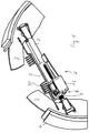
- the FIG. 1 shows a schematic representation of an inner shoe drum brake 1 for motor vehicles.
- the inner shoe drum brake 1 has an adjusting device 2 to compensate for excessive clearance between the brake shoes 3 and Brake drum wall 4.
- the adjusting device 2 has a between the Brake shoes 3 arranged and functionally connected to the brake shoes 3 Push rod 5 on.
- the length of the push rod 5 is to compensate for the excessive Air gap adjustable depending on brake actuation.
- a return spring 30 the brake shoes are activated after actuation, i.e. Spread, back in their Starting position retrieved.
- the inner shoe drum brake 1 is now particularly advantageous. That the adjusting device 2 is designed so that only after a corresponding plurality of brake operations carried out The length of the push rod 5 is adjusted to compensate for excessive air play. As a result, unnecessary additional friction wear between the brake shoes 3 and Brake drum wall 4 avoided, which on the one hand protects the brake shoes 3 ensures, on the other hand, the fuel consumption of the motor vehicle, since unnecessary friction is avoided, minimized accordingly. As a result, the invention offers Inner shoe drum brake 1, especially when used in a not here shown motor vehicle, corresponding economic and ecological advantages.
- FIG. 1,2, 5 and 6 show that the push rod 5 essentially is formed in two parts and a first partial element provided with an external thread 6 and a second partial element 7 provided with a longitudinal bore.
- the first Sub-element 6 is designed here as a spindle and the second sub-element 7 as a hollow cylinder.
- the first partial element 6 designed as a spindle is in the form of a hollow cylinder second sub-element 7 axially insertable.
- FIG. 1 to 4 How the length adjustment of the push rod 5 has been realized here or on which Way the adjuster 2 an excessive clearance between brake shoes 3 and brake drum wall 4 can compensate, will be discussed below.
- FIG. 1 to 4 the underlying principle should become clear.
- For this Reason are in the FIG. 1 to 4 also not all the details, but only those for the principle required details are shown. E.g. is the one when braking pushing apart brake shoes 3 basically in the upper area of FIG. 1 arranged brake pressure cylinder not shown here.
- the partial exploded view of the adjusting device 2 in FIG. 3 shows clearly that the adjusting device 2 has a pawl mechanism 8, one Pawl 9 is provided, which is movable depending on a brake application.
- the Pawl mechanism 8 is when brake operations have taken place or after can be activated accordingly, which will be explained in more detail below. It is crucial, however, that with the help of the pawl mechanism 8 the length adjustment the push rod 5 can be realized.
- FIG. 1, FIG. 3 and FIG. 4 show that the pawl mechanism 8 in addition to the pawl 9th has an angle lever 10 which, with the first partial element 6 designed as a spindle the push rod 5 is engaged.
- the angle lever 10 has a in FIG. 3rd designated opening 11 through which the first sub-element 6 of the push rod 5th extends.
- an adjusting nut 12 is arranged on the unspecified external thread of the first sub-element 6 Push rod 5, an adjusting nut 12 is arranged.
- the adjusting nut 12 is functional with the ratchet mechanism 8 together.
- the adjusting nut 12 does not stand for this directly engaged with the pawl 9 of the pawl mechanism 8, i.e. the adjusting nut 12 and the pawl mechanism 8 do not interact directly, but indirectly.
- Between the Adjusting nut 12 and the pawl mechanism 8 is namely a kind of gear. By arranging this gear between the adjusting nut 12 and Pawl mechanism 8 ensures that only after a certain number brake operations, a corresponding length adjustment of the push rod 5 to compensate for excessive air play.
- FIG. 2 reveals are the adjusting nut 12, an essential part of Pawl mechanism 8 and the corresponding gear in a designated Bearing housing 13 arranged.
- the partial exploded view in FIG. 3 shows that the Pawl 9 of the pawl mechanism 8 with one arranged on a separate shaft 14 first gear 15 cooperates.
- On the separate shaft 14 is an additional Clutch gear 16 arranged, the functional with the adjusting nut 12 directly cooperates (see illustration in FIG. 4).
- the clutch gear 16 Through the first gear 15, the clutch gear 16, the adjusting nut 12 and on the first gear 15, on the clutch gear 16 and on the circumference of the Adjusting nut 12 provided certain number of teeth 15a, 16a and 12a is one Kind of gear formed, so that only after a certain majority Brake operations, preferably a corresponding after ten brake operations
- the length of the push rod 5 is adjusted to compensate for excessive air play.
- the first partial element 6 is tilted Push rod 5, so that the angle lever 10 a corresponding movement on the pawl 9th transmits and this is operated accordingly to act on the first gear 15.
- the sequence of movements of the adjusting device 2 is essentially as follows:
- the brake pressure cylinder presses the Brake shoes 3 apart so that they rest against the brake drum wall 4 can. Since the first part element 6 is inserted axially into the second part element 7, can - as shown in FIG. 2 can be seen - the first sub-element 6 turns slightly outwards move so that the first sub-element 6 can tilt slightly and so the angle lever 10 moves.
- the first sub-element 6 moves into it Starting position back until the adjusting nut 12 again on the angle lever 10 or Bearing housing 13 abuts, the angle lever 10 in turn being moved accordingly. Due to the movement of the angle lever 10, it leads in the pawl mechanism 8 provided pawl 9 a corresponding movement and rotates the first gear 15.
- the clutch gear 16 leads a corresponding Turn off.
- the clutch gear 16 has only two opposite teeth 16a, so that the pawl 9 due to a plurality of Brake operations corresponding to individual additive turns of the first Gear 15 caused until a tooth 16a of the clutch gear 16 with the Adjusting nut 12 is engaged to rotate the adjusting nut 12 accordingly. Only by the rotation of the adjusting nut 12 will then correspond to the length of the push rod 5 changed because by the rotation of the adjusting nut 12 a change in the position of the Adjusting nut 12 on the first partial element 6 of the push rod, which is designed as a spindle 5 is done. The result is the entire effective length of the push rod 5 set accordingly so that excessive ventilation can be compensated.
- the inner shoe drum brake 1 shown here can be very advantageous Brake drums are used, which are made of aluminum, which is the beginning brings the advantages described.
Landscapes
- Engineering & Computer Science (AREA)
- General Engineering & Computer Science (AREA)
- Mechanical Engineering (AREA)
- Braking Arrangements (AREA)
Abstract
Description
- FIG. 1
- die erfindungsgemäße Innenbacken-Trommelbremse,
- FIG. 2
- den linken Teil der erfindungsgemäßen Innenbacken-Trommelbremse aus FIG. 1 in einer vergrößerten Darstellung,
- FIG. 3
- das Lagergehäuse der Nachstellvorrichtung der erfindungsgemäßen Innenbacken-Trommelbremse in einer explosionsartigen teilweisen Darstellung,
- FIG. 4
- eine Darstellung ähnlich der nach FIG. 3, wobei in dieser Explosionsdarstellung mehrere Elemente dargestellt sind,
- FIG. 5
- eine Unteransicht eines Ausschnitts der Druckstange aus FIG. 1,
- Fig. 6
- eine Schnittansicht eines Ausschnitts der Druckstange aus FIG. 1.
Claims (12)
- Innenbacken-Trommelbremse (1), insbesondere für Kraftfahrzeuge, mit einer Nachstellvorrichtung (2) zum Ausgleich eines übermäßigen Lüftspiels zwischen Bremsbacken (3) und Bremstrommelwandung (4), wobei die Nachstellvorrichtung (2) eine zwischen den Bremsbacken (3) angeordnete und funktionell mit diesen verbundene Druckstange (5) aufweist und die Länge der Druckstange (5) zum Ausgleich des übermäßigen Lüftspiels in Abhängigkeit von Bremsbetätigungen verstellbar ist, dadurch gekennzeichnet, daß die Nachstellvorrichtung (2) so ausgebildet ist, daß erst nach einer bestimmten Mehrzahl erfolgter Bremsbetätigungen eine entsprechende Längeneinstellung der Druckstange (5) zum Ausgleich eines übermäßigen Lüftspiels erfolgt.
- Innenbacken-Trommelbremse nach dem vorhergehenden Anspruch, dadurch gekennzeichnet, daß die Druckstange (5) im wesentlichen zweigeteilt ausgebildet ist und ein mit einem Außengewinde versehenes erstes Teilelement (6) und ein mit einer Längsbohrung versehenes zweites Teilelement (7) aufweist.
- Innenbacken-Trommelbremse nach einem der vorhergehenden Ansprüche, dadurch gekennzeichnet, daß das erste Teilelement (6) in das zweite Teilelement (7) axial einschiebbar ist und das erste Teilelement (6) als Spindel und das zweite Teilelement (7) als Hohlzylinder ausgebildet ist.
- Innenbacken-Trommelbremse nach einem der vorhergehenden Ansprüche, dadurch gekennzeichnet, daß die Nachstellvorrichtung (2) einen Klinkenmechanismus (8) mit einer in Abhängigkeit einer Bremsbetätigung bewegbaren Klinke (9) aufweist und der Klinkenmechanismus (8) bei erfolgenden bzw. nach erfolgten Bremsbetätigungen entsprechend aktivierbar ist und mit dessen Hilfe die Längeneinstellung der Druckstange (5) realisierbar ist.
- Innenbacken-Trommelbremse nach einem der vorhergehenden Ansprüche, dadurch gekennzeichnet, daß der Klinkenmechanismus (8) zusätzlich einen Winkelhebel (10) aufweist, der mit dem ersten Teilelement (6) in Eingriff steht.
- Innenbacken-Trommelbremse nach einem der vorhergehenden Ansprüche, dadurch gekennzeichnet, daß auf dem das Außengewinde aufweisenden ersten Teilelement (6) der Druckstange (5) eine Einstellmutter (12) angeordnet ist und die Einstellmutter (12) funktionell mit dem Klinkenmechanismus (8) zusammenwirkt.
- Innenbacken-Trommelbremse nach einem der vorhergehenden Ansprüche, dadurch gekennzeichnet, daß funktionell zwischen der Einstellmutter (12) und dem Klinkenmechanismus (8) ein Getriebe angeordnet ist, so daß erst nach einer bestimmten Mehrzahl erfolgter Bremsbetätigungen eine entsprechende Längeneinstellung der Druckstange (5) zum Ausgleich eines übermäßigen Lüftspiels erfolgt.
- Innenbacken-Trommelbremse nach einem der vorhergehenden Ansprüche, dadurch gekennzeichnet, daß die Einstellmutter (12), ein wesentlicher Teil des Klinkenmechanismus (8) und das entsprechende Getriebe in einem hierfür vorgesehen Lagergehäuse (13) angeordnet ist.
- Innenbacken-Trommelbremse nach einem der vorhergehenden Ansprüche, dadurch gekennzeichnet, daß die Klinke (9) des Klinkenmechanismus (8) mit einem auf einer separaten Welle (14) angeordneten ersten Zahnrad (15) zusammenwirkt.
- Innenbacken-Trommelbremse nach einem der vorhergehenden Ansprüche, dadurch gekennzeichnet, daß auf der separaten Welle (14) zusätzlich ein Kupplungszahnrad (16) angeordnet ist, das mit der Einstellmutter (12) direkt funktionell zusammenwirkt.
- Innenbacken-Trommelbremse nach einem der vorhergehenden Ansprüche, dadurch gekennzeichnet, daß durch das erste Zahnrad (15), das Kupplungszahnrad (16), die Einstellmutter (12) und die auf dem ersten Zahnrad (15), auf dem Kupplungszahnrad (16) und auf der am Umfang der Einstellmutter (12) vorgesehen bestimmten Anzahl von Zähnen (15a, 16a, 12a) eine Art Getriebe gebildet ist, so daß erst nach einer bestimmten Mehrzahl erfolgter Bremsbetätigungen, vorzugsweise nach zehn Bremsbetätigungen, eine entsprechende Längeneinstellung der Druckstange (5) zum Ausgleich eines übermäßigen Lüftspiels erfolgt.
- Innenbacken-Trommelbremse nach einem der vorhergehenden Ansprüche, dadurch gekennzeichnet, daß bei einer Bremsbetätigung ein Kippen des ersten Teilelements (6) erfolgt, so daß der Winkelhebel (10) eine entsprechende Bewegung auf die Klinke (9) überträgt, so daß diese entsprechend betätigt wird.
Applications Claiming Priority (2)
| Application Number | Priority Date | Filing Date | Title |
|---|---|---|---|
| DE19801789 | 1998-01-19 | ||
| DE19801789A DE19801789A1 (de) | 1998-01-19 | 1998-01-19 | Innenbacken-Trommelbremse |
Publications (3)
| Publication Number | Publication Date |
|---|---|
| EP0930446A2 true EP0930446A2 (de) | 1999-07-21 |
| EP0930446A3 EP0930446A3 (de) | 1999-07-28 |
| EP0930446B1 EP0930446B1 (de) | 2004-05-19 |
Family
ID=7855019
Family Applications (1)
| Application Number | Title | Priority Date | Filing Date |
|---|---|---|---|
| EP98123077A Expired - Lifetime EP0930446B1 (de) | 1998-01-19 | 1998-12-10 | Automatische Nachstellvorrichtung für eine Innenbacken-Trommelbremse |
Country Status (2)
| Country | Link |
|---|---|
| EP (1) | EP0930446B1 (de) |
| DE (2) | DE19801789A1 (de) |
Cited By (1)
| Publication number | Priority date | Publication date | Assignee | Title |
|---|---|---|---|---|
| FR2941025A1 (fr) * | 2009-01-14 | 2010-07-16 | Bosch Gmbh Robert | Frein a tambour comprenant un moyen ameliore de rattrapage automatique incremental du jeu entre tambour et garniture. |
Family Cites Families (4)
| Publication number | Priority date | Publication date | Assignee | Title |
|---|---|---|---|---|
| FR766811A (fr) * | 1934-01-10 | 1934-07-04 | Dispositif de contrôle thermostatique pour appareils d'auto-réglage de freins | |
| GB1364443A (en) * | 1970-10-06 | 1974-08-21 | Girling Ltd | Automatic adjusters for internal shoe vehicle wheel drum brakes |
| US4503949A (en) * | 1982-11-01 | 1985-03-12 | Societe Anonyme D.B.A. | Drum brake and the spacer for such a brake |
| FR2604230B1 (fr) * | 1986-09-24 | 1988-12-02 | Bendix France | Entretoise de reglage automatique pour frein a tambour et flan pour la realisation du corps d'une telle entretoise. |
-
1998
- 1998-01-19 DE DE19801789A patent/DE19801789A1/de not_active Withdrawn
- 1998-12-10 EP EP98123077A patent/EP0930446B1/de not_active Expired - Lifetime
- 1998-12-10 DE DE59811421T patent/DE59811421D1/de not_active Expired - Lifetime
Cited By (1)
| Publication number | Priority date | Publication date | Assignee | Title |
|---|---|---|---|---|
| FR2941025A1 (fr) * | 2009-01-14 | 2010-07-16 | Bosch Gmbh Robert | Frein a tambour comprenant un moyen ameliore de rattrapage automatique incremental du jeu entre tambour et garniture. |
Also Published As
| Publication number | Publication date |
|---|---|
| DE59811421D1 (de) | 2004-06-24 |
| EP0930446B1 (de) | 2004-05-19 |
| EP0930446A3 (de) | 1999-07-28 |
| DE19801789A1 (de) | 1999-07-22 |
Similar Documents
| Publication | Publication Date | Title |
|---|---|---|
| DE102012108672B3 (de) | Nachstelleinrichtung einer Scheibenbremse, eine entsprechende Scheibenbremse und Verfahren zum Betreiben einer Verschleißnachstellvorrichtung einer Scheibenbremse | |
| EP2195218B1 (de) | Kugelgewindetrieb für eine kraftfahrzeugbremse und kraftfahrzeugbremse | |
| DE19807328C2 (de) | Elektromechanisch betätigbare Scheibenbremse | |
| EP2682635B1 (de) | Bremsbetätigungsmechanismus für eine Scheibenbremse | |
| DE102014113826B4 (de) | Nachstelleinrichtung einer Scheibenbremse, und eine entsprechende Scheibenbremse | |
| DE4308704A1 (de) | Druckluftbetätigte Scheibenbremse | |
| DE19507308A1 (de) | Scheibenbremse | |
| DE102012108676B3 (de) | Scheibenbremse mit einer Verschleißnachstellvorrichtung | |
| EP3102845A1 (de) | Fahrzeugscheibenbremse | |
| DE2239602C2 (de) | Selbsttätige Nachstellvorrichtung für eine Bremse | |
| DE4215200C2 (de) | Betätigungsvorrichtung für eine Gleitsattel-Scheibenbremse | |
| DE69533376T2 (de) | Normal angelegte Bremse | |
| DE2362283A1 (de) | Spielnachstell-vorrichtung | |
| DE102017114664B4 (de) | Federspeicherbremszylinder mit einer Notlöseeinrichtung | |
| WO2004061324A2 (de) | Scheibenbremse mit elektromotorischer nachstellung | |
| WO2000037819A1 (de) | Getriebeähnlich ausgebildete vorrichtung zur betätigung der bremsbacken | |
| DE2261843B2 (de) | Selbsttaetige, doppeltwirkende bremsgestaengenachstelleinrichtung im bremsgestaenge, insbesondere von schienenfahrzeugen | |
| EP0930446B1 (de) | Automatische Nachstellvorrichtung für eine Innenbacken-Trommelbremse | |
| DE3332548A1 (de) | Feststellbare festsattel-scheibenbremse | |
| DE69805175T2 (de) | Verbesserungen an scheibenbremseinheiten | |
| EP1013959B1 (de) | Hydraulisch betriebener Radbremszylinder zur Betätigung der Bremsbacken einer Trommelbremse | |
| DE102019005094B3 (de) | Nachstelleinheit für eine Bremse und Herstellungsverfahren hierfür | |
| DE102023211097A1 (de) | Elektromechanisches Bremssystem | |
| DE2429706C2 (de) | Selbsttätige Nachstellvorrichtung | |
| DE102014208209A1 (de) | Schiebeelement für eine Nachstelleinrichtung einer Reibkupplung |
Legal Events
| Date | Code | Title | Description |
|---|---|---|---|
| PUAI | Public reference made under article 153(3) epc to a published international application that has entered the european phase |
Free format text: ORIGINAL CODE: 0009012 |
|
| PUAL | Search report despatched |
Free format text: ORIGINAL CODE: 0009013 |
|
| AK | Designated contracting states |
Kind code of ref document: A2 Designated state(s): DE ES FR GB IT |
|
| AX | Request for extension of the european patent |
Free format text: AL;LT;LV;MK;RO;SI |
|
| AK | Designated contracting states |
Kind code of ref document: A3 Designated state(s): AT BE CH CY DE DK ES FI FR GB GR IE IT LI LU MC NL PT SE |
|
| AX | Request for extension of the european patent |
Free format text: AL;LT;LV;MK;RO;SI |
|
| 17P | Request for examination filed |
Effective date: 20000128 |
|
| AKX | Designation fees paid |
Free format text: DE ES FR GB IT |
|
| 17Q | First examination report despatched |
Effective date: 20021107 |
|
| GRAP | Despatch of communication of intention to grant a patent |
Free format text: ORIGINAL CODE: EPIDOSNIGR1 |
|
| GRAS | Grant fee paid |
Free format text: ORIGINAL CODE: EPIDOSNIGR3 |
|
| GRAA | (expected) grant |
Free format text: ORIGINAL CODE: 0009210 |
|
| AK | Designated contracting states |
Kind code of ref document: B1 Designated state(s): DE ES FR GB IT |
|
| PG25 | Lapsed in a contracting state [announced via postgrant information from national office to epo] |
Ref country code: IT Free format text: LAPSE BECAUSE OF FAILURE TO SUBMIT A TRANSLATION OF THE DESCRIPTION OR TO PAY THE FEE WITHIN THE PRESCRIBED TIME-LIMIT;WARNING: LAPSES OF ITALIAN PATENTS WITH EFFECTIVE DATE BEFORE 2007 MAY HAVE OCCURRED AT ANY TIME BEFORE 2007. THE CORRECT EFFECTIVE DATE MAY BE DIFFERENT FROM THE ONE RECORDED. Effective date: 20040519 Ref country code: GB Free format text: LAPSE BECAUSE OF FAILURE TO SUBMIT A TRANSLATION OF THE DESCRIPTION OR TO PAY THE FEE WITHIN THE PRESCRIBED TIME-LIMIT Effective date: 20040519 Ref country code: FR Free format text: LAPSE BECAUSE OF FAILURE TO SUBMIT A TRANSLATION OF THE DESCRIPTION OR TO PAY THE FEE WITHIN THE PRESCRIBED TIME-LIMIT Effective date: 20040519 |
|
| REG | Reference to a national code |
Ref country code: GB Ref legal event code: FG4D Free format text: NOT ENGLISH |
|
| REF | Corresponds to: |
Ref document number: 59811421 Country of ref document: DE Date of ref document: 20040624 Kind code of ref document: P |
|
| PG25 | Lapsed in a contracting state [announced via postgrant information from national office to epo] |
Ref country code: ES Free format text: LAPSE BECAUSE OF FAILURE TO SUBMIT A TRANSLATION OF THE DESCRIPTION OR TO PAY THE FEE WITHIN THE PRESCRIBED TIME-LIMIT Effective date: 20040830 |
|
| GBV | Gb: ep patent (uk) treated as always having been void in accordance with gb section 77(7)/1977 [no translation filed] |
Effective date: 20040519 |
|
| PLBE | No opposition filed within time limit |
Free format text: ORIGINAL CODE: 0009261 |
|
| STAA | Information on the status of an ep patent application or granted ep patent |
Free format text: STATUS: NO OPPOSITION FILED WITHIN TIME LIMIT |
|
| 26N | No opposition filed |
Effective date: 20050222 |
|
| EN | Fr: translation not filed | ||
| PGFP | Annual fee paid to national office [announced via postgrant information from national office to epo] |
Ref country code: DE Payment date: 20110111 Year of fee payment: 13 |
|
| REG | Reference to a national code |
Ref country code: DE Ref legal event code: R119 Ref document number: 59811421 Country of ref document: DE Effective date: 20120703 |
|
| PG25 | Lapsed in a contracting state [announced via postgrant information from national office to epo] |
Ref country code: DE Free format text: LAPSE BECAUSE OF NON-PAYMENT OF DUE FEES Effective date: 20120703 |