EP0930157A2 - Method for fixing plastic film on the back side of a decorative material before back-foaming - Google Patents
Method for fixing plastic film on the back side of a decorative material before back-foaming Download PDFInfo
- Publication number
- EP0930157A2 EP0930157A2 EP98123731A EP98123731A EP0930157A2 EP 0930157 A2 EP0930157 A2 EP 0930157A2 EP 98123731 A EP98123731 A EP 98123731A EP 98123731 A EP98123731 A EP 98123731A EP 0930157 A2 EP0930157 A2 EP 0930157A2
- Authority
- EP
- European Patent Office
- Prior art keywords
- decorative material
- plastic film
- mold
- tool
- negative
- Prior art date
- Legal status (The legal status is an assumption and is not a legal conclusion. Google has not performed a legal analysis and makes no representation as to the accuracy of the status listed.)
- Granted
Links
Images

Classifications
-
- B—PERFORMING OPERATIONS; TRANSPORTING
- B32—LAYERED PRODUCTS
- B32B—LAYERED PRODUCTS, i.e. PRODUCTS BUILT-UP OF STRATA OF FLAT OR NON-FLAT, e.g. CELLULAR OR HONEYCOMB, FORM
- B32B37/00—Methods or apparatus for laminating, e.g. by curing or by ultrasonic bonding
- B32B37/10—Methods or apparatus for laminating, e.g. by curing or by ultrasonic bonding characterised by the pressing technique, e.g. using action of vacuum or fluid pressure
- B32B37/1018—Methods or apparatus for laminating, e.g. by curing or by ultrasonic bonding characterised by the pressing technique, e.g. using action of vacuum or fluid pressure using only vacuum
-
- B—PERFORMING OPERATIONS; TRANSPORTING
- B32—LAYERED PRODUCTS
- B32B—LAYERED PRODUCTS, i.e. PRODUCTS BUILT-UP OF STRATA OF FLAT OR NON-FLAT, e.g. CELLULAR OR HONEYCOMB, FORM
- B32B38/00—Ancillary operations in connection with laminating processes
- B32B38/0036—Heat treatment
Definitions
- Reference number 1 denotes a flat decorative material, which is preferred Leather, but can also be a textile fabric or Alcantara and later foamed and possibly with a carrier part, not shown to be connected to, for example, a vehicle interior trim part to build.
- a plastic film 2 in particular consisting of TPU or TPE, to be applied in the case of the back-foaming which has just been mentioned with a plastic foam material to penetrate it To prevent plastic foam in the decorative material 1.
- the decorative material 1 lies with its front side on a tool mold 3 whose surface is essentially a negative image of the desired one Shape of the finished part to be ultimately achieved, i.e. for example the Vehicle interior trim is.
- the decorative material 1 is thus on this Tool form 3 already preformed on top, whereby the decorative material 1 on this mold 3 or on the surface it is held by negative pressure, i.e. to the surface of the mold 3 a vacuum is applied, for which purpose corresponding channels 4, which the surface of the mold 3 open, provided in this mold 3 are.
- These channels 4 are at their opposite ends connected to a vacuum pump (not shown).
- the performance of this vacuum pump is chosen such that the decorative material 1 is secure the surface of the mold 3 can be held, although that Decorative material 1 itself is at least slightly permeable to air.
- the decorative material 1 can be placed in a particularly advantageous manner on the tool mold 3 and how it can be preformed therein:
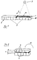
- the decorative material 1 before being placed on the mold 3, is placed on a corresponding negative mold 8 with the decorative material visible on the front and is also held there by negative pressure (cf. channels 4 for applying negative pressure).
- the back of the decorative material 1 is thus placed on the negative mold 8, so that its front side is visible and the decorative material 1 can thus be positioned as actually desired.
- any seams that may be present one is designated by the reference number 10 can be placed in the decorative material 1 as desired, for which purpose the decorative material 1 can be shifted slightly on the surface of the negative mold 8, for example.
- the vacuum applied analogously to tool mold 3 must be of a corresponding size so that decorative material 1 is held on the surface of negative mold 8, but can nevertheless be displaced slightly parallel to its surface.
- the now on the exposed back of the decorative material 1 plastic film to be applied 2 prepared.
- This is essentially in a tenter 5 held above the mold 3 and spaced from it.
- this plastic film 2 held in the tenter 5 heated by means of one above the plastic film 2 and thus on the side facing away from the mold 3 of the same provided heating device 6.
- This heating device 6 can be, for example flat infrared heaters or with a hot air blower a plurality of blower outlet openings directed towards the plastic film 2 act.
- thermoplastic film 2 becomes almost heated up to its melting point so that it is now easy be placed on the back of the decorative material 1 and laminated on can.
- the negative pressure still present on the surface of the mold 3 ensures that the plastic film 2 flat on the back of the decorative material 1 comes to rest after the latter at least slightly is permeable to air.
- the plastic film 2 laminated glue-free onto the decorative material 1 this one Method step is not explicitly shown, since it can be done as usual.
- the heating device 6 is removed and cooling the composite of decorative material 1 and plastic film 2 initiated. Then this composite of decorative material 1 and plastic film 2 are removed from the mold 3, wherein one advantageously hereby quasi an already prefabricated semi-finished product Has disposal; in addition, however, it is also possible to use the decorative material 1 the provided on the back of the plastic film 2 still in the Foam tool mold 3, which is of course a suitable one Counter tool is needed.
- plastic film 2 only can be melted in certain areas into the decorative material 1: 4 between the heating device 6 and the plastic film 2 positioned a suitable screen 7 in such a way that in the area of or below this screen 7 no direct heat done on the plastic film 2.
- this can also a similar aperture 7 is also positioned in the method step according to FIG. 3 if a certain surface section of the plastic film 2 should not be melted at all. In those areas in which then, in particular in the post-heating phase according to FIG. 4, no heat takes place on the plastic film 2, the described intimate Connection between this and the decorative material 1 is not established.
Abstract
Description
Die Erfindung betrifft ein Verfahren zum Aufkaschieren einer Kunststoff-Folie auf die Rückseite eines danach zu hinterschäumenden zumindest geringfügig luftdurchlässigen, flächigen Dekormaterials, insbesondere aus Leder oder Textil oder Alcantara, wobei die zunächst in einem Spannrahmen gehaltene Kunststoff-Folie erwärmt und so auf die Rückseite des mittels Unterdruck an einer Werkzeugform gehaltenen Dekormaterials aufgebracht wird. Zum bekannten Stand der Technik wird auf die US 4,758,294 verwiesen.The invention relates to a method for laminating a plastic film on the back of one to be back-foamed afterwards at least slightly air-permeable, flat decorative material, in particular made of leather or textile or Alcantara, the one initially held in a stenter Plastic film is heated and so on the back of the by means of negative pressure is applied to a mold held decorative material. For the known prior art, reference is made to US 4,758,294.
Soll beispielsweise zur Herstellung eines Fahrzeug-Innenausstattungsteiles ein zumindest geringfügig luftdurchlässiges Dekormaterial hinterschäumt werden, d.h. soll auf die Rückseite dieses beispielsweise aus Leder oder einem Textilgewebe oder Alcantara oder dgl. bestehenden Dekormaterials eine Kunststoff-Schaumschicht aufgebracht werden, so sind Maßnahmen zu treffen, die ein Eindringen des Kunststoff-Schaummateriales in das Dekormaterial oder sogar ein Durchdringen desselben verhindern. For example, for the production of a vehicle interior part foams an at least slightly air-permeable decorative material become, i.e. should be on the back of this for example made of leather or a textile fabric or Alcantara or the like. existing decorative material a plastic foam layer are applied, so measures are too meet the penetration of the plastic foam material into the decorative material or even prevent it from penetrating.
Eine mögliche derartige Maßnahme ist in der oben genannten US 4,758,294 gezeigt. Demnach wird auf der Rückseite des Dekormaterials vor dem Hinterschäumen eine Kunststoff-Folie aufkaschiert, die mit einem Heißschmelzkleber vorbeschichtet ist. Diese Kunststoff-Folie wird hierzu - gehalten in einem Spannrahmen - erwärmt, wodurch der Kleber in den schmelzflüssigen Zustand übergeht und gleichzeitig die Kunststoff-Folie so weit erweicht wird, daß sie in optimaler Weise auf die Rückseite des Dekormaterials aufkaschiert, d.h. aufgeklebt werden kann. Dabei wird die Kunststoff-Folie durch Unterdruck an die Rückseite des Dekormaterials herangezogen, wobei dieser Unterdruck von Seiten einer Werkzeugform ausgeht, auf welchem das Dekormaterial aufliegt.A possible measure of this type is in the above-mentioned US 4,758,294 shown. Accordingly, on the back of the decorative material before foaming laminated a plastic film with a hot melt adhesive is precoated. This plastic film is - held in one Tensioning frame - heated, causing the glue in the molten Condition passes and at the same time the plastic film is softened so far, that it is optimally laminated onto the back of the decorative material, i.e. can be glued on. The plastic film is through Vacuum applied to the back of the decorative material, this Negative pressure comes from the side of a mold on which the Decorative material rests.
Abgesehen davon, daß der Schmelzkleber, mit welchem die Kunststoff-Folie beschichtet ist, einen wünschenswerterweise zu vermeidenden Aufwand darstellt, sind mit dem bekannten Verfahren keine unter allen Umständen befriedigenden Ergebnisse erzielbar. Insbesondere in Bereichen, in denen die Kunststoff-Folie beim Aufkaschieren auf das Dekormaterial, welches wie bekannt und üblich eine der Werkzeugform entsprechende und von einer Ebene mehr oder weniger abweichende Formgebung aufweist, relativ stark umgeformt oder gedehnt werden muß, wirkt sich der schnell haftende Schmelzkleber nachteilig aus.Apart from that the hot melt adhesive with which the plastic film is coated, an effort to be avoided desirably represents, with the known method are none under all circumstances satisfactory results. Especially in areas where the plastic film when laminated onto the decorative material, which like known and customary one of the tool shape and from one Level has more or less different shapes, relatively strong must be reshaped or stretched, the fast-adhering effect Hot melt adhesive disadvantageous.
Im Hinblick hierauf ein verbessertes Verfahren nach dem Oberbegriff des
Anspruchs 1 aufzuzeigen, ist Aufgabe der vorliegenden Erfindung.
Die Lösung dieser Aufgabe ist dadurch gekennzeichnet, daß die Kunststoff-Folie
kleberlos auf das Dekormaterial aufkaschiert und unter weiterer Wärmeeinwirkung
zumindest geringfügig in dieses eingeschmolzen wird, wobei
der hierzu erforderliche Anpreßdruck durch den weiterhin über die Werkzeugform
einwirkenden Unterdruck erzeugt wird. Vorteilhafte Weiterbildungen
sind Inhalt der Unteransprüche.In view of this, it is an object of the present invention to show an improved method according to the preamble of
The solution to this problem is characterized in that the plastic film is laminated adhesive-free onto the decorative material and at least slightly melted into it under the influence of further heat, the contact pressure required for this being generated by the underpressure which continues to act via the mold. Advantageous further developments are included in the subclaims.
Näher erläutert wird die Erfindung anhand eines bevorzugten Ausführungsbeispieles anhand von vier Prinzipskizzen, die einzelne Verfahrensschritte wiedergeben, wobei der den wesentlichen Verfahrensschritten nach den Fig. 2 bis 4 vorgeschaltete Verfahrensschritt nach Fig. 1 eine vorteilhafte Weiterbildung der Erfindung beinhaltet.The invention is explained in more detail with reference to a preferred exemplary embodiment based on four sketches, the individual process steps reproduce, the essential process steps according to FIGS. 2 to 4 upstream method step according to FIG. 1 an advantageous development of the invention includes.
Mit der Bezugsziffer 1 ist ein flächiges Dekormaterial bezeichnet, das bevorzugt
Leder, daneben jedoch auch ein Textilgewebe oder Alcantara sein kann
und das später hinterschäumt und ggf. mit einem nicht dargestellten Trägerteil
verbunden werden soll, um beispielsweise ein Fahrzeug-Innenausstattungsteil
zu bilden. Auf die Rückseite dieses flächigen Dekormaterials 1
soll zunächst eine Kunststoff-Folie 2, insbesondere aus TPU oder TPE bestehend,
aufgebracht werden, um beim späteren soeben genannten Hinterschäumen
mit einem Kunststoffschaummaterial ein Eindringen dieses
Kunststoffschaumes in das Dekormaterial 1 zu verhindern.
Im Rahmen der wesentlichen Verfahrensschritte der vorliegenden Erfindung
liegt das Dekormaterial 1 mit seiner Vorderseite auf einer Werkzeugform 3
auf, deren Oberfläche im wesentlichen ein Negativbild der gewünschten
Form des letztendlich zu erzielenden Fertigteiles, d.h. beispielsweise des
Fahrzeug-Innenausstattungsteiles ist. Das Dekormaterial 1 ist somit auf dieser
Werkzeugform 3 aufliegend bereits im wesentlichen vorgeformt, wobei
das Dekormaterial 1 auf dieser Werkzeugform 3 bzw. auf der Oberfläche
desselben durch Unterdruck gehalten wird, d.h. an die Oberfläche der Werkzeugform
3 wird ein Vakuum angelegt, wozu entsprechende Kanäle 4, die an
der Oberfläche der Werkzeugform 3 münden, in dieser Werkzeugform 3 vorgesehen
sind. Mit ihren entgegengesetzten Enden sind diese Kanäle 4 mit
einer Unterdruckpumpe verbunden (nicht gezeigt). Die Leistung dieser Unterdruckpumpe
ist dabei derart gewählt, daß das Dekormaterial 1 sicher auf
der Oberfläche der Werkzeugform 3 gehalten werden kann, wenngleich das
Dekormaterial 1 selbst zumindest geringfügig luftdurchlässig ist.Within the essential process steps of the present invention
the
Zunächst wird nun erläutert, wie das Dekormaterial 1 in besonders vorteilhafter
Weise auf die Werkzeugform 3 aufgelegt sowie in dieser vorgeformt
werden kann:
Wie Fig. 1 zeigt, wird das Dekormaterial 1 vor dem Auflegen auf die Werkzeugform
3 auf einer mit dieser korrespondierenden Negativform 8 bei sichtbarer
Dekormaterial-Vorderseite aufgelegt ausgerichtet und dabei an dieser
ebenfalls durch Unterdruck (vgl. Kanäle 4 zum Anlegen von Unterdruck) gehalten.
Das Dekormaterial 1 wird somit mit seiner Rückseite auf die Negativform
8 aufgelegt, so daß dessen Vorderseite sichtbar ist und hiermit das
Dekormaterial 1 wie tatsächlich gewünscht positioniert werden kann. Beispielsweise
können auf diese Weise auch evtl. vorhandene Nähte (eine solche
ist mit der Bezugsziffer 10 bezeichnet) im Dekormaterial 1 wie gewünscht
plaziert werden, wozu das Dekormaterial 1 auf der Oberfläche der
Negativform 8 beispielsweise geringfügig verschoben werden kann. Selbstverständlich
muß hierzu der analog zur Werkzeugform 3 angelegte Unterdruck
von einer dementsprechenden Größe sein, daß das Dekormaterial 1
zwar auf der Oberfläche der Negativform 8 gehalten wird, jedoch trotzdem
geringfügig parallel zu dessen Oberfläche verschiebbar ist.First of all, it will now be explained how the
As shown in FIG. 1, the
Um dabei eine Vorlage zur Verfügung zu haben, wie das Dekormaterial 1 auf
der Negativform 8 zu positionieren ist, kann zum Erleichtern des Ausrichtens
dieses Dekormateriales 1 dessen Sollposition mittels einer Projektionseinrichtung
9 auf die Vorderseite des Dekormaterials 1 optisch aufprojiziert werden. In order to have a template available, such as
Nach erfolgreicher Ausrichtung des Dekormateriales 1 auf der Negativform 8
wird die letztgenannte geeignet über bzw. auf der Werkzeugform 3 positioniert,
was bevorzugt durch eine Schwenkbewegung gemäß Pfeilrichtung 11
erfolgt, so daß das Dekormaterial 1 nunmehr von der Negativform 8 an die
Werkzeugform 3 übergeben werden kann. In diesem in Fig. 2 dargestellten
Stadium wird das Dekormaterial 1 dabei auch zumindest teilweise vorgeformt,
wobei einerseits die Anpreßkraft der Negativform 8 auf die Werkzeugform
3 wirksam ist und andererseits der an der Oberfläche der Werkzeugform
3 anliegende Unterdruck - wie bereits erläutert - wirkt. Anschließend
wird die Negativform 8 gegen Pfeilrichtung 11 wieder von der Werkzeugform
3 weggeklappt.After the
Im nachfolgenden Verfahrensschritt gemäß Fig. 3 wird nun die auf die nunmehr
offenliegende Rückseite des Dekormateriales 1 aufzubringende Kunststoff-Folie
2 vorbereitet. Diese ist dabei in einem Spannrahmen 5 im wesentlichen
oberhalb der Werkzeugform 3 sowie beabstandet von dieser gehalten.
Zunächst wird nun diese im Spannrahmen 5 gehaltene Kunststoff-Folie 2
erwärmt und zwar mittels einer oberhalb der Kunststoff-Folie 2 und somit auf
der der Werkzeugform 3 abgewandten Seite derselben vorgesehenen Heizvorrichtung
6. Bei dieser Heizvorrichtung 6 kann es sich beispielsweise um
flächig angeordnete Infrarotstrahler oder auch um ein Heißluftgebläse mit
einer Vielzahl von zur Kunststoff-Folie 2 hin gerichteten Gebläse-Austrittsöffnungen
handeln.In the subsequent method step according to FIG. 3, the now on the
exposed back of the
Aufgrund der Erwärmung wird die thermoplastische Kunststoff-Folie 2 nahezu
bis zu ihrem Schmelzpunkt aufgeheizt, so daß sie nun auf einfache Weise
auf die Rückseite des Dekormaterials 1 aufgelegt und aufkaschiert werden
kann. Der an der Oberfläche der Werkzeugform 3 noch anliegende Unterdruck
sorgt dabei dafür, daß die Kunststoff-Folie 2 flächig auf der Rückseite
des Dekormaterials 1 zum Liegen kommt, nachdem letzteres zumindest geringfügig
luftdurchlässig ist. Jedoch ist in diesem Stadium noch keine innige
Verbindung zwischen dem Dekormaterial 1 sowie der Kunststoff-Folie 2 hergestellt,
da kein Klebstoff oder dgl. verwendet wird. Vielmehr wird die Kunststoff-Folie
2 kleberlos auf das Dekormaterial 1 aufkaschiert, wobei dieser
Verfahrensschritt nicht explizit dargestellt ist, da er wie üblich erfolgen kann.Due to the heating, the
Dargestellt jedoch ist der darauffolgende Verfahrensschritt, und zwar in Fig.
4. Bei diesem Verfahrensschritt wird nun die Kunststoff-Folie 2 bzw. das nahezu
geschmolzene Material derselben zumindest geringfügig in das Dekormaterial
1 eingeschmolzen, um eine innige Verbindung zwischen Dekormaterial
1 und Kunststoff-Folie 2 herzustellen. Hierzu wirkt zum einen weiterhin
Unterdruck auf den Verbund von Dekormaterial 1 und Kunststoff-Folie
2 ein, wobei die Kunststoff-Folie aufgrund der zumindest geringfügigen Luftdurchlässigkeit
des Dekormaterials 1 durch diesen Unterdruck in ausreichendem
Maße an die Rückseite des Dekormaterials 1 angepreßt wird.However, the subsequent method step is shown, specifically in FIG.
4. In this process step, the
Insbesondere jedoch erfolgt für diese Herstellung des innigen Verbundes
eine weitere Wärmeeinwirkung auf die Kunststoff-Folie 2 sowie das darunterliegende
Dekormaterial 1, und zwar immer noch in bzw. an der Werkzeugform
3. Die bereits erwähnte Heizvorrichtung 6 wird hierzu geeignet
oberhalb der Werkzeugform 3 bzw. der Kunststoff-Folie 2 positioniert und
aktiviert.In particular, however, this intimate bond is made for this production
a further heat effect on the
In anderen Worten ausgedrückt, erfolgt somit nach dem kleberlosen Aufkaschieren
der nahezu bis zu ihrem Schmelzpunkt erwärmten Kunststoff-Folie
2 auf das Dekormaterial 1 eine Nachheizphase, in welcher die auf das Dekormaterial
1 durch den Unterdruck gepreßte Kunststoff-Folie 2 ohne Verwendung
irgendeines Klebstoffes in das Dekormaterial 1 zumindest geringfügig
eingeschmolzen wird, wodurch die zur nötigen Adhäsion gewünschte
Haftbrücke ausgebildet wird.In other words, it takes place after the adhesive-free lamination
the plastic film warmed up almost to its
Nach Beendigung dieser Nachheizphase wird die Heizvorrichtung 6 entfernt
und die Kühlung des Verbundes von Dekormaterial 1 und Kunststoff-Folie 2
eingeleitet. Anschließend daran kann dieser Verbund von Dekormaterial 1
und Kunststoff-Folie 2 aus der Werkzeugform 3 entnommen werden, wobei
man hiermit vorteilhafterweise quasi ein bereits vorgefertigtes Halbzeug zur
Verfügung hat; daneben ist es jedoch auch möglich, das Dekormaterial 1 mit
der auf dessen Rückseite vorgesehenen Kunststoff-Folie 2 noch in der
Werkzeugform 3 zu hinterschäumen, wozu selbstverständlich ein geeignetes
Gegenwerkzeug benötigt wird.After this post-heating phase has ended, the
Das erfindungsgemäße Verfahren erlaubt es auch, die Kunststoff-Folie 2
bezüglich der gesamten rückseitigen Oberfläche des Dekormaterials 1 lediglich
bereichsweise mit diesem innig zu verbinden, falls eine derartige innige
Verbindung nur in ausgewählten Bereichen dieser Oberfläche gewünscht ist.
Dies kann erwünscht sein, wenn in diesen Bereichen die Kunststoff-Folie 2
anschließend an den beschriebenen Verfahrensablauf wieder entfernt werden
soll, beispielsweise um Randzonen des Dekormaterials 1 frei von einer
derartigen Kunststoff-Folie 2 zu halten, bspw. wenn das Dekormaterial 1 in
diesem Randbereich noch weiter verformt oder mit einem Trägermaterial
verklebt werden muß.The method according to the invention also allows the
Eine erste Möglichkeit, wie die Kunststoff-Folie 2 nur bereichsweise in das
Dekormaterial 1 eingeschmolzen werden kann, besteht darin, daß zwischen
der Kunststoff-Folie 2 sowie dem Dekormaterial 1 im entsprechenden Oberflächen-Bereich
eine aus einem geeigneten Material bestehende Folie zwischengelegt
ist, die selbst nicht anschmilzt und somit verhindert, daß das
Material der erweichten Kunststoff-Folie 2 zumindest teilweise in das Dekormaterial
1 eingeschmolzen wird. Diese sog. Zwischen-Folie ist hier jedoch
der Einfachhheit halber nicht dargestellt.A first possibility, such as the
Gezeigt ist vielmehr eine weitere Möglichkeit, wie die Kunststoff-Folie 2 lediglich
bereichsweise in das Dekormaterial 1 eingeschmolzen werden kann:
Hierzu wird beim Verfahrensschritt nach Fig. 4 zwischen der Heizvorrichtung
6 sowie der Kunststoff-Folie 2 eine geeignete Blende 7 derart positioniert,
daß im Bereich der bzw. unterhalb dieser Blende 7 keine direkte Wärmeeinwirkung
auf die Kunststoff-Folie 2 erfolgt. Im übrigen kann diese oder auch
eine ähnliche Blende 7 auch beim Verfahrensschritt nach Fig. 3 positioniert
werden, wenn ein gewisser Oberflächenabschnitt der Kunststoff-Folie 2
überhaupt nicht angeschmolzen werden soll. In denjenigen Bereichen, in
denen dann insbesondere in der Nachheizphase nach Fig. 4 keine Wärmeeinwirkung
auf die Kunststoff-Folie 2 erfolgt, wird auch die beschriebene innige
Verbindung zwischen dieser sowie dem Dekormaterial 1 nicht hergestellt.Rather, another possibility is shown, such as the
Es sei noch darauf hingewiesen, daß dies sowie eine Vielzahl weiterer Details
durchaus abweichend vom beschriebenen Ausführungsbeispiel gestaltet
sein können, ohne den Inhalt der Patentansprüche zu verlassen. Stets
erhält man ein im Hinblick auf ein nachfolgendes Hinterschäumen in optimaler
Weise vorbereitetes Dekormaterial 1, welches vorteilhafterweise als
kleberloses System ausgeführt ist, und an welchem aufgrund der Kunststoff-Folie
2 auch eventuell beim Hinterschäumen ausgetretener Schaum ohne
großen Arbeitsaufwand entfernt werden kann. Aufgrund der Anpressung der
Kunststoff-Folie 2 durch Unterdruck können vorteilhafterweise keine Schubfalten,
wie ansonsten bei mechanischem Anpressen, entstehen. Dabei ist
vorteilhafterweise auch eine Vorfertigung eines derartigen Bezuges, d.h.
Verbundes aus Dekormaterial 1 und Kunststoff-Folie 2 möglich, da durch die
aufkaschierte Kunststoff-Folie 2 das Dekormaterial 1, beispielsweise ein Lederkleid,
seine durch die Werkzeugform 3 vorgegebene Kontur behält.It should be noted that this as well as a host of other details
designed quite differently from the described embodiment
can be without leaving the content of the claims. Always
one obtains an optimal one with regard to subsequent foaming
Wisely prepared
- 11
- DekormaterialDecorative material
- 22nd
- Kunststoff-FoliePlastic film
- 33rd
- WerkzeugformTool shape
- 44th
- Kanäle in 3 zum Halten von 1 durch UnterdruckChannels in 3 for holding 1 by negative pressure
- 55
- SpannrahmenStenter
- 66
- HeizvorrichtungHeater
- 77
- Blendecover
- 88th
- Negativformnegative form
- 99
- ProjektionsvorrichtungProjection device
- 1010th
- Naht in 1Seam in 1st
- 1111
- PfeilrichtungArrow direction
Claims (4)
dadurch gekennzeichnet, daß die Kunststoff-Folie (2) kleberlos auf das Dekormaterial (1) aufkaschiert und unter weiterer Wärmeeinwirkung zumindest geringfügig in dieses eingeschmolzen wird, wobei der hierzu erforderliche Anpreßdruck durch den weiterhin über die Werkzeugform (3) einwirkenden Unterdruck erzeugt wird.Method for laminating a plastic film (2) onto the back of an at least slightly air-permeable, flat decorative material (1) to be back-foamed, in particular made of leather or textile or Alcantara, the plastic film (2) initially held in a clamping frame (5) ) heated and thus applied to the back of the decorative material (1) held on a tool mold (3) by means of negative pressure,
characterized in that the plastic film (2) is laminated without adhesive onto the decorative material (1) and at least slightly melted into it under the influence of further heat, the contact pressure required for this being generated by the underpressure which continues to act via the mold (3).
dadurch gekennzeichnet, daß die Kunststoff-Folie (2) nur bereichsweise in das Dekormaterial (1) eingeschmolzen wird. Method according to claim 1,
characterized in that the plastic film (2) is only partially melted into the decorative material (1).
dadurch gekennzeichnet, daß eine lediglich bereichsweise Wärmeeinwirkung auf die Kunststoff-Folie (2) durch Positionieren einer geeigneten Blende (7) zwischen der Kunststoff-Folie (2) sowie einer Heizvorrichtung (6) realisiert wird.The method of claim 1 or 2,
characterized in that heat is exerted only in certain areas on the plastic film (2) by positioning a suitable screen (7) between the plastic film (2) and a heating device (6).
dadurch gekennzeichnet, daß das Dekormaterial (1) vor dem Auflegen auf die Werkzeugform (3) auf einer mit dieser korrespondierenden Negativform (8) bei sichtbarer Vorderseite ausgerichtet und an dieser durch Unterdruck gehalten wird, wobei zum Erleichtern des Ausrichtens die Sollposition auf die Vorderseite des Dekormaterials (1) aufprojiziert wird und daß anschließend das Dekormaterial (1) von der Negativform (8) an die Werkzeugform (3) übergeben wird.Method according to one of the preceding claims,
characterized in that the decorative material (1) prior to being placed on the tool mold (3) on a corresponding negative mold (8) aligned with the visible front and held thereon by negative pressure, the target position on the front of the Decorative material (1) is projected on and that the decorative material (1) is then transferred from the negative mold (8) to the tool mold (3).
Applications Claiming Priority (2)
| Application Number | Priority Date | Filing Date | Title |
|---|---|---|---|
| DE19801651A DE19801651A1 (en) | 1998-01-15 | 1998-01-15 | Process for laminating a plastic film on the back of a decorative material to be back-foamed afterwards |
| DE19801651 | 1998-01-15 |
Publications (3)
| Publication Number | Publication Date |
|---|---|
| EP0930157A2 true EP0930157A2 (en) | 1999-07-21 |
| EP0930157A3 EP0930157A3 (en) | 2000-07-05 |
| EP0930157B1 EP0930157B1 (en) | 2004-10-27 |
Family
ID=7854917
Family Applications (1)
| Application Number | Title | Priority Date | Filing Date |
|---|---|---|---|
| EP98123731A Expired - Lifetime EP0930157B1 (en) | 1998-01-15 | 1998-12-14 | Method for fixing plastic film on the back side of a decorative material before back-foaming |
Country Status (2)
| Country | Link |
|---|---|
| EP (1) | EP0930157B1 (en) |
| DE (2) | DE19801651A1 (en) |
Cited By (2)
| Publication number | Priority date | Publication date | Assignee | Title |
|---|---|---|---|---|
| WO2008135552A1 (en) * | 2007-05-08 | 2008-11-13 | Basf Se | Method for coating a molded foam part |
| US9278500B2 (en) | 2014-05-06 | 2016-03-08 | Faurecia Interior Systems, Inc. | Vehicle interior panels with sealed stitching |
Families Citing this family (5)
| Publication number | Priority date | Publication date | Assignee | Title |
|---|---|---|---|---|
| DE19959654A1 (en) * | 1999-12-10 | 2001-06-21 | Findlay Ind Deutschland Gmbh | Process for the production of interior components of motor vehicles |
| DE19961314B4 (en) * | 1999-12-18 | 2004-05-19 | Bayerische Motoren Werke Ag | Manufacturing process for a vehicle interior part with a foam-backed leather cover |
| DE102006009006A1 (en) * | 2006-02-23 | 2007-09-06 | Klaus Bachmann | Composite material for protective clothing and upholstery elements for protective clothing made thereof |
| DE102014002564A1 (en) * | 2014-02-26 | 2015-08-27 | Johnson Controls Interiors Gmbh & Co. Kg | Multilayer molding for vehicle interiors and method for producing such moldings |
| WO2015124658A1 (en) | 2014-02-19 | 2015-08-27 | Johnson Controls Interiors Gmbh & Co. Kg | Multi-layered shaped body for internal vehicle fittings and method for producing such shaped bodies |
Citations (4)
| Publication number | Priority date | Publication date | Assignee | Title |
|---|---|---|---|---|
| US4824506A (en) * | 1988-04-21 | 1989-04-25 | General Motors Corporation | Process for protecting thermoformed films |
| DE3924254A1 (en) * | 1988-07-26 | 1990-02-01 | Ikeda Bussan Co | METHOD AND DEVICE FOR PRODUCING A FOAMED OBJECT PROVIDED WITH A COATING LAYER |
| DE4433455A1 (en) * | 1994-09-20 | 1996-03-21 | Bayerische Motoren Werke Ag | Moulding arrangement for foam-backed leather parts for motor vehicle internal linings |
| US5681408A (en) * | 1993-02-05 | 1997-10-28 | Gencorp Inc. | Acoustic lamina wall covering |
Family Cites Families (20)
| Publication number | Priority date | Publication date | Assignee | Title |
|---|---|---|---|---|
| DE908534C (en) * | 1951-12-11 | 1954-04-08 | Hermann Ellinghausen | Process for covering fabrics with thermoplastics |
| DE2126587A1 (en) * | 1970-06-06 | 1971-12-16 | Cromton Plastic Ltd | Process for the production of multi-layer articles from foamed plastic |
| DE2046318A1 (en) * | 1970-09-19 | 1972-04-13 | Basf Ag | Coating leather with polyethylene or polyamide film - using polyethyl film as adhesion promoter |
| DE7637031U1 (en) * | 1976-11-25 | 1977-03-10 | Fa. Willi Illbruck, 5090 Leverkusen | |
| DE3506232C1 (en) * | 1985-02-22 | 1986-08-14 | Grammer Sitzsysteme GmbH, 8450 Amberg | Process for producing seat or backrest upholstery |
| DE3622906A1 (en) * | 1986-07-08 | 1988-01-28 | Helmut W Diedrichs | Foam body and process and device for the production thereof |
| GB2207078B (en) * | 1987-07-10 | 1990-03-07 | Grammer Sitzsysteme Gmbh | Process for the production of a foam backed article |
| DE58901662D1 (en) * | 1988-04-09 | 1992-07-23 | Bayerische Motoren Werke Ag | METHOD FOR SHAPING NATURAL LEATHER. |
| DE4012006A1 (en) * | 1990-04-13 | 1991-10-17 | Bayer Ag | RIM of polyurethane polyurea mould-lining film - with film then being vacuum formed into mould which is used to produce film-lined mouldings of complex shape |
| EP0569846A2 (en) * | 1992-05-13 | 1993-11-18 | R + S STANZTECHNIK GmbH | Apparatus for producing trim panels and method for securing such trim panels to a support |
| DE4307816C2 (en) * | 1993-03-12 | 1995-11-23 | Buerkle Gmbh & Co Robert | Device for coating three-dimensional bodies |
| DE4310803A1 (en) * | 1993-04-06 | 1994-10-13 | Cartec Gmbh Automobiltech | Process for the production of foam-backed trim parts, in particular for motor vehicles |
| DE59403431D1 (en) * | 1993-06-21 | 1997-08-28 | Alkor Gmbh | Thermoformable film, process for its production and use thereof |
| DE4342729C2 (en) * | 1993-12-15 | 1995-10-26 | Moeller Werke Gmbh | Process for the production of molded plastic parts with lamination from decorative material |
| TW271503B (en) * | 1994-10-20 | 1996-03-01 | Murata Manufacturing Co | Process of adhering plates |
| DE19505523A1 (en) * | 1995-02-18 | 1996-08-22 | Philippine Tech Kunststoff | Bonding flat sheet uniformly to base layer forming e.g. fabric-covered car trim panel |
| DE19509083A1 (en) * | 1995-03-16 | 1996-09-19 | Kln Ultraschall Gmbh | Textile materials attached to thermoplastic components, e.g. for use in motor vehicles |
| DE19533367C2 (en) * | 1995-09-09 | 1997-08-28 | Ymos Ag Ind Produkte | Process for producing a foam molding, which is provided with an embossed leather dress |
| JPH0987394A (en) * | 1995-09-27 | 1997-03-31 | Sumitomo Chem Co Ltd | Olefinic thermoplastic elastomer sheet, and laminate comprising the same and its use |
| DE19646007C1 (en) * | 1996-06-26 | 1998-01-08 | Kiefel Gmbh Paul | Laminating method and device for carrying out the method |
-
1998
- 1998-01-15 DE DE19801651A patent/DE19801651A1/en not_active Withdrawn
- 1998-12-14 DE DE59812173T patent/DE59812173D1/en not_active Expired - Lifetime
- 1998-12-14 EP EP98123731A patent/EP0930157B1/en not_active Expired - Lifetime
Patent Citations (4)
| Publication number | Priority date | Publication date | Assignee | Title |
|---|---|---|---|---|
| US4824506A (en) * | 1988-04-21 | 1989-04-25 | General Motors Corporation | Process for protecting thermoformed films |
| DE3924254A1 (en) * | 1988-07-26 | 1990-02-01 | Ikeda Bussan Co | METHOD AND DEVICE FOR PRODUCING A FOAMED OBJECT PROVIDED WITH A COATING LAYER |
| US5681408A (en) * | 1993-02-05 | 1997-10-28 | Gencorp Inc. | Acoustic lamina wall covering |
| DE4433455A1 (en) * | 1994-09-20 | 1996-03-21 | Bayerische Motoren Werke Ag | Moulding arrangement for foam-backed leather parts for motor vehicle internal linings |
Cited By (2)
| Publication number | Priority date | Publication date | Assignee | Title |
|---|---|---|---|---|
| WO2008135552A1 (en) * | 2007-05-08 | 2008-11-13 | Basf Se | Method for coating a molded foam part |
| US9278500B2 (en) | 2014-05-06 | 2016-03-08 | Faurecia Interior Systems, Inc. | Vehicle interior panels with sealed stitching |
Also Published As
| Publication number | Publication date |
|---|---|
| DE59812173D1 (en) | 2004-12-02 |
| EP0930157B1 (en) | 2004-10-27 |
| DE19801651A1 (en) | 1999-07-22 |
| EP0930157A3 (en) | 2000-07-05 |
Similar Documents
| Publication | Publication Date | Title |
|---|---|---|
| EP1211051A2 (en) | Method and device for producing precise connections between two cover materials for a trim panel | |
| DE19909869C2 (en) | Method of manufacturing a trim part | |
| EP2516213B1 (en) | Method of manufacturing trim panels of motor vehicles | |
| EP0713759A2 (en) | Method for producing a thermoformed lined object | |
| DE4419908C2 (en) | Process for producing a laminated molded part | |
| DE3623728C2 (en) | ||
| DE2917907A1 (en) | METHOD FOR MANUFACTURING INSTRUMENT PANELS O.DGL. | |
| EP0930157B1 (en) | Method for fixing plastic film on the back side of a decorative material before back-foaming | |
| DE3537997A1 (en) | Process for producing a moulding with fabric lining | |
| EP2240311B1 (en) | Process and apparatus for producing a moulding | |
| DE102009054486A1 (en) | Tool for laminating plant for press-laminating covering on form-stable carrier, has tool half for retaining form-stable carrier and including parts that are movable between two positions relative to each other, respectively | |
| EP1970183B1 (en) | Hidden airbag flap, device and method for its production | |
| DE19500233A1 (en) | Cladding part for interior construction, in particular of motor vehicles and method for producing a cladding part | |
| DE3800218A1 (en) | Process for producing interior lining parts for motor vehicles | |
| DE102010049652B4 (en) | Composite part and method for producing a composite part | |
| DE4023209C2 (en) | Laminated molded part and process for its production | |
| DE4134951C1 (en) | Upholstering car interiors with decorative sheet material - involves adhering material to carrier and securing to foam dressing surrounding components in interior | |
| WO2010025887A1 (en) | Molded part having a plurality of different decorative regions that abut on each other and a method and a device for the production thereof | |
| DE102004016515B4 (en) | Method for producing an interior part for a vehicle | |
| DE10314055A1 (en) | Joining plastic carrier and decorative layers, particularly on vehicle internal components, involves heating an edge area and turning the decorative layer around the edge of and joining to the carrier layer | |
| EP0816051B1 (en) | Laminating method and apparatus for performing same | |
| EP0737139B1 (en) | Trim component for internal fitting especially in motor vehicles and process for producing it | |
| DE102012020484B4 (en) | Process for producing a component and component having at least two layers | |
| DE102010034714A1 (en) | Manufacturing device for the production of a decorative part | |
| DE19750285A1 (en) | Back pressing of thermoplastic component, especially internal cladding component for vehicle |
Legal Events
| Date | Code | Title | Description |
|---|---|---|---|
| PUAI | Public reference made under article 153(3) epc to a published international application that has entered the european phase |
Free format text: ORIGINAL CODE: 0009012 |
|
| AK | Designated contracting states |
Kind code of ref document: A2 Designated state(s): DE FR GB |
|
| AX | Request for extension of the european patent |
Free format text: AL;LT;LV;MK;RO;SI |
|
| PUAL | Search report despatched |
Free format text: ORIGINAL CODE: 0009013 |
|
| AK | Designated contracting states |
Kind code of ref document: A3 Designated state(s): AT BE CH CY DE DK ES FI FR GB GR IE IT LI LU MC NL PT SE |
|
| AX | Request for extension of the european patent |
Free format text: AL;LT;LV;MK;RO;SI |
|
| 17P | Request for examination filed |
Effective date: 20000721 |
|
| AKX | Designation fees paid |
Free format text: DE FR GB |
|
| 17Q | First examination report despatched |
Effective date: 20030929 |
|
| GRAP | Despatch of communication of intention to grant a patent |
Free format text: ORIGINAL CODE: EPIDOSNIGR1 |
|
| GRAS | Grant fee paid |
Free format text: ORIGINAL CODE: EPIDOSNIGR3 |
|
| GRAA | (expected) grant |
Free format text: ORIGINAL CODE: 0009210 |
|
| AK | Designated contracting states |
Kind code of ref document: B1 Designated state(s): DE FR GB |
|
| REG | Reference to a national code |
Ref country code: GB Ref legal event code: FG4D Free format text: NOT ENGLISH |
|
| REF | Corresponds to: |
Ref document number: 59812173 Country of ref document: DE Date of ref document: 20041202 Kind code of ref document: P |
|
| ET | Fr: translation filed | ||
| PLBE | No opposition filed within time limit |
Free format text: ORIGINAL CODE: 0009261 |
|
| STAA | Information on the status of an ep patent application or granted ep patent |
Free format text: STATUS: NO OPPOSITION FILED WITHIN TIME LIMIT |
|
| 26N | No opposition filed |
Effective date: 20050728 |
|
| PGFP | Annual fee paid to national office [announced via postgrant information from national office to epo] |
Ref country code: DE Payment date: 20131218 Year of fee payment: 16 Ref country code: GB Payment date: 20131219 Year of fee payment: 16 |
|
| PGFP | Annual fee paid to national office [announced via postgrant information from national office to epo] |
Ref country code: FR Payment date: 20131230 Year of fee payment: 16 |
|
| REG | Reference to a national code |
Ref country code: DE Ref legal event code: R119 Ref document number: 59812173 Country of ref document: DE |
|
| GBPC | Gb: european patent ceased through non-payment of renewal fee |
Effective date: 20141214 |
|
| REG | Reference to a national code |
Ref country code: FR Ref legal event code: ST Effective date: 20150831 |
|
| PG25 | Lapsed in a contracting state [announced via postgrant information from national office to epo] |
Ref country code: DE Free format text: LAPSE BECAUSE OF NON-PAYMENT OF DUE FEES Effective date: 20150701 Ref country code: GB Free format text: LAPSE BECAUSE OF NON-PAYMENT OF DUE FEES Effective date: 20141214 |
|
| PG25 | Lapsed in a contracting state [announced via postgrant information from national office to epo] |
Ref country code: FR Free format text: LAPSE BECAUSE OF NON-PAYMENT OF DUE FEES Effective date: 20141231 |