EP0929267B1 - Systeme de chirurgie guide par l'image - Google Patents
Systeme de chirurgie guide par l'image Download PDFInfo
- Publication number
- EP0929267B1 EP0929267B1 EP98924528A EP98924528A EP0929267B1 EP 0929267 B1 EP0929267 B1 EP 0929267B1 EP 98924528 A EP98924528 A EP 98924528A EP 98924528 A EP98924528 A EP 98924528A EP 0929267 B1 EP0929267 B1 EP 0929267B1
- Authority
- EP
- European Patent Office
- Prior art keywords
- instrument
- test
- image
- calibration
- site
- Prior art date
- Legal status (The legal status is an assumption and is not a legal conclusion. Google has not performed a legal analysis and makes no representation as to the accuracy of the status listed.)
- Expired - Lifetime
Links
- 238000002675 image-guided surgery Methods 0.000 title claims abstract description 28
- 238000012360 testing method Methods 0.000 claims abstract description 60
- 238000005259 measurement Methods 0.000 claims description 23
- 238000001574 biopsy Methods 0.000 description 2
- 238000001356 surgical procedure Methods 0.000 description 2
- 210000003484 anatomy Anatomy 0.000 description 1
- 210000003323 beak Anatomy 0.000 description 1
- 210000004556 brain Anatomy 0.000 description 1
- 230000002490 cerebral effect Effects 0.000 description 1
- 230000001419 dependent effect Effects 0.000 description 1
- 230000006870 function Effects 0.000 description 1
- 210000000056 organ Anatomy 0.000 description 1
- 230000005855 radiation Effects 0.000 description 1
- 230000033458 reproduction Effects 0.000 description 1
- 238000011477 surgical intervention Methods 0.000 description 1
- 230000001225 therapeutic effect Effects 0.000 description 1
Images

Classifications
-
- A—HUMAN NECESSITIES
- A61—MEDICAL OR VETERINARY SCIENCE; HYGIENE
- A61B—DIAGNOSIS; SURGERY; IDENTIFICATION
- A61B90/00—Instruments, implements or accessories specially adapted for surgery or diagnosis and not covered by any of the groups A61B1/00 - A61B50/00, e.g. for luxation treatment or for protecting wound edges
- A61B90/36—Image-producing devices or illumination devices not otherwise provided for
-
- A—HUMAN NECESSITIES
- A61—MEDICAL OR VETERINARY SCIENCE; HYGIENE
- A61B—DIAGNOSIS; SURGERY; IDENTIFICATION
- A61B34/00—Computer-aided surgery; Manipulators or robots specially adapted for use in surgery
- A61B34/20—Surgical navigation systems; Devices for tracking or guiding surgical instruments, e.g. for frameless stereotaxis
-
- A—HUMAN NECESSITIES
- A61—MEDICAL OR VETERINARY SCIENCE; HYGIENE
- A61B—DIAGNOSIS; SURGERY; IDENTIFICATION
- A61B17/00—Surgical instruments, devices or methods, e.g. tourniquets
- A61B2017/00681—Aspects not otherwise provided for
- A61B2017/00725—Calibration or performance testing
-
- A—HUMAN NECESSITIES
- A61—MEDICAL OR VETERINARY SCIENCE; HYGIENE
- A61B—DIAGNOSIS; SURGERY; IDENTIFICATION
- A61B34/00—Computer-aided surgery; Manipulators or robots specially adapted for use in surgery
- A61B34/20—Surgical navigation systems; Devices for tracking or guiding surgical instruments, e.g. for frameless stereotaxis
- A61B2034/2046—Tracking techniques
- A61B2034/2055—Optical tracking systems
-
- A—HUMAN NECESSITIES
- A61—MEDICAL OR VETERINARY SCIENCE; HYGIENE
- A61B—DIAGNOSIS; SURGERY; IDENTIFICATION
- A61B90/00—Instruments, implements or accessories specially adapted for surgery or diagnosis and not covered by any of the groups A61B1/00 - A61B50/00, e.g. for luxation treatment or for protecting wound edges
- A61B90/39—Markers, e.g. radio-opaque or breast lesions markers
- A61B2090/3937—Visible markers
- A61B2090/3945—Active visible markers, e.g. light emitting diodes
Definitions
- the invention relates to an image-guided surgery system as defined in the preamble of Claim 1
- An image-guided surgery system is used to display a position of a surgical instrument in an operating zone within the body of a patient to a user, for example a surgeon, during a surgical intervention. Images of the patient, for example CT or MR images, are formed prior to the operation.
- the image-guided surgery system includes a position measuring system for measuring the position of the surgical instrument.
- the image-guided surgery system also includes a computer for deriving corresponding positions in a relevant image from the measured positions of the surgical instrument.
- the position measuring system measures the position of the surgical instrument relative to the patient and the computer calculates the position in such a previously formed image which corresponds to the measured position of the surgical instrument.
- a monitor displays the previously formed image in which the actual position of the surgical instrument is reproduced.
- the image on the monitor shows the surgeon exactly where in the operating zone the surgical instrument is located, without the surgeon having a direct view of the instrument.
- the image displayed on the monitor thus shows the surgeon how to move the surgical instrument in the operating zone without high risk of damaging of tissue and notably without risk of damaging of vital organs.
- An image-guided surgery system of this kind is used, for example in neurosurgery in order to show the surgeon exactly where the surgical instrument is located in the brain during cerebral surgery.
- the known image-guided surgery system can be used only if the dimensions of the instrument are accurately known already.
- the instrument is provided with light-emitting diodes (LEDs) which emit light which is detected by the position measuring system so as to measure the position of the LEDs.
- LEDs light-emitting diodes
- the position of the LEDs on the instrument, relative to an end of the instrument, must be constant and accurately known so as to enable the position of the end of the instrument to be accurately derived from the measured positions of the LEDs on the instrument.
- the test system measures the instrument in such a manner that the relevant distances within the instrument become accurately known.
- the test system notably measures the distance and the direction of the reference part relative to the object part.
- measurement of the instrument is reliably and accurately performed.
- the occurrence of a significant difference between the results of the two measurements forms an indication that an error has been made during one of the measurements.
- the test system detects notably whether such an error occurs because the object part has been placed in the calibration site without due care, since it is practically impossible to position the object part in the test site in an equally careless manner.
- the reference part is notably a part of the instrument whose position is measured by the position measuring system.
- the reference part includes a transmitter unit which transmits a signal which represents the position of the reference part and is detected by the position measuring system.
- the transmitter unit includes LEDs or IREDs and the position measuring system includes CCD image sensors which are sensitive to light or infrared radiation.
- the object part of the instrument is notably a part which is functional during the execution of a medical diagnostic or therapeutic treatment.
- the object part is a tip of a biopsy needle, the beak of a pair of pliers or an objective lens of an endoscope.
- the position measuring system measures the position of the reference part during the operation. Because the distance and the direction of the object part relative to the reference part have also been measured, the position of the object part can be derived from the measured position of the reference part during the operation. In a previously formed image of the anatomy of the patient the position of the object part is reproduced inter alia on the basis of the derived position of the object part.
- Advantageous embodiments of an image-guided surgery system according to the invention are defined in the dependent Claims.
- the calibration site and the test site can be chosen arbitrarily as is best suitable for the relevant operation.
- the calibration and test sites are preferably chosen so that the measurement of the instrument is not disturbed by a variety of other equipment required for the operation.
- the distance and the direction of the object part relative to the reference part are derived from the positions of the calibration site, the test site and the reference position, measured by means of the position measuring system.
- the reference part of the instrument is preferably provided with a transmitter unit
- the position measuring system measures the position of the reference part by detecting the position signal from the transmitter unit.
- the test system derives the distance and the direction of the object part, relative to the reference part, on the basis of the position of the reference part, and the calibration site or the test site. Performing two measurements, i. e, once with the object part in the calibration site and once with the object part in the test position, makes the result of the measurements very reliable and accurate. Because the distance from and the direction of the object part relative to the reference part are particularly accurately and reliably measured, it is not necessary to mount the transmitter unit on the reference part in an accurate and reproducible manner. It is notably possible to use a detachable transmitter unit.
- the difference between the results of the measurement of the calibration position and the test position represents the measuring accuracy of the position measuring system if the object part has been carefully arranged in the calibration site and in the test site.
- the precision of the position measuring system can thus be derived from the difference between the results of the two measurements. This precision represents important information to the user in order to ensure that during the operation the instrument, notably the object part, reaches a desired position, utilizing the previously formed images in which the current position of the instrument within the body of the patient is reproduced.
- the user can decide whether the measurement of the instrument is sufficiently accurate.
- Fig. 1 is a diagrammatic representation of an image-guided surgery system according to the invention.
- the image-guided surgery system includes a position measuring system with a camera unit 10 and two CCD image sensors 11.
- the camera unit 10 is attached to a patient table 30.
- the camera unit 10 forms images of the surgical instrument 20 from different directions.
- the surgical instrument is provided with a plurality of, for example three infrared emitting diodes (IREDs) 19.
- the CCD image sensors supply image signals, notably electronic video signals, which represent the individual images of the instrument 20, notably of the IREDs 19.
- the position measuring system also includes a computer 12 for deriving the position of the instrument from the image signals.
- Image information of the patient 21 to be examined or treated is stored in an image memory 13.
- This image information concerns, for example MRI and/or CT images formed before or during the surgical treatment. Marks on or in the patient 21 are also reproduced in the images of the patient.
- the position measuring system measures the positions of the marks, for example by pointing out the marks by means of the instrument.
- the computer 12 derives the relation between positions in or on the patient 21 and the corresponding positions in the images from the positions of the marks and the positions of the reproductions of the marks in the images formed.
- the image processor 14 forms an image signal which represents an image which shows image information of the patient 21 in which the current position of the instrument 20 within the patient is reproduced.
- the computer 12, the image memory 13 and the image processor are included in a data processor 9 whereto a monitor 8 is connected.
- the image signal is applied to the monitor 8.
- the monitor 8 shows image information of the patient 21 in which the position of the surgical instrument 20 is reproduced.
- the user 22 for example the surgeon or an assistant, can thus move the surgical instrument 20 within the patient 21 without having a direct view thereof and without risk of unnecessary damaging of tissue.
- the instrument 20 In order to ensure that the position of the end 23 of the instrument 20 can be accurately calculated from the position of the LEDs or IREDs 19 on the instrument 20, the instrument 20 itself is measured.
- the instrument is, for example a biopsy needle having a grip 42 and a sharp end 23.
- the instrument 20 is arranged in a module 30 in order to carry out a calibration measurement.
- the module 30 is suitably arranged within the operating room, within reach of the camera unit 10.
- the module 30 is mounted, for example on a separate stand 40 or on the housing 41 accommodating the data processor 9.
- the module comprises two openings, i.e. a calibration opening 31 and a test opening 32. When the instrument 20 is inserted into one of the openings, the end 23 of the instrument 20 is positioned in the calibration site 33 or the test site 34.
- the module 30 includes a transmitter unit, for example LEDs or IREDs 35, like those of the instrument 20.
- the camera unit detects the position of the LEDs or IREDs 19 on the instrument and the position of the LEDs or IREDs 35 of the module.
- the cameras 11 apply calibration signals, representing positions of the LEDs or IREDs 19 and 35, to the computer 12.
- Such calibration signals are, for example electronic video signals.
- the computer 12 calculates the positions of the module and the instrument relative to one another on the basis of the signal levels of the calibration signals from the camera unit 10, and derives the positions of the end 23 of the instrument 20 relative to the LEDs or IREDs 19 of the instrument therefrom.
- the instrument 20 is arranged in the test opening 32 so that its end 23 is situated in the test site.
- the camera unit 10 again detects the positions of the LEDs or IREDs 19, 35 of the instrument 20 and of the module 30, respectively.
- the cameras 11 supply the computer 12 with test signals representing the positions of the LEDs or IREDs 19, 35.
- test signals are, for example electronic video signals.
- the computer calculates the positions of the module 30 and the instrument relative to one another from the signal levels of the test signals and derives the positions of the end 23 of the instrument 20 relative to the LEDs or IREDs 19 of the instrument therefrom. Furthermore, the computer 12 compares the results of the calibration measurement and the test measurement.
- the module 30 so as to be portable so that the user can hold the module in the hand so as to insert the instrument therein for measurement.
- a portable module is very suitable for quickly measuring an instrument; moreover, during the measurement of the instrument the user will not be bothered by other equipment present in the operating room.
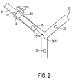
- Fig. 2 shows a detail of a module in which the calibration and test sites are included.
- the calibration opening 31 and the test opening 32 are formed in such a manner that when the instrument 20 is inserted into the relevant openings until it abuts against an abutment 43, the end 23 of the instrument 20 will be in the calibration site or the test site.
- the calibration site and the test site are situated in the same location in the module shown in the example, and the orientations of the instrument 20 in the calibration site and the test site enclose an angle of approximately 90° relative to one another.
- the functions of the test system are performed by the position measuring system with the computer 9 and the module 30.
- the LEDs or IREDs constituting the transmitter unit of the instrument are detachably mounted on the grip 42 of the instrument 20, for example by means of an elastic clamp 41.
- the grip 42 acts as the reference part and the end 23 is an example of the object part.
- Such a transmitter unit can be readily exchanged between different instruments without an own, fixed transmitter unit.
Landscapes
- Health & Medical Sciences (AREA)
- Surgery (AREA)
- Life Sciences & Earth Sciences (AREA)
- Engineering & Computer Science (AREA)
- Heart & Thoracic Surgery (AREA)
- Animal Behavior & Ethology (AREA)
- Veterinary Medicine (AREA)
- Biomedical Technology (AREA)
- Nuclear Medicine, Radiotherapy & Molecular Imaging (AREA)
- Medical Informatics (AREA)
- Molecular Biology (AREA)
- Public Health (AREA)
- General Health & Medical Sciences (AREA)
- Pathology (AREA)
- Oral & Maxillofacial Surgery (AREA)
- Robotics (AREA)
- Apparatus For Radiation Diagnosis (AREA)
- Length Measuring Devices By Optical Means (AREA)
- Manipulator (AREA)
Abstract
Claims (8)
- Système chirurgical guidé par image qui comprend :- un système de mesure de position (9, 10) pour mesurer la position d'un instrument (20),- un système de test (30, 10, 9) pour mesurer la position de l'instrument (20) en utilisant le système de mesure de position (9,10),- en mesurant une position d'étalonnage d'une partie de référence (42) de l'instrument (20) tandis qu'une partie objet (23) de l'instrument (20) est située dans un site d'étalonnage (33), où- le système chirurgical guidé par image comprend un site de test (34) et- le système de test (30, 10, 9) est aménagé pour- mesurer une position de test de la partie de référence (42) de l'instrument (20) tandis que la partie objet (23) de l'instrument (20) est située dans le site de test (34) et- comparer la position d'étalonnage mesurée à la position de test mesurée,caractérisé en ce que- un module (30) comprenant lesdits sites d'étalonnage et de test (33, 34) est conçu de telle sorte que
une orientation de la partie objet (23) par rapport à la partie de référence (42) tandis que la partie objet (23) est située dans le site d'étalonnage (33) dévie d'une orientation de la partie objet (23) par rapport à la partie de référence (42) tandis que la partie objet (23) est située dans le site de test (34). - Système chirurgical guidé par image selon la revendication 1, caractérisé en ce que :- le système de test (30, 10, 9) est aménagé pour mesurer des positions du site d'étalonnage (33) et/ou du site de test (34) au moyen du système de mesure de position (9, 10).
- Système chirurgical guidé par image selon la revendication 1, caractérisé en ce que :- le site d'étalonnage (33) et le site de test (34) coïncident essentiellement.
- Système chirurgical guidé par image selon la revendication 1, caractérisé en ce que :- l'orientation de la partie objet (23) par rapport à la partie de référence (42) tandis que la partie objet (23) est située dans le site d'étalonnage (33) est sensiblement perpendiculaire à l'orientation de la partie objet (23) par rapport à la partie de référence (42) tandis que la partie objet (23) est située dans le site de test (34).
- Système chirurgical guidé par image selon la revendication 1, caractérisé en ce que- la partie de référence (42) de l'instrument (20) est pourvue d'une unité de transmission (19) pour transmettre un signal de position qui représente la position de la partie de référence (42) et auquel le système de mesure de position (9, 10) est sensible.
- Système chirurgical guidé par image selon la revendication 5, caractérisé en ce que- l'unité de transmission (19) est raccordée de manière détachable à la partie de référence (42).
- Système chirurgical guidé par image selon la revendication 1, caractérisé en ce que- le système de test (30, 10, 9) est aménagé pour obtenir une précision de la mesure de l'instrument (20) sur la base de la position d'étalonnage mesurée et de la position de test mesurée.
- Système chirurgical guidé par image selon la revendication 7, caractérisé en ce que- le système de test (30, 10, 9) est aménagé pour obtenir des mesures respectives de l'instrument à partir de la position d'étalonnage mesurée et de la position de test mesurée, et pour reproduire une différence entre les mesures respectives.
Priority Applications (1)
| Application Number | Priority Date | Filing Date | Title |
|---|---|---|---|
| EP98924528A EP0929267B1 (fr) | 1997-07-03 | 1998-06-25 | Systeme de chirurgie guide par l'image |
Applications Claiming Priority (4)
| Application Number | Priority Date | Filing Date | Title |
|---|---|---|---|
| EP97202044 | 1997-07-03 | ||
| EP97202044 | 1997-07-03 | ||
| PCT/IB1998/000982 WO1999001078A2 (fr) | 1997-07-03 | 1998-06-25 | Systeme de chirurgie guide par l'image |
| EP98924528A EP0929267B1 (fr) | 1997-07-03 | 1998-06-25 | Systeme de chirurgie guide par l'image |
Publications (2)
| Publication Number | Publication Date |
|---|---|
| EP0929267A2 EP0929267A2 (fr) | 1999-07-21 |
| EP0929267B1 true EP0929267B1 (fr) | 2008-09-10 |
Family
ID=8228514
Family Applications (1)
| Application Number | Title | Priority Date | Filing Date |
|---|---|---|---|
| EP98924528A Expired - Lifetime EP0929267B1 (fr) | 1997-07-03 | 1998-06-25 | Systeme de chirurgie guide par l'image |
Country Status (5)
| Country | Link |
|---|---|
| US (1) | US6112113A (fr) |
| EP (1) | EP0929267B1 (fr) |
| JP (1) | JP4155344B2 (fr) |
| DE (1) | DE69839989D1 (fr) |
| WO (1) | WO1999001078A2 (fr) |
Families Citing this family (45)
| Publication number | Priority date | Publication date | Assignee | Title |
|---|---|---|---|---|
| ES2304794T3 (es) | 1998-06-22 | 2008-10-16 | Ao Technology Ag | Pareo de localizacion por medio de tornillos de localizacion. |
| WO2000039576A1 (fr) | 1998-12-23 | 2000-07-06 | Image Guided Technologies, Inc. | Sonde hybride 3-d localisee par des capteurs multiples |
| AU748703B2 (en) | 1999-03-17 | 2002-06-13 | Ao Technology Ag | Imaging and planning device for ligament graft placement |
| EP1171780A1 (fr) | 1999-04-20 | 2002-01-16 | Synthes Ag Chur | Dispositif permettant d'obtenir par voie percutanee des coordonnees tridimensionnelles a la surface d'un organe d'humain ou d'animal |
| DE19956814B4 (de) * | 1999-11-25 | 2004-07-15 | Brainlab Ag | Formerfassung von Behandlungsvorrichtungen |
| JP2001224595A (ja) * | 1999-12-08 | 2001-08-21 | Olympus Optical Co Ltd | 顕微鏡下手術用超音波プローブ |
| US7635390B1 (en) | 2000-01-14 | 2009-12-22 | Marctec, Llc | Joint replacement component having a modular articulating surface |
| US20010034530A1 (en) | 2000-01-27 | 2001-10-25 | Malackowski Donald W. | Surgery system |
| US6497134B1 (en) | 2000-03-15 | 2002-12-24 | Image Guided Technologies, Inc. | Calibration of an instrument |
| JP2003534035A (ja) * | 2000-03-15 | 2003-11-18 | オーソソフト インコーポレイテッド | コンピュータ支援手術器具の自動校正システム |
| US6511418B2 (en) * | 2000-03-30 | 2003-01-28 | The Board Of Trustees Of The Leland Stanford Junior University | Apparatus and method for calibrating and endoscope |
| FR2814669B1 (fr) * | 2000-09-29 | 2004-01-02 | Bertrand Lombard | Dispositif de naviguation chirurgicale |
| US20020156361A1 (en) * | 2000-10-19 | 2002-10-24 | Youri Popowski | Positioning template for implanting a substance into a patient |
| WO2002061371A1 (fr) * | 2001-01-30 | 2002-08-08 | Z-Kat, Inc. | Etalonneur d'instrument et systeme de suivi |
| US6584339B2 (en) | 2001-06-27 | 2003-06-24 | Vanderbilt University | Method and apparatus for collecting and processing physical space data for use while performing image-guided surgery |
| US7708741B1 (en) | 2001-08-28 | 2010-05-04 | Marctec, Llc | Method of preparing bones for knee replacement surgery |
| ES2225668T3 (es) * | 2002-03-01 | 2005-03-16 | Brainlab Ag | Lampara para sala de operadciones, que incluye un sistema de camaras para referenciacion tridimensional. |
| US7213598B2 (en) * | 2002-05-28 | 2007-05-08 | Brainlab Ag | Navigation-calibrating rotationally asymmetrical medical instruments or implants |
| ATE491403T1 (de) * | 2002-05-28 | 2011-01-15 | Brainlab Ag | Navigations-kalibrierung medizinischer instrumente bzw. implantate |
| US6892090B2 (en) * | 2002-08-19 | 2005-05-10 | Surgical Navigation Technologies, Inc. | Method and apparatus for virtual endoscopy |
| US7166114B2 (en) * | 2002-09-18 | 2007-01-23 | Stryker Leibinger Gmbh & Co Kg | Method and system for calibrating a surgical tool and adapter thereof |
| US7090639B2 (en) * | 2003-05-29 | 2006-08-15 | Biosense, Inc. | Ultrasound catheter calibration system |
| US7873400B2 (en) * | 2003-12-10 | 2011-01-18 | Stryker Leibinger Gmbh & Co. Kg. | Adapter for surgical navigation trackers |
| US7771436B2 (en) * | 2003-12-10 | 2010-08-10 | Stryker Leibinger Gmbh & Co. Kg. | Surgical navigation tracker, system and method |
| US8290570B2 (en) * | 2004-09-10 | 2012-10-16 | Stryker Leibinger Gmbh & Co., Kg | System for ad hoc tracking of an object |
| US8007448B2 (en) * | 2004-10-08 | 2011-08-30 | Stryker Leibinger Gmbh & Co. Kg. | System and method for performing arthroplasty of a joint and tracking a plumb line plane |
| US7623250B2 (en) * | 2005-02-04 | 2009-11-24 | Stryker Leibinger Gmbh & Co. Kg. | Enhanced shape characterization device and method |
| US20070179626A1 (en) * | 2005-11-30 | 2007-08-02 | De La Barrera Jose L M | Functional joint arthroplasty method |
| US8560047B2 (en) | 2006-06-16 | 2013-10-15 | Board Of Regents Of The University Of Nebraska | Method and apparatus for computer aided surgery |
| US8382765B2 (en) * | 2007-08-07 | 2013-02-26 | Stryker Leibinger Gmbh & Co. Kg. | Method of and system for planning a surgery |
| JP5540583B2 (ja) * | 2009-06-24 | 2014-07-02 | 富士ゼロックス株式会社 | 位置計測システム、位置計測用演算装置およびプログラム |
| US9498231B2 (en) | 2011-06-27 | 2016-11-22 | Board Of Regents Of The University Of Nebraska | On-board tool tracking system and methods of computer assisted surgery |
| JP6259757B2 (ja) | 2011-06-27 | 2018-01-10 | ボード オブ リージェンツ オブ ザ ユニバーシティ オブ ネブラスカ | コンピュータ支援手術の搭載器具追跡システム |
| CA3067299A1 (fr) | 2011-09-02 | 2013-03-07 | Stryker Corporation | Instrument chirurgical comprenant un boitier, un accessoire de coupe qui s'etend a partir du boitier et des actionneurs qui etablissent la position de l'accessoire de coupe par rapport au boitier |
| US9498182B2 (en) | 2012-05-22 | 2016-11-22 | Covidien Lp | Systems and methods for planning and navigation |
| US9439622B2 (en) | 2012-05-22 | 2016-09-13 | Covidien Lp | Surgical navigation system |
| US9439623B2 (en) | 2012-05-22 | 2016-09-13 | Covidien Lp | Surgical planning system and navigation system |
| US8750568B2 (en) | 2012-05-22 | 2014-06-10 | Covidien Lp | System and method for conformal ablation planning |
| US9439627B2 (en) | 2012-05-22 | 2016-09-13 | Covidien Lp | Planning system and navigation system for an ablation procedure |
| WO2014087289A2 (fr) * | 2012-12-06 | 2014-06-12 | Koninklijke Philips N.V. | Appareil d'étalonnage |
| US9888967B2 (en) * | 2012-12-31 | 2018-02-13 | Mako Surgical Corp. | Systems and methods for guiding a user during surgical planning |
| US10105149B2 (en) | 2013-03-15 | 2018-10-23 | Board Of Regents Of The University Of Nebraska | On-board tool tracking system and methods of computer assisted surgery |
| US10692240B2 (en) * | 2013-06-25 | 2020-06-23 | Varian Medical Systems, Inc. | Systems and methods for detecting a possible collision between an object and a patient in a medical procedure |
| EP3265010B1 (fr) * | 2015-03-05 | 2022-11-02 | Think Surgical, Inc. | Procédés pour positionner et suivre un axe d'outil |
| WO2020033947A1 (fr) | 2018-08-10 | 2020-02-13 | Covidien Lp | Systèmes de visualisation d'ablation |
Family Cites Families (9)
| Publication number | Priority date | Publication date | Assignee | Title |
|---|---|---|---|---|
| US5389101A (en) * | 1992-04-21 | 1995-02-14 | University Of Utah | Apparatus and method for photogrammetric surgical localization |
| US5309101A (en) * | 1993-01-08 | 1994-05-03 | General Electric Company | Magnetic resonance imaging in an inhomogeneous magnetic field |
| US6236875B1 (en) * | 1994-10-07 | 2001-05-22 | Surgical Navigation Technologies | Surgical navigation systems including reference and localization frames |
| US5549616A (en) * | 1993-11-02 | 1996-08-27 | Loma Linda University Medical Center | Vacuum-assisted stereotactic fixation system with patient-activated switch |
| US5695501A (en) * | 1994-09-30 | 1997-12-09 | Ohio Medical Instrument Company, Inc. | Apparatus for neurosurgical stereotactic procedures |
| US5891157A (en) * | 1994-09-30 | 1999-04-06 | Ohio Medical Instrument Company, Inc. | Apparatus for surgical stereotactic procedures |
| US5617857A (en) * | 1995-06-06 | 1997-04-08 | Image Guided Technologies, Inc. | Imaging system having interactive medical instruments and methods |
| WO1997029678A2 (fr) * | 1996-02-15 | 1997-08-21 | Biosense Inc. | Systeme de controle de l'etalonnage et de l'utilisation d'un catheter |
| US5921992A (en) * | 1997-04-11 | 1999-07-13 | Radionics, Inc. | Method and system for frameless tool calibration |
-
1998
- 1998-06-25 JP JP50678299A patent/JP4155344B2/ja not_active Expired - Lifetime
- 1998-06-25 DE DE69839989T patent/DE69839989D1/de not_active Expired - Lifetime
- 1998-06-25 WO PCT/IB1998/000982 patent/WO1999001078A2/fr active IP Right Grant
- 1998-06-25 EP EP98924528A patent/EP0929267B1/fr not_active Expired - Lifetime
- 1998-07-02 US US09/109,872 patent/US6112113A/en not_active Expired - Lifetime
Also Published As
| Publication number | Publication date |
|---|---|
| JP4155344B2 (ja) | 2008-09-24 |
| US6112113A (en) | 2000-08-29 |
| DE69839989D1 (de) | 2008-10-23 |
| WO1999001078A2 (fr) | 1999-01-14 |
| WO1999001078A3 (fr) | 1999-03-25 |
| JP2001500775A (ja) | 2001-01-23 |
| EP0929267A2 (fr) | 1999-07-21 |
Similar Documents
| Publication | Publication Date | Title |
|---|---|---|
| EP0929267B1 (fr) | Systeme de chirurgie guide par l'image | |
| US20230037993A1 (en) | Surgical instrument and method for detecting the position of a surgical instrument | |
| US6006127A (en) | Image-guided surgery system | |
| US5954648A (en) | Image guided surgery system | |
| RU2434600C2 (ru) | Хирургическая система, управляемая по изображениям | |
| US5904691A (en) | Trackable guide block | |
| JP4153305B2 (ja) | 器具較正器および追跡システム | |
| US6081741A (en) | Infrared surgical site locating device and method | |
| US6478802B2 (en) | Method and apparatus for display of an image guided drill bit | |
| EP2436333B1 (fr) | Système de navigation chirurgicale | |
| US4930525A (en) | Method for performing C.T. guided drainage and biopsy procedures | |
| JP6952696B2 (ja) | 医療ガイダンス装置 | |
| US20020032380A1 (en) | Medical probes with field transducers | |
| JP7367976B2 (ja) | 手術器具の自動検出のための検出システムおよび方法 | |
| JPH11188045A (ja) | ツール較正装置及び方法 | |
| JPH11509456A (ja) | 画像誘導手術システム | |
| JP4132006B2 (ja) | 外科用器具の精度を校正して検証する装置 | |
| US10939889B2 (en) | Optical shape sensing for fluoroscopic surgical navigation | |
| CN113303840A (zh) | 一种借助内窥镜的手术导航定位系统 | |
| US8067726B2 (en) | Universal instrument calibration system and method of use | |
| CN217525216U (zh) | 一种借助内窥镜的手术导航定位系统 | |
| EP0975272B1 (fr) | Systeme de chirurgie guide par l'image | |
| RU2771799C2 (ru) | Калибровка жесткого отоларингологического инструмента | |
| EP0832610A2 (fr) | Dispositif de guidage détectable pour instrument chirurgical | |
| EP3426178B1 (fr) | Système de navigation pour ponction, biopsie ou ablation comprenant un instrument en forme d'aiguille et un support de capteur amovible |
Legal Events
| Date | Code | Title | Description |
|---|---|---|---|
| PUAI | Public reference made under article 153(3) epc to a published international application that has entered the european phase |
Free format text: ORIGINAL CODE: 0009012 |
|
| 17P | Request for examination filed |
Effective date: 19990406 |
|
| AK | Designated contracting states |
Kind code of ref document: A2 Designated state(s): DE FR GB NL |
|
| 17Q | First examination report despatched |
Effective date: 20011102 |
|
| GRAH | Despatch of communication of intention to grant a patent |
Free format text: ORIGINAL CODE: EPIDOS IGRA |
|
| GRAS | Grant fee paid |
Free format text: ORIGINAL CODE: EPIDOSNIGR3 |
|
| GRAA | (expected) grant |
Free format text: ORIGINAL CODE: 0009210 |
|
| AK | Designated contracting states |
Kind code of ref document: B1 Designated state(s): DE FR GB NL |
|
| REG | Reference to a national code |
Ref country code: GB Ref legal event code: FG4D |
|
| REF | Corresponds to: |
Ref document number: 69839989 Country of ref document: DE Date of ref document: 20081023 Kind code of ref document: P |
|
| NLV1 | Nl: lapsed or annulled due to failure to fulfill the requirements of art. 29p and 29m of the patents act | ||
| PG25 | Lapsed in a contracting state [announced via postgrant information from national office to epo] |
Ref country code: NL Free format text: LAPSE BECAUSE OF FAILURE TO SUBMIT A TRANSLATION OF THE DESCRIPTION OR TO PAY THE FEE WITHIN THE PRESCRIBED TIME-LIMIT Effective date: 20080910 |
|
| PLBE | No opposition filed within time limit |
Free format text: ORIGINAL CODE: 0009261 |
|
| STAA | Information on the status of an ep patent application or granted ep patent |
Free format text: STATUS: NO OPPOSITION FILED WITHIN TIME LIMIT |
|
| 26N | No opposition filed |
Effective date: 20090611 |
|
| REG | Reference to a national code |
Ref country code: FR Ref legal event code: ST Effective date: 20100226 |
|
| PG25 | Lapsed in a contracting state [announced via postgrant information from national office to epo] |
Ref country code: FR Free format text: LAPSE BECAUSE OF NON-PAYMENT OF DUE FEES Effective date: 20090630 |
|
| REG | Reference to a national code |
Ref country code: DE Ref legal event code: R082 Ref document number: 69839989 Country of ref document: DE Representative=s name: MEISSNER, BOLTE & PARTNER GBR, DE |
|
| REG | Reference to a national code |
Ref country code: DE Ref legal event code: R082 Ref document number: 69839989 Country of ref document: DE Representative=s name: MEISSNER BOLTE PATENTANWAELTE RECHTSANWAELTE P, DE Effective date: 20140328 Ref country code: DE Ref legal event code: R082 Ref document number: 69839989 Country of ref document: DE Representative=s name: MEISSNER, BOLTE & PARTNER GBR, DE Effective date: 20140328 Ref country code: DE Ref legal event code: R081 Ref document number: 69839989 Country of ref document: DE Owner name: KONINKLIJKE PHILIPS N.V., NL Free format text: FORMER OWNER: KONINKLIJKE PHILIPS ELECTRONICS N.V., EINDHOVEN, NL Effective date: 20140328 |
|
| PGFP | Annual fee paid to national office [announced via postgrant information from national office to epo] |
Ref country code: GB Payment date: 20170630 Year of fee payment: 20 |
|
| PGFP | Annual fee paid to national office [announced via postgrant information from national office to epo] |
Ref country code: DE Payment date: 20170831 Year of fee payment: 20 |
|
| REG | Reference to a national code |
Ref country code: DE Ref legal event code: R071 Ref document number: 69839989 Country of ref document: DE |
|
| REG | Reference to a national code |
Ref country code: GB Ref legal event code: PE20 Expiry date: 20180624 |
|
| PG25 | Lapsed in a contracting state [announced via postgrant information from national office to epo] |
Ref country code: GB Free format text: LAPSE BECAUSE OF EXPIRATION OF PROTECTION Effective date: 20180624 |