EP0928097A2 - Méthode et appareil pour le montage et l'alignement des poinçons pour un appareil de composition - Google Patents
Méthode et appareil pour le montage et l'alignement des poinçons pour un appareil de composition Download PDFInfo
- Publication number
- EP0928097A2 EP0928097A2 EP98204326A EP98204326A EP0928097A2 EP 0928097 A2 EP0928097 A2 EP 0928097A2 EP 98204326 A EP98204326 A EP 98204326A EP 98204326 A EP98204326 A EP 98204326A EP 0928097 A2 EP0928097 A2 EP 0928097A2
- Authority
- EP
- European Patent Office
- Prior art keywords
- punch
- internal drum
- punch assembly
- carrier plate
- installing
- Prior art date
- Legal status (The legal status is an assumption and is not a legal conclusion. Google has not performed a legal analysis and makes no representation as to the accuracy of the status listed.)
- Withdrawn
Links
Images
Classifications
-
- H—ELECTRICITY
- H04—ELECTRIC COMMUNICATION TECHNIQUE
- H04N—PICTORIAL COMMUNICATION, e.g. TELEVISION
- H04N1/00—Scanning, transmission or reproduction of documents or the like, e.g. facsimile transmission; Details thereof
- H04N1/04—Scanning arrangements, i.e. arrangements for the displacement of active reading or reproducing elements relative to the original or reproducing medium, or vice versa
- H04N1/06—Scanning arrangements, i.e. arrangements for the displacement of active reading or reproducing elements relative to the original or reproducing medium, or vice versa using cylindrical picture-bearing surfaces, i.e. scanning a main-scanning line substantially perpendicular to the axis and lying in a curved cylindrical surface
- H04N1/08—Mechanisms for mounting or holding the sheet around the drum
- H04N1/083—Holding means
- H04N1/0873—Holding means for holding the sheet on the internal surface of the drum
-
- B—PERFORMING OPERATIONS; TRANSPORTING
- B41—PRINTING; LINING MACHINES; TYPEWRITERS; STAMPS
- B41B—MACHINES OR ACCESSORIES FOR MAKING, SETTING, OR DISTRIBUTING TYPE; TYPE; PHOTOGRAPHIC OR PHOTOELECTRIC COMPOSING DEVICES
- B41B21/00—Common details of photographic composing machines of the kinds covered in groups B41B17/00 and B41B19/00
- B41B21/32—Film carriers; Film-conveying or positioning devices
-
- H—ELECTRICITY
- H04—ELECTRIC COMMUNICATION TECHNIQUE
- H04N—PICTORIAL COMMUNICATION, e.g. TELEVISION
- H04N1/00—Scanning, transmission or reproduction of documents or the like, e.g. facsimile transmission; Details thereof
- H04N1/04—Scanning arrangements, i.e. arrangements for the displacement of active reading or reproducing elements relative to the original or reproducing medium, or vice versa
- H04N1/06—Scanning arrangements, i.e. arrangements for the displacement of active reading or reproducing elements relative to the original or reproducing medium, or vice versa using cylindrical picture-bearing surfaces, i.e. scanning a main-scanning line substantially perpendicular to the axis and lying in a curved cylindrical surface
- H04N1/08—Mechanisms for mounting or holding the sheet around the drum
- H04N1/0882—Registering or guiding means other than the holding means
-
- Y—GENERAL TAGGING OF NEW TECHNOLOGICAL DEVELOPMENTS; GENERAL TAGGING OF CROSS-SECTIONAL TECHNOLOGIES SPANNING OVER SEVERAL SECTIONS OF THE IPC; TECHNICAL SUBJECTS COVERED BY FORMER USPC CROSS-REFERENCE ART COLLECTIONS [XRACs] AND DIGESTS
- Y10—TECHNICAL SUBJECTS COVERED BY FORMER USPC
- Y10T—TECHNICAL SUBJECTS COVERED BY FORMER US CLASSIFICATION
- Y10T29/00—Metal working
- Y10T29/49—Method of mechanical manufacture
- Y10T29/49826—Assembling or joining
- Y10T29/49895—Associating parts by use of aligning means [e.g., use of a drift pin or a "fixture"]
-
- Y—GENERAL TAGGING OF NEW TECHNOLOGICAL DEVELOPMENTS; GENERAL TAGGING OF CROSS-SECTIONAL TECHNOLOGIES SPANNING OVER SEVERAL SECTIONS OF THE IPC; TECHNICAL SUBJECTS COVERED BY FORMER USPC CROSS-REFERENCE ART COLLECTIONS [XRACs] AND DIGESTS
- Y10—TECHNICAL SUBJECTS COVERED BY FORMER USPC
- Y10T—TECHNICAL SUBJECTS COVERED BY FORMER US CLASSIFICATION
- Y10T83/00—Cutting
- Y10T83/04—Processes
- Y10T83/0596—Cutting wall of hollow work
Definitions
- the present invention is in the field of imaging systems. More specifically, the present invention provides a method and apparatus for installing and aligning standard or custom ordered punches onto the internal drum of an imagesetter, platesetter, or other imaging system, at any field or customer location.
- the present invention provides a method and apparatus for installing punches onto an imaging system.
- the punches are accurately installed and aligned on a carrier plate at a manufacturing location, forming a punch assembly.
- the carrier plate includes a plurality of openings which are configured to mate with corresponding precision locator pins on the imaging system.
- the punch assembly is installed on the imaging system by inserting the precision locator pins through the plurality of openings in the carrier plate.
- the present invention provide a method for installing punches on an internal drum of an imaging system, comprising the steps of:
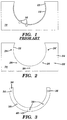
- FIG. 1 An end view of a prior art type internal drum 10, used in applications such as an imagesetter or platesetter, is illustrated in FIG. 1.
- the internal drum 10 includes a cylindrical imaging surface 12 for supporting a supply of recording media 14 during imaging.
- Imaging systems incorporating an internal drum are disclosed, for example, in U.S. Patent Nos. 5,598,739, 5,655,452, and 5,671,005, which are hereby incorporated by reference.
- the present invention obviates these and other disadvantages associated with the prior art, by providing a unique method and apparatus for accurately installing and aligning standard and custom ordered punches onto the internal drum of an imaging system at any field or customer location.
- FIG. 2 there is illustrated an end view of an internal drum 20 configured in accordance with a preferred embodiment of the present invention.
- the present invention is described hereinbelow with regard to the installation and alignment of side punches, it should be noted that the techniques of the present invention are also applicable to the installation and alignment of head, tail, and other types of internal punches commonly used in conjunction with an internal drum imaging system.
- the end 22 of the internal drum 20 onto which the side punches are to be installed is provided (e.g., machined) with a precision flat surface 24.
- At least two precision locator pins 26, 26', or other equivalent structures, are mounted onto the end 22 of the drum 20 and extend perpendicularly away (out of the page) from the flat surface 24.
- At least one mounting hole 28 is formed in the flat surface 24.
- the carrier plate 30 is shaped to conform to the curvature of the cylindrical imaging surface 32 of the internal drum 20, and has a precision flat inner surface (not shown) designed to mate against the flat surface 24 of the internal drum 20 when secured thereto.
- the carrier plate 30 includes an anchor hole 34 for receiving a first one of the locator pins 26, and a slot 36 for receiving the second of the locator pins 26'.
- the anchor hole 34 is sized to securely receive the locator pin 26.
- the slot 36 compensates for any positional shift of the second locator pin 26' due to dimensional changes in the carrier plate 30 (e.g., in response to variations in temperature).
- the carrier plate 30 is additionally provided with at least one mounting hole 38 which, when the carrier plate 30 is mounted on the locator pins 26, 26', are positioned to align with corresponding ones of the mounting holes 28.
- a mounting bolt 40 or the like, inserted through each pair of mounting holes 38, 28, is used to secure the carrier plate 30 against the flat surface 24 of the internal drum 20.
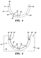
- a number of side punches 42 are installed along the inner radius of the carrier plate 30 prior to the attachment of the carrier plate 30 to the internal drum 20, thereby forming a punch assembly 44 as shown in FIG. 4.
- the specific locations of the side punches 42 are determined by the punch requirements of a customer.
- the side punches 42 are secured to the carrier plate 30 using bolts 46 or other suitable hardware.
- the side punches 42 are accurately installed and aligned along the internal radius of the drum 20 upon attachment of the plate assembly 44 to the end of the internal drum 20 as illustrated in FIG. 5.
- an imagesetter, platesetter, or other type of internal drum imaging system would be built without punches and shipped to a customer site.
- a standard or custom punch order indicating the desired location of the punches, and any other unique punch specifications (e.g., punch type, shape, size), is transmitted by the customer to the factory.
- the punch order is specified according to a standard format based on the location of the precision locator pins 26, 26'.
- the factory fabricates or assembles the required punch configuration on a carrier plate 30 using factory fixturing and alignment tooling.
- the completed punch assembly 44 is shipped directly to the customer site where it is attached to the internal drum 20. Because the punch assembly 44 is attached to the internal drum 20 using the precision locator pins 26, 26', no alignment is required at the customer site.
- a customer may order a plurality of punch assemblies 44, each having a different punch specification (e.g., punch location, punch type), and interchangeably install the punch assemblies onto the precision locator pins 26, 26' on the internal drum 20 while on-site.
- a punch specification e.g., punch location, punch type
- the entire imaging unit must be shipped back to the factory in order to install and align a different set of punches on the internal drum.
- the present invention increases the productivity and functionality of internal drum imaging systems by simplifying the punch installation process.
- the carrier plate may include a plurality of pins which are configured to be inserted into corresponding precision locator openings formed in the internal drum.
Landscapes
- Engineering & Computer Science (AREA)
- Multimedia (AREA)
- Signal Processing (AREA)
- Exposure And Positioning Against Photoresist Photosensitive Materials (AREA)
- Perforating, Stamping-Out Or Severing By Means Other Than Cutting (AREA)
Applications Claiming Priority (2)
| Application Number | Priority Date | Filing Date | Title |
|---|---|---|---|
| US916 | 1997-12-30 | ||
| US09/000,916 US5953807A (en) | 1997-12-30 | 1997-12-30 | Method for installing and aligning punches in an imaging system |
Publications (2)
| Publication Number | Publication Date |
|---|---|
| EP0928097A2 true EP0928097A2 (fr) | 1999-07-07 |
| EP0928097A3 EP0928097A3 (fr) | 2000-07-19 |
Family
ID=21693556
Family Applications (1)
| Application Number | Title | Priority Date | Filing Date |
|---|---|---|---|
| EP19980204326 Withdrawn EP0928097A3 (fr) | 1997-12-30 | 1998-12-17 | Méthode et appareil pour le montage et l'alignement des poinçons pour un appareil de composition |
Country Status (3)
| Country | Link |
|---|---|
| US (1) | US5953807A (fr) |
| EP (1) | EP0928097A3 (fr) |
| JP (1) | JPH11254394A (fr) |
Families Citing this family (4)
| Publication number | Priority date | Publication date | Assignee | Title |
|---|---|---|---|---|
| US6233038B1 (en) * | 1997-06-04 | 2001-05-15 | Agfa Corporation | Imaging system with integral punch mechanism |
| US6470777B2 (en) * | 1999-01-29 | 2002-10-29 | Agfa Corporation | Low profile side punch for internal drum imagesetter |
| US6173634B1 (en) * | 1999-03-19 | 2001-01-16 | Agfa Corporation | Method and apparatus for collecting and removing punch chaff from an imaging system |
| US7866242B1 (en) * | 2002-04-19 | 2011-01-11 | Harris K Michael | Noise dampener hub assembly for a circular saw |
Family Cites Families (5)
| Publication number | Priority date | Publication date | Assignee | Title |
|---|---|---|---|---|
| US4488716A (en) * | 1982-06-02 | 1984-12-18 | Crosfield Data Systems | Method of feeding material to and receiving it from a scanning system |
| US4566573A (en) * | 1982-12-15 | 1986-01-28 | Dana Corporation | Pressure plate strap drive apparatus and method |
| IL106243A (en) * | 1993-07-05 | 1996-01-31 | Scitex Corp Ltd | Inner beach type printer for printing plates |
| JPH0720757U (ja) * | 1993-09-06 | 1995-04-11 | 大日本スクリーン製造株式会社 | ドラム型走査装置用シート保持装置 |
| JP2928078B2 (ja) * | 1994-02-10 | 1999-07-28 | 大日本スクリーン製造株式会社 | 円筒内面走査装置に於ける穿孔装置 |
-
1997
- 1997-12-30 US US09/000,916 patent/US5953807A/en not_active Expired - Fee Related
-
1998
- 1998-12-17 EP EP19980204326 patent/EP0928097A3/fr not_active Withdrawn
- 1998-12-25 JP JP37004698A patent/JPH11254394A/ja active Pending
Also Published As
| Publication number | Publication date |
|---|---|
| JPH11254394A (ja) | 1999-09-21 |
| EP0928097A3 (fr) | 2000-07-19 |
| US5953807A (en) | 1999-09-21 |
Similar Documents
| Publication | Publication Date | Title |
|---|---|---|
| US6317980B2 (en) | Laser jigging system for assembly of trusses and method of use | |
| US5552857A (en) | Multicolor image forming apparatus | |
| US6016752A (en) | Print image positioning | |
| US4134632A (en) | Attaching means for circuit card connectors | |
| US5953807A (en) | Method for installing and aligning punches in an imaging system | |
| US7971769B2 (en) | Quick change over tooling for a welder | |
| US5379671A (en) | Magnetic saddle for non-magnetic die-cutting cylinders | |
| JPH03205678A (ja) | 精密な取付基準を備えたシート状金属ハウジングを提供する方法 | |
| US20020011384A1 (en) | Converter arrangement for modular motor | |
| US5996206A (en) | Method and apparatus for installing and aligning punches in an imaging system | |
| US8555475B2 (en) | Vehicle fixture with alignment target | |
| US5597259A (en) | Plate assembly | |
| CN219790309U (zh) | 一种前端模块与车身的连接结构及汽车 | |
| EP0957388A1 (fr) | Technique d'assemblage de précision utilisant un appareil d'alignement et l'assemblage ainsi formé | |
| EP0368348B1 (fr) | Gabarit pour poinçonneuse | |
| US4528573A (en) | Optical print head with removable mounting | |
| CN114264272B (zh) | 一种标定支架及标定系统 | |
| US5784964A (en) | Machine frame and method of manufacture thereof | |
| EP4290850A1 (fr) | Procédé d'assemblage d'un dispositif optique et dispositif optique assemblé selon celui-ci | |
| US6119556A (en) | Combination precision punch assembly and guide/matrix assembly and method of precision installation of a punch set | |
| JP3358358B2 (ja) | 移動機器担持装置 | |
| GB2449939A (en) | Method of manufacturing a printhead support | |
| GB2071212A (en) | A device for mounting brake cylinders on axle beams of vehicles | |
| US20020002829A1 (en) | Cryostat,cryostat positioning metho,and cryostat alignment set | |
| US5323209A (en) | Apparatus for precision alignment of plates used in two-sided contact printing |
Legal Events
| Date | Code | Title | Description |
|---|---|---|---|
| PUAI | Public reference made under article 153(3) epc to a published international application that has entered the european phase |
Free format text: ORIGINAL CODE: 0009012 |
|
| AK | Designated contracting states |
Kind code of ref document: A2 Designated state(s): DE FR GB |
|
| AX | Request for extension of the european patent |
Free format text: AL;LT;LV;MK;RO;SI |
|
| RAP1 | Party data changed (applicant data changed or rights of an application transferred) |
Owner name: AGFA CORPORATION |
|
| PUAL | Search report despatched |
Free format text: ORIGINAL CODE: 0009013 |
|
| AK | Designated contracting states |
Kind code of ref document: A3 Designated state(s): AT BE CH CY DE DK ES FI FR GB GR IE IT LI LU MC NL PT SE |
|
| AX | Request for extension of the european patent |
Free format text: AL;LT;LV;MK;RO;SI |
|
| RIC1 | Information provided on ipc code assigned before grant |
Free format text: 7H 04N 1/053 A, 7H 04N 1/06 B, 7H 04N 1/08 B, 7H 04N 1/00 B |
|
| 17P | Request for examination filed |
Effective date: 20010119 |
|
| AKX | Designation fees paid |
Free format text: DE FR GB |
|
| STAA | Information on the status of an ep patent application or granted ep patent |
Free format text: STATUS: THE APPLICATION HAS BEEN WITHDRAWN |
|
| 18W | Application withdrawn |
Effective date: 20040320 |