EP0928037B1 - Batterieanordnung - Google Patents
Batterieanordnung Download PDFInfo
- Publication number
- EP0928037B1 EP0928037B1 EP98904394A EP98904394A EP0928037B1 EP 0928037 B1 EP0928037 B1 EP 0928037B1 EP 98904394 A EP98904394 A EP 98904394A EP 98904394 A EP98904394 A EP 98904394A EP 0928037 B1 EP0928037 B1 EP 0928037B1
- Authority
- EP
- European Patent Office
- Prior art keywords
- connection member
- circuit board
- battery device
- flat connection
- battery
- Prior art date
- Legal status (The legal status is an assumption and is not a legal conclusion. Google has not performed a legal analysis and makes no representation as to the accuracy of the status listed.)
- Expired - Lifetime
Links
Images


Classifications
-
- H—ELECTRICITY
- H01—ELECTRIC ELEMENTS
- H01M—PROCESSES OR MEANS, e.g. BATTERIES, FOR THE DIRECT CONVERSION OF CHEMICAL ENERGY INTO ELECTRICAL ENERGY
- H01M10/00—Secondary cells; Manufacture thereof
- H01M10/04—Construction or manufacture in general
- H01M10/0413—Large-sized flat cells or batteries for motive or stationary systems with plate-like electrodes
-
- H—ELECTRICITY
- H01—ELECTRIC ELEMENTS
- H01M—PROCESSES OR MEANS, e.g. BATTERIES, FOR THE DIRECT CONVERSION OF CHEMICAL ENERGY INTO ELECTRICAL ENERGY
- H01M10/00—Secondary cells; Manufacture thereof
- H01M10/42—Methods or arrangements for servicing or maintenance of secondary cells or secondary half-cells
- H01M10/425—Structural combination with electronic components, e.g. electronic circuits integrated to the outside of the casing
- H01M10/4257—Smart batteries, e.g. electronic circuits inside the housing of the cells or batteries
-
- H—ELECTRICITY
- H01—ELECTRIC ELEMENTS
- H01M—PROCESSES OR MEANS, e.g. BATTERIES, FOR THE DIRECT CONVERSION OF CHEMICAL ENERGY INTO ELECTRICAL ENERGY
- H01M10/00—Secondary cells; Manufacture thereof
- H01M10/04—Construction or manufacture in general
- H01M10/0468—Compression means for stacks of electrodes and separators
-
- H—ELECTRICITY
- H01—ELECTRIC ELEMENTS
- H01M—PROCESSES OR MEANS, e.g. BATTERIES, FOR THE DIRECT CONVERSION OF CHEMICAL ENERGY INTO ELECTRICAL ENERGY
- H01M10/00—Secondary cells; Manufacture thereof
- H01M10/05—Accumulators with non-aqueous electrolyte
- H01M10/052—Li-accumulators
- H01M10/0525—Rocking-chair batteries, i.e. batteries with lithium insertion or intercalation in both electrodes; Lithium-ion batteries
-
- H—ELECTRICITY
- H01—ELECTRIC ELEMENTS
- H01M—PROCESSES OR MEANS, e.g. BATTERIES, FOR THE DIRECT CONVERSION OF CHEMICAL ENERGY INTO ELECTRICAL ENERGY
- H01M10/00—Secondary cells; Manufacture thereof
- H01M10/42—Methods or arrangements for servicing or maintenance of secondary cells or secondary half-cells
- H01M10/425—Structural combination with electronic components, e.g. electronic circuits integrated to the outside of the casing
-
- H—ELECTRICITY
- H01—ELECTRIC ELEMENTS
- H01M—PROCESSES OR MEANS, e.g. BATTERIES, FOR THE DIRECT CONVERSION OF CHEMICAL ENERGY INTO ELECTRICAL ENERGY
- H01M10/00—Secondary cells; Manufacture thereof
- H01M10/42—Methods or arrangements for servicing or maintenance of secondary cells or secondary half-cells
- H01M10/48—Accumulators combined with arrangements for measuring, testing or indicating the condition of cells, e.g. the level or density of the electrolyte
-
- H—ELECTRICITY
- H01—ELECTRIC ELEMENTS
- H01M—PROCESSES OR MEANS, e.g. BATTERIES, FOR THE DIRECT CONVERSION OF CHEMICAL ENERGY INTO ELECTRICAL ENERGY
- H01M50/00—Constructional details or processes of manufacture of the non-active parts of electrochemical cells other than fuel cells, e.g. hybrid cells
- H01M50/50—Current conducting connections for cells or batteries
-
- H—ELECTRICITY
- H01—ELECTRIC ELEMENTS
- H01M—PROCESSES OR MEANS, e.g. BATTERIES, FOR THE DIRECT CONVERSION OF CHEMICAL ENERGY INTO ELECTRICAL ENERGY
- H01M6/00—Primary cells; Manufacture thereof
- H01M6/50—Methods or arrangements for servicing or maintenance, e.g. for maintaining operating temperature
- H01M6/5044—Cells or batteries structurally combined with cell condition indicating means
-
- Y—GENERAL TAGGING OF NEW TECHNOLOGICAL DEVELOPMENTS; GENERAL TAGGING OF CROSS-SECTIONAL TECHNOLOGIES SPANNING OVER SEVERAL SECTIONS OF THE IPC; TECHNICAL SUBJECTS COVERED BY FORMER USPC CROSS-REFERENCE ART COLLECTIONS [XRACs] AND DIGESTS
- Y02—TECHNOLOGIES OR APPLICATIONS FOR MITIGATION OR ADAPTATION AGAINST CLIMATE CHANGE
- Y02E—REDUCTION OF GREENHOUSE GAS [GHG] EMISSIONS, RELATED TO ENERGY GENERATION, TRANSMISSION OR DISTRIBUTION
- Y02E60/00—Enabling technologies; Technologies with a potential or indirect contribution to GHG emissions mitigation
- Y02E60/10—Energy storage using batteries
-
- Y—GENERAL TAGGING OF NEW TECHNOLOGICAL DEVELOPMENTS; GENERAL TAGGING OF CROSS-SECTIONAL TECHNOLOGIES SPANNING OVER SEVERAL SECTIONS OF THE IPC; TECHNICAL SUBJECTS COVERED BY FORMER USPC CROSS-REFERENCE ART COLLECTIONS [XRACs] AND DIGESTS
- Y02—TECHNOLOGIES OR APPLICATIONS FOR MITIGATION OR ADAPTATION AGAINST CLIMATE CHANGE
- Y02P—CLIMATE CHANGE MITIGATION TECHNOLOGIES IN THE PRODUCTION OR PROCESSING OF GOODS
- Y02P70/00—Climate change mitigation technologies in the production process for final industrial or consumer products
- Y02P70/50—Manufacturing or production processes characterised by the final manufactured product
Definitions
- the present invention relates to battery devices. More particularly, the invention relates to a battery device including a lithium ion battery and a protection circuit board.
- lithium ion battery a secondary battery (may be hereinafter called merely “lithium ion battery”) that utilizes for its negative pole a material capable of being doped with and/or de-doped of lithium or lithium ions.
- This lithium ion battery which is high in power voltage and light in weight with suppressed self-discharge characteristics, has being placed into practical applications.
- the secondary battery of this kind has a characteristic that its electrode member experiences repeated expansion and contraction during charge and discharge of electricity. Under such a situation, various considerations have been made so far, as to how is solved the technical problem caused by expansion and contraction in the electrode material.
- Japanese Patent Laying-open No. H7-134984 [H01M 4/02, 4/58, 10/40] laid open to public on May 23, 1996, wherein a cylindrical secondary battery is structured by an electrode body in a spiral form so that the pressure exerted between the positive and negative electrodes are moderated even where thermal expansion in volume is caused in the electrode material to a full extent.
- Japanese Patent Laying-open No. H7-220754 [10/38, 10/38] laid open to public on August 18, 1996 proposes that an electrode body is structured by a layered body bundled by a thermally-contractable tube to absorb volumetric expansion caused upon electricity charging and discharging, thereby preventing the layered body from being deformed.
- the latter prior art further includes a resilient ring between the vessel and the lid or a corrugated portion in the vessel itself so that the electrode body is allowed to expand and contract, thus maintaining the form of the layered body.
- the lithium ion batteries as above often have a protection circuit to suppress the battery from going into overworking.
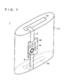
- a protection circuit is usually arranged directly on the battery as shown in Figure 1 due to the requirement to reduce the size and weight of the above-mentioned electronic appliances, thus achieving space savings.
- FIG. 1 a prior art battery device 1, which includes a lithium ion battery 12 having a layered body (not shown) in a flattened cylindrical form.
- This lithium ion battery 12 has a positive pole lead 14 exposed in a top surface and a negative pole lead 16 exposed in a bottom surface.
- a circuit board 20 built with a protection circuit 18 is arranged in contact with a side surface of the battery 12.
- the circuit board 20 has connection strips 2 and 4 electrically connected to the protection circuit 18. These connection strips 2 and 4 are formed, for example, by nickel thin sheets and electrically connected respectively to the positive pole lead 14 and the negative pole lead 16.
- the use of the lithium ion battery 1 results in repeated expansion and contraction in the layered body (not shown), as stated before. There is, however, no expansion and contraction in the circuit board 20 and the connection strips 2 and 4. As a result, stresses are applied to these parts. If such stresses be applied to structurally weak portions, such as the points fixing connection strips 2 and 4 on the circuit board 20, or to the circuit board 20 itself, there may be cases that cracks occur in circuit parts such as the protection circuit 18 or the circuit board 20.
- a battery device comprises: a lithium ion battery having a positive pole and a negative pole formed of a polymer material to effect electricity charge and discharge due to lithium ions; a circuit board arranged on an outer surface of the lithium ion battery; a first flat connection member which connects between the circuit board and the positive pole; a second flat connection member which connects between the circuit board and the negative pole; and a length varying means provided in association with at least one of the first flat connection member and the second flat connection member to vary at least one of a first connection length between the circuit board and the positive pole and a second connection length between the circuit board and the negative pole.
- connection length Even if there is a variation in the connection length between at least one of the positive and negative poles of the lithium ion battery and the circuit board due to expansion or contraction caused by charging or discharging the lithium ion battery, the variation in the connection length is absorbed by the length varying means provided in association with the first connection member/second connection member.
- the length varying means provided in association with at least one of the first connection member and the second connection member enables the connection member to be relieved of stresses acting thereon. This eliminates the necessity of using specially-designed parts or increasing the part rigidity, thus reducing cost without hindering against size and weight reductions in the battery device.
- the length varying means includes an expandable/contractible portion formed in at least one of the first connection member and the second connection member.
- This expandable/contractible portion includes a easily deformable portion. It can be considered that the easily deformable portion is formed by a plurality of partial cuts or a curved portion formed in at least one of the first connection member and the second connection member.
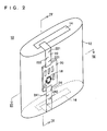
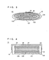
- the battery device 10 includes a lithium ion battery 12 structured as shown in Figure 3 and Figure 4.
- the lithium ion battery 12 has a structure basically similar to that described, for example, in Japanese Patent Laying-Open No. H7-134984 mentioned before. That is, the lithium ion battery 12 has a negative pole 121 formed by applying a negative-pole compound mixture based on a carbon-containing material to opposite surfaces of a strip-formed copper foil and then curing the same, a positive pole 122 formed by applying a positive-pole compound mixture based on LiCoO 2 to opposite surfaces of a strip-formed aluminum foil and then curing the same, and a separator formed by a polypropylene film with fine pores.
- These negative pole 121, the separator 123, the positive pole 122 and the separator 123 are layered in this order, and spirally wound into a flattened cylindrical form.
- This layered body is provided at its top surface with a positive-pole lead 14 and at its back surface with a negative-pole lead 16, which are respectively connected to the positive pole 122 and the negative pole 121.
- the layered body is entirely sealed by an insulating sheet 124 with flexibility so that only the positive-pole lead 14 and negative-pole lead 16 are exposed.
- a circuit board 20 formed with a protection circuit 18 is provided in contact with a side surface of the layered body.
- the circuit board 20 is fixed with connection strips 22 and 24 electrically connected to the protection circuit 18.
- the connection strips 22 and 24 are formed, for example, by nickel thin sheets (strips), and electrically connected to the respective positive-pole lead 14 and negative-pole lead 16.
- connection strips 22 and 24 have partial cuts 221, 222 and 241, 242. These partial cuts 221, 222 and 241, 242 constitute a length varying means which allows variation in the connection length.
- the connection length refers to a length of the connection strip 22 that extends between the circuit board 20 and the positive-pole lead 14, or a length of the connection strip 24 between the positive-pole lead 16 and the circuit board 20, wherein these connection strips 22 and 24 are laid, without looseness, on along an outer shape of the layered body, or the lithium ion battery 12.
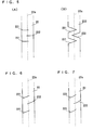
- Figure 5 is a plan view showing part of the connection strip 22 in this embodiment, wherein it should be noted that the other one of the connection strips may be structured in the similar manner.
- a plurality of partial cuts 121 are formed in a direction transverse a lengthwise direction of the connection strip 22, that is, they are formed in plurality of number extending in a width direction.
- the partial cut 221 at one widthwise side portion of the connection strip 22 extends from one end edge of the connection strip 22 to a point beyond a center line 22a of the connection strip 22, while the partial cut 222 in the other widthwise side portion extends from the other end edge to a point beyond the center line 22a of the connection strip 22. That is, these partial cuts 221 and 222 are alternately formed from the respective end edges of the connection strip 22 to points beyond the center line 22a.
- the partial cuts 221 and 222 are allowed to open lengthening the connection strip 22 in the lengthwise direction. That is, the partial cuts 221 and 222 are opened and closed depending upon the change of the connection length. This allows the length of the connection strip 22 to be varied in the lengthwise direction, thereby absorbing an corresponding variation amount in the connection length.
- connection strip 22 it is possible to determine a length variation in the lengthwise direction of the connection strip 22 by determining how long the above-stated partial cuts 221 and 222 are formed to a point beyond the center line 22a of the connection strip 22.
- the lengthwise length variation can also be increased by increasing the number of the partial cuts 221 and 222.
- the partial cuts 221 and 222 may be formed to extend obliquely relative to the lengthwise direction (and the width direction) of the connection strip 22, or formed in a curved shape. That is, the partial cuts 221, 222 and 241, 242 may be in any form provided that they are formed extending continuously from the respective end edges to a point beyond the center line of the connection strips 22 and 24. Accordingly, it is possible to provide them in a cut-out form in place of partial cuts. Where employing cut-outs, their forms may be arbitrary provided that the cut-outs are formed to a point beyond the center line of the connection strip 22, 24.
- partial cuts or cut-outs may be formed in a reshaping process after once forming connection strips 22 and 24, or formed simultaneous with the formation of the connection strips 22 and 24.
- FIG 8 is an illustrative view of a battery structure as viewed from a side, showing another embodiment of the present invention.
- connection strips 22 and 24 are provided extending along an outer shape of the battery 12, or the layered body, to connect between the circuit board 20 and the positive-pole lead 14 or negative-pole lead 16.
- the connection strips 22 and 24 are respectively formed with curved portions 223 and 243.
- One connection strip 24, representative of these two connection strips 22 and 24, is illustrated in Figure 9.
- This connection strip 24 includes a first portion 24a extending along a side surface of the battery 12 and a second portion 24b along a back surface of the battery 12, wherein the curved portion 243 is formed connecting between the first portion 24a and the second portion 24b.
- the curved portion 243 is formed such that one part in the connection strip 24 projects at its entire width in one direction (outwardly) to form a bend portion.
- connection length between the positive-pole lead 14 or negative-pole lead 16 and the circuit board 20 of the battery 12 is increased by expansion of the layered body or the like, the connection strips 22 and 24 experience tensions in the lengthwise direction. Thereupon the curved portions 223 and 243 are allowed to expand in the lengthwise direction, increasing the length of the connection strips 22, 24 corresponding to the increase in the connection length.
- connection strips 22 and 24 To fix the connection strips 22 and 24 onto the outer surface of the battery 12, there is a necessity to bend them in a manner extending along the outer shape of the battery 12.
- the curved portions 223 and 243 if previously formed at the bend portions of the connection strips 22 and 24 as shown in Figure 8 and Figure 9, facilitate the strips to be bent extending along the outer surface of the battery 12.
- the width-narrowed portion has a decreased strength. Accordingly, the curved portion 223 is readily expanded when a tensile force is applied to the connection strip 22. This reduces loads imparted to other portions than the curved portion 223 of the connection strip 22.
- the width was narrowed at the curved portion 223, it is also possible to reduce the strength of the curved portion 223 (243) by reducing the thickness at the curved portion 223 (243) of the connection strip 22 (24). This also makes the curved portion 223 (243) be deformed.
- all the above embodiments can absorb variation in the connection length between the circuit board 20 and the positive-pole lead 14 or the negative-pole lead 16 if partial cuts or cut-outs or curved portions are formed expandable or deformable in at least one of the connection strips 22 and 24. It is therefore possible to relax stresses caused due to the expansion and contraction of the battery 12 (layered body).
- the battery device 10 as embodied has a circuit configuration as shown in Figure 11. That is, this battery device 10 has a function to supply power from the lithium ion battery 12 to a battery-driven device (not shown) through a battery pack terminals.
- the positive pole and the negative pole of the lithium ion battery 12 are connected to the circuit board via the connection strips 22 and 24.
- the circuit board is formed thereon with a protection circuit 18 including a control IC 18a, such as "BA3153FV" made by Rohm Co., Ltd. and a switch 18b.
- the control IC 18a monitors voltage and/or current of the lithium ion battery 12.
- the control IC turns off the switch 18b depending upon the voltage/current when there is an over-current flowing or a voltage drop below a given value. Due to this, the power supply through the battery pack terminals is shut off. Also, the control IC 18a, during electricity charging, turns off the switch 18b based on the voltage/current when an over-current flows or the voltage is increased above a given value. Therefore, the supply of charging power through the battery pack terminal to the lithium ion battery 12 is shut off.
Landscapes
- Engineering & Computer Science (AREA)
- Chemical & Material Sciences (AREA)
- Manufacturing & Machinery (AREA)
- Chemical Kinetics & Catalysis (AREA)
- Electrochemistry (AREA)
- General Chemical & Material Sciences (AREA)
- Microelectronics & Electronic Packaging (AREA)
- Materials Engineering (AREA)
- Connection Of Batteries Or Terminals (AREA)
- Secondary Cells (AREA)
- Battery Mounting, Suspending (AREA)
Claims (9)
- Batterievorrichtung, aufweisend:eine Lithium-Ionen-Batterie (12), die einen positiven Pol (14) und einen negativen Pol (16) aufweist, der aus einem Polymermaterial so aufgebaut ist, dass bedingt durch Lithium-Ionen ein elektrisches Laden und Entladen bewirkt wird;eine Schaltungsplatine (20), die auf einer Außenfläche der Lithium-Ionen-Batterie angeordnet ist;ein erstes ebenes Verbindungselement (2), das zwischen der Schaltungsplatine (20) und dem positiven Pol (14) angeschlossen ist;ein zweites ebenes Verbindungselement (4), das zwischen der Schaltungsplatine (20) und dem negativen Pol (16) angeschlossen ist; undeine Längenveränderungseinrichtung, die in Verbindung mit dem ersten ebenen Verbindungselement (2) und/oder dem zweiten ebenen Verbindungselement (4) vorgesehen ist, um eine erste Verbindungslänge zwischen der Schaltungsplatine (20) und dem positiven Pol (14) und/oder eine zweite Verbindungslänge zwischen der Schaltungsplatine (20) und dem negativen Pol (16) zu verändern.
- Batterievorrichtung nach Anspruch 1, bei der die Längenveränderungseinrichtung einen ausdehnbaren/zusammenziehbaren Abschnitt beinhaltet, der in dem ersten ebenen Verbindungselement (2) und/oder dem zweiten ebenen Verbindungselement (4) ausgebildet ist.
- Batterievorrichtung nach Anspruch 2, bei welcher der ausdehnbare/zusammenziehbare Abschnitt einen ohne Weiteres verformbaren Abschnitt beinhaltet.
- Batterievorrichtung nach Anspruch 3, bei der das erste ebene Verbindungselement (2) und/oder das zweite ebene Verbindungselement (4) ein Streifenelement (22) mit vorbestimmter Breite ist und der ohne Weiteres verformbare Abschnitt eine Mehrzahl von partiellen Schnitten (221, 222) beinhaltet, die jeweils so ausgebildet sind dass sie sich von einem seitlichen Ende des Streifenelementes aus in Breitenrichtung erstrecken.
- Batterievorrichtung nach Anspruch 4, bei der die Mehrzahl von partiellen Schnitten (221, 222) sich von dem seitlichen Ende zu einem Punkt jenseits einer in Breitenrichtung gesehenen Mitte des Streifenelementes (22) erstrecken.
- Batterievorrichtung nach Anspruch 4 oder 5, bei welcher die Mehrzahl von partiellen Schnitten (221, 222) erste partielle Schnitte (221) und zweite partielle Schnitte (222) beinhaltet, die jeweils in seitlichen Abschnitten des Streifenelementes (22) ausgebildet sind.
- Batterievorrichtung nach Anspruch 6, bei welcher die ersten partiellen Schnitte (221) und die zweiten partiellen Schnitte (222) abwechselnd bezogen auf eine Längsrichtung (22a) des Streifenelementes (22) ausgebildet sind.
- Batterievorrichtung nach Anspruch 3, bei welcher der verformbare Abschnitt einen gekrümmten Abschnitt (223) beinhaltet, der in dem ersten ebenen Verbindungselement (22) und/oder dem zweiten ebenen Verbindungselement (24) ausgebildet ist.
- Batterievorrichtung nach Anspruch 8, bei welcher das erste ebene Verbindungselement (22) und/oder das zweite ebene Verbindungselement (24) einen geknickten Abschnitt beinhalten, bei dem die Knickung in einer Weise vorliegt, dass sie sich entlang einer Außenfläche der Lithium-Ionen-Batterie (12) erstreckt, und der gekrümmte Abschnitt (223, 243) an dem geknickten Abschnitt ausgebildet ist.
Applications Claiming Priority (3)
| Application Number | Priority Date | Filing Date | Title |
|---|---|---|---|
| JP9041757A JPH10241736A (ja) | 1997-02-26 | 1997-02-26 | 電池構造 |
| JP4175797 | 1997-02-26 | ||
| PCT/JP1998/000697 WO1998038689A1 (fr) | 1997-02-26 | 1998-02-18 | Ensemble pile |
Publications (3)
| Publication Number | Publication Date |
|---|---|
| EP0928037A1 EP0928037A1 (de) | 1999-07-07 |
| EP0928037A4 EP0928037A4 (de) | 2004-10-13 |
| EP0928037B1 true EP0928037B1 (de) | 2007-05-16 |
Family
ID=12617294
Family Applications (1)
| Application Number | Title | Priority Date | Filing Date |
|---|---|---|---|
| EP98904394A Expired - Lifetime EP0928037B1 (de) | 1997-02-26 | 1998-02-18 | Batterieanordnung |
Country Status (8)
| Country | Link |
|---|---|
| US (1) | US6117576A (de) |
| EP (1) | EP0928037B1 (de) |
| JP (1) | JPH10241736A (de) |
| KR (1) | KR100511375B1 (de) |
| CN (1) | CN100334773C (de) |
| DE (1) | DE69837782T2 (de) |
| TW (1) | TW364665U (de) |
| WO (1) | WO1998038689A1 (de) |
Families Citing this family (28)
| Publication number | Priority date | Publication date | Assignee | Title |
|---|---|---|---|---|
| JP4701464B2 (ja) * | 1998-12-04 | 2011-06-15 | 株式会社Gsユアサ | 電池 |
| JP3899499B2 (ja) * | 1998-11-18 | 2007-03-28 | ソニー株式会社 | 非水電解質電池 |
| JP4154633B2 (ja) * | 1999-03-12 | 2008-09-24 | ソニー株式会社 | 非水電解質電池 |
| EP1093178A4 (de) * | 1999-03-30 | 2007-12-05 | Matsushita Electric Industrial Co Ltd | Wieder aufladbare batterie mit schutzschaltung |
| US6337154B1 (en) * | 1999-09-24 | 2002-01-08 | Electrofuel Inc. | Battery box with a metal plastic laminate end |
| JP4494713B2 (ja) | 2001-12-04 | 2010-06-30 | パナソニック株式会社 | 電池パック |
| JP4440548B2 (ja) * | 2002-02-13 | 2010-03-24 | パナソニック株式会社 | 電池とその製造方法 |
| US7429432B2 (en) * | 2002-02-13 | 2008-09-30 | Matsushita Electric Industrial Co. Ltd. | Battery pack having circuit substrate resin molded to battery |
| KR100958647B1 (ko) * | 2002-12-18 | 2010-05-20 | 삼성에스디아이 주식회사 | 파우치형 이차전지 유니트 |
| KR100556101B1 (ko) | 2003-12-16 | 2006-03-03 | 주식회사 엘지화학 | 이차전지 모듈 |
| KR100645256B1 (ko) * | 2004-01-28 | 2006-11-14 | 주식회사 엘지화학 | 조립식 구조의 이차전지 |
| CN100438136C (zh) * | 2004-02-13 | 2008-11-26 | 株式会社Lg化学 | 具有改进结构的电池组 |
| EP1716608B1 (de) * | 2004-02-18 | 2014-05-14 | LG Chem Ltd. | Integrale kappenbaugruppe mit einer schutzschaltungs-leiterplatte und sekundärbatterie damit |
| KR100719723B1 (ko) | 2005-12-29 | 2007-05-17 | 삼성에스디아이 주식회사 | 도전성 플레이트 및 이를 이용한 팩 전지 |
| JP4722015B2 (ja) * | 2005-12-29 | 2011-07-13 | 三星エスディアイ株式会社 | ポリマー電池パック |
| US7567306B2 (en) * | 2006-07-14 | 2009-07-28 | Alphamicron, Inc. | Liquid crystal ski goggles and methods of manufacturing the same |
| US20080113262A1 (en) * | 2006-08-09 | 2008-05-15 | Phillips Steven J | Battery Pack and Internal Component Arrangement Within the Battery Pack for Cordless Power Tool System |
| KR100770106B1 (ko) * | 2006-10-24 | 2007-10-24 | 삼성에스디아이 주식회사 | 리튬 이차 전지 |
| KR100876266B1 (ko) * | 2007-09-28 | 2008-12-26 | 삼성에스디아이 주식회사 | 이차전지 |
| KR100933843B1 (ko) | 2008-03-28 | 2009-12-24 | 삼성에스디아이 주식회사 | 리튬 이차전지 |
| US9411174B2 (en) | 2010-04-05 | 2016-08-09 | Alphamicron Incorporated | Electronically switchable optical device with a multi-functional optical control apparatus and methods for operating the same |
| US10095052B2 (en) | 2010-04-05 | 2018-10-09 | Alphamicron Incorporated | Electronically switchable optical device with a multi-functional optical control apparatus and methods for operating the same |
| JP2012099645A (ja) * | 2010-11-02 | 2012-05-24 | Mitsubishi Electric Corp | 蓄電装置 |
| US9159984B2 (en) * | 2011-11-25 | 2015-10-13 | Samsung Sdi Co., Ltd. | Rechargeable battery |
| CN106959093B (zh) * | 2016-01-08 | 2020-11-03 | 中兴通讯股份有限公司 | 一种电池形变检测方法及设备 |
| USD837790S1 (en) * | 2016-08-03 | 2019-01-08 | Transcend Information, Inc. | Mobile storage device |
| CN114128016A (zh) * | 2019-10-02 | 2022-03-01 | 株式会社Lg新能源 | 圆柱形电池和包括该圆柱形电池的电池组 |
| KR102580240B1 (ko) * | 2019-12-11 | 2023-09-19 | 삼성에스디아이 주식회사 | 배터리 팩 |
Family Cites Families (12)
| Publication number | Priority date | Publication date | Assignee | Title |
|---|---|---|---|---|
| GB2026760B (en) * | 1978-07-27 | 1983-04-27 | Varta Ltd | Battery and a method of its manufacture |
| JPS609300A (ja) * | 1983-06-29 | 1985-01-18 | Toshiba Corp | 静電型電気音響変換器およびその製造方法 |
| JPS609300U (ja) * | 1983-06-29 | 1985-01-22 | 富士通株式会社 | 連鎖状薄板部品 |
| JPH01177869A (ja) * | 1987-12-30 | 1989-07-14 | Tdk Corp | Dc−dcコンバータ |
| JPH01177869U (de) * | 1988-06-03 | 1989-12-19 | ||
| DE68910813T2 (de) * | 1989-06-12 | 1994-06-09 | Honda Motor Co Ltd | Verfahren zur Stabilisierung von elektroaktiven Polymerelektroden. |
| CA2093763C (en) * | 1993-04-08 | 1999-12-07 | David Wainwright | Battery incorporating hydraulic activation of disconnect safety device on overcharge |
| JPH07134984A (ja) * | 1993-11-10 | 1995-05-23 | Sony Corp | 円筒型非水電解液二次電池 |
| JPH07220754A (ja) * | 1994-02-07 | 1995-08-18 | Tdk Corp | 積層型リチウム二次電池 |
| US5538805A (en) * | 1994-05-31 | 1996-07-23 | Power Battery Corporation | Battery with integral recharger |
| US5472804A (en) * | 1994-12-01 | 1995-12-05 | Motorola, Inc. | Battery device with integrated circuit substrate packaging |
| JPH1177864A (ja) * | 1997-09-12 | 1999-03-23 | Yokohama Rubber Co Ltd:The | ホースおよびその製造方法 |
-
1997
- 1997-02-26 JP JP9041757A patent/JPH10241736A/ja active Pending
-
1998
- 1998-02-18 WO PCT/JP1998/000697 patent/WO1998038689A1/ja not_active Ceased
- 1998-02-18 KR KR10-1998-0708542A patent/KR100511375B1/ko not_active Expired - Fee Related
- 1998-02-18 US US09/171,746 patent/US6117576A/en not_active Expired - Lifetime
- 1998-02-18 DE DE69837782T patent/DE69837782T2/de not_active Expired - Fee Related
- 1998-02-18 EP EP98904394A patent/EP0928037B1/de not_active Expired - Lifetime
- 1998-02-18 CN CNB988001888A patent/CN100334773C/zh not_active Expired - Fee Related
- 1998-02-26 TW TW087202752U patent/TW364665U/zh unknown
Also Published As
| Publication number | Publication date |
|---|---|
| TW364665U (en) | 1999-07-11 |
| DE69837782T2 (de) | 2007-10-18 |
| CN1217825A (zh) | 1999-05-26 |
| CN100334773C (zh) | 2007-08-29 |
| EP0928037A1 (de) | 1999-07-07 |
| WO1998038689A1 (fr) | 1998-09-03 |
| DE69837782D1 (de) | 2007-06-28 |
| US6117576A (en) | 2000-09-12 |
| JPH10241736A (ja) | 1998-09-11 |
| EP0928037A4 (de) | 2004-10-13 |
| KR20000065007A (ko) | 2000-11-06 |
| KR100511375B1 (ko) | 2005-11-21 |
Similar Documents
| Publication | Publication Date | Title |
|---|---|---|
| EP0928037B1 (de) | Batterieanordnung | |
| US7585589B2 (en) | Pouch-type lithium secondary battery | |
| EP0949699B1 (de) | Elektrische Verbindungsanordnung in einer Lithium- Sekundärbatterie | |
| US9023513B2 (en) | Rechargeable secondary battery having improved safety against puncture and collapse | |
| US6420066B1 (en) | Variable density cathode assembly which facilitates winding | |
| KR20060044822A (ko) | 비수성 전해질 이차 전지 | |
| US8394524B2 (en) | Battery unit and lithium secondary battery employing the same | |
| EP0928035A1 (de) | Prismatische Batterie mit einem gebogenen Gehäuse | |
| US20060068275A1 (en) | Pouch-type lithium secondary battery and fabrication method thereof | |
| JP4603108B2 (ja) | 二次電池の電極ロール | |
| US6258487B1 (en) | Lithium secondary battery including a divided electrode base layer | |
| EP1808915B1 (de) | Leitfähige Platte und Sekundärbatteriepack mit der leitfähigen Platte | |
| JP2002050322A (ja) | 密閉角形扁平電池 | |
| KR100516772B1 (ko) | 전극탭을 캔의 단변부에 위치시킨 이차전지 | |
| JP2002175832A (ja) | 巻回型電極電池およびその製造方法 | |
| US7166387B2 (en) | Thin battery with an electrode having a higher strength base portion than a tip portion | |
| JP4175725B2 (ja) | 薄型電池 | |
| KR20240056427A (ko) | 전극 조립체 및 이를 포함하는 전기화학소자 | |
| KR100529098B1 (ko) | 이차 전지 | |
| JPH11121040A (ja) | リチウム二次電池 | |
| CN116895919A (zh) | 蓄电池模块 | |
| KR100528902B1 (ko) | 이차 전지와 그의 제조 방법 | |
| JPH11345626A (ja) | 密閉型電池 | |
| CN224067852U (zh) | 电芯及电池 | |
| KR102886515B1 (ko) | 전극 조립체, 이의 제조방법 및 이를 포함하는 전기화학소자 |
Legal Events
| Date | Code | Title | Description |
|---|---|---|---|
| PUAI | Public reference made under article 153(3) epc to a published international application that has entered the european phase |
Free format text: ORIGINAL CODE: 0009012 |
|
| 17P | Request for examination filed |
Effective date: 19981016 |
|
| AK | Designated contracting states |
Kind code of ref document: A1 Designated state(s): DE FR GB |
|
| A4 | Supplementary search report drawn up and despatched |
Effective date: 20040830 |
|
| GRAP | Despatch of communication of intention to grant a patent |
Free format text: ORIGINAL CODE: EPIDOSNIGR1 |
|
| GRAC | Information related to communication of intention to grant a patent modified |
Free format text: ORIGINAL CODE: EPIDOSCIGR1 |
|
| GRAS | Grant fee paid |
Free format text: ORIGINAL CODE: EPIDOSNIGR3 |
|
| GRAA | (expected) grant |
Free format text: ORIGINAL CODE: 0009210 |
|
| AK | Designated contracting states |
Kind code of ref document: B1 Designated state(s): DE FR GB |
|
| REG | Reference to a national code |
Ref country code: GB Ref legal event code: FG4D |
|
| REF | Corresponds to: |
Ref document number: 69837782 Country of ref document: DE Date of ref document: 20070628 Kind code of ref document: P |
|
| ET | Fr: translation filed | ||
| PLBE | No opposition filed within time limit |
Free format text: ORIGINAL CODE: 0009261 |
|
| STAA | Information on the status of an ep patent application or granted ep patent |
Free format text: STATUS: NO OPPOSITION FILED WITHIN TIME LIMIT |
|
| 26N | No opposition filed |
Effective date: 20080219 |
|
| PGFP | Annual fee paid to national office [announced via postgrant information from national office to epo] |
Ref country code: DE Payment date: 20090213 Year of fee payment: 12 |
|
| PGFP | Annual fee paid to national office [announced via postgrant information from national office to epo] |
Ref country code: GB Payment date: 20090217 Year of fee payment: 12 |
|
| PGFP | Annual fee paid to national office [announced via postgrant information from national office to epo] |
Ref country code: FR Payment date: 20090213 Year of fee payment: 12 |
|
| GBPC | Gb: european patent ceased through non-payment of renewal fee |
Effective date: 20100218 |
|
| REG | Reference to a national code |
Ref country code: FR Ref legal event code: ST Effective date: 20101029 |
|
| PG25 | Lapsed in a contracting state [announced via postgrant information from national office to epo] |
Ref country code: FR Free format text: LAPSE BECAUSE OF NON-PAYMENT OF DUE FEES Effective date: 20100301 |
|
| PG25 | Lapsed in a contracting state [announced via postgrant information from national office to epo] |
Ref country code: DE Free format text: LAPSE BECAUSE OF NON-PAYMENT OF DUE FEES Effective date: 20100901 |
|
| PG25 | Lapsed in a contracting state [announced via postgrant information from national office to epo] |
Ref country code: GB Free format text: LAPSE BECAUSE OF NON-PAYMENT OF DUE FEES Effective date: 20100218 |