EP0927950B1 - System for analysing table images - Google Patents
System for analysing table images Download PDFInfo
- Publication number
- EP0927950B1 EP0927950B1 EP98310566A EP98310566A EP0927950B1 EP 0927950 B1 EP0927950 B1 EP 0927950B1 EP 98310566 A EP98310566 A EP 98310566A EP 98310566 A EP98310566 A EP 98310566A EP 0927950 B1 EP0927950 B1 EP 0927950B1
- Authority
- EP
- European Patent Office
- Prior art keywords
- cell
- super
- cells
- visible
- text
- Prior art date
- Legal status (The legal status is an assumption and is not a legal conclusion. Google has not performed a legal analysis and makes no representation as to the accuracy of the status listed.)
- Expired - Lifetime
Links
Images


Classifications
-
- G—PHYSICS
- G06—COMPUTING OR CALCULATING; COUNTING
- G06V—IMAGE OR VIDEO RECOGNITION OR UNDERSTANDING
- G06V30/00—Character recognition; Recognising digital ink; Document-oriented image-based pattern recognition
- G06V30/40—Document-oriented image-based pattern recognition
- G06V30/41—Analysis of document content
- G06V30/414—Extracting the geometrical structure, e.g. layout tree; Block segmentation, e.g. bounding boxes for graphics or text
-
- G—PHYSICS
- G06—COMPUTING OR CALCULATING; COUNTING
- G06V—IMAGE OR VIDEO RECOGNITION OR UNDERSTANDING
- G06V30/00—Character recognition; Recognising digital ink; Document-oriented image-based pattern recognition
- G06V30/40—Document-oriented image-based pattern recognition
- G06V30/41—Analysis of document content
- G06V30/412—Layout analysis of documents structured with printed lines or input boxes, e.g. business forms or tables
Definitions
- the present invention relates to page segmentation systems for classifying regions of a document image. More particularly, the present invention relates to a block selection system for identifying and defining features within table images.
- a region of text, or table cell, located within the table image can be converted to ASCII characters using optical character recognition (OCR) processing and stored in an ASCII file along with information corresponding to the location of the table cell.
- OCR optical character recognition
- conventional systems cannot accurately determine a row and column address corresponding to the table cell. Accordingly, the recognized ASCII characters cannot be reliably input to a spreadsheet based on row and column address data.
- the data produced by conventional systems is often insufficient to adequately recreate the internal features of a bit-mapped table image.
- the data does not reflect vertical and horizontal grid lines within an analyzed table image.
- vertical and horizontal grid lines define each row and column within a table, and can be either visible or non-visible. Therefore, although a conventional system can be used to create an ASCII version of a bit-mapped table, the ASCII version does not include data representative of table grid lines. Accordingly, the stored data cannot be used to accurately recreate a bit-mapped version of grid lines within the table.
- it is desired to edit text within a table cell it is difficult to determine, based on information provided by conventional systems whether the edited text will intersect with a grid line and thereby violate row/column boundaries.
- An aspect of the present invention identifies super-cells within a bit-mapped table image.
- Super-cells are areas of a table image bounded by visible table grid lines and which include one or more table cells.
- the locations and dimensions of the identified super-cells can be used to reconstruct a bit-mapped image of the visible grid lines of the table image.
- table cells can be accurately extracted and output to a spreadsheet application.
- additional cells can be easily added to the table based on existing rows and columns.
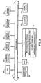
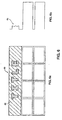
- Figure 1 is a view showing the outward appearance of representative computing equipment embodying a block selection-based table analysis system according to an embodiment of the present invention.
- FIG. 1 Shown in Figure 1 is computing equipment 1, such as an IBM PC or PC-compatible computer having a windowing operating system such as the Microsoft Windows95 operating system.
- Computing equipment 1 is provided with either a monochromatic or color display monitor 2, using which computing equipment 1 displays images to a user.
- Computing equipment 1 is also provided with fixed disk drive 3 for storing data files and application program files, keyboard 5 for inputting text data and for manipulating objects displayed on display screen 2, and pointing device 6, such as a mouse, which is provided for pointing to and manipulating objects displayed on display screen 2.
- pointing device 6 such as a mouse
- Computing system 1 also includes floppy disk drive 4 for reading from and writing to a floppy disk.
- Document image files including table images, as well as computer-executable process steps embodying the present invention may be stored either on fixed disk 3 or on a floppy disk inserted in floppy disk drive 4.
- document image files and/or computer-executable process steps may be obtained from a CD-ROM accessed via a CD-ROM drive (not shown).
- network interface 10 for interfacing with a local area network
- facsimile/modem interface 11 for sending and receiving facsimile messages and other data files.
- Document image files and computer-executable process steps embodying the present invention may be accessed over a network via network interface 10.
- facsimile/modem interface 11 can also be used for retrieving images and/or computer-executable process steps from the World Wide Web (hereafter WWW).
- the applications stored on fixed disk 3, including a block selection application are stored to disk 3 after being downloaded from a computer-readable medium, such as a floppy disk, a CD-ROM, a network drive, or the WWW.
- a computer-readable medium such as a floppy disk, a CD-ROM, a network drive, or the WWW.
- a document image may be input by scanner 7, which scans a document in order to provide bit-mapped image data of the document to computing equipment 1.
- the bit-mapped image data which includes bit-mapped table image data, may be stored onto fixed disk 3 in either a compressed or an uncompressed format.
- Printer 9 is provided for outputting document images processed by computing equipment 1.
- stored application programs such as a block selection application according to the present invention
- stored application programs are selectably activated to process and to manipulate stored data.
- commands are issued to display images on screen 2, and to print the displayed images using printer 9.
- FIG. 2 is a detailed block diagram showing the internal construction of computing equipment 1.
- computing equipment 1 includes a central processing unit (CPU) 20, such as a programmed microprocessor, interfaced to computer bus 21. Also interfaced to computer bus 21 are scanner interface 22, printer interface 23, network interface 24, fax/modem interface 26, display interface 27, keyboard interface 28, and mouse interface 29.
- CPU central processing unit
- printer interface 23 Also interfaced to computer bus 21 are scanner interface 22, printer interface 23, network interface 24, fax/modem interface 26, display interface 27, keyboard interface 28, and mouse interface 29.
- Main memory 30 such as random access memory (RAM), interfaces to computer bus 21 so as to provide CPU 20 with access to memory storage.
- RAM random access memory
- CPU 20 loads those steps from disk 3 or other storage media into main memory 30 and executes those process steps out of main memory 30.
- Read-only memory (ROM) 31 is used for storing computer-executable process steps, such as those used during boot-up, or basic input/output operating system (BIOS) sequences for operation of, for example, keyboard 5.
- BIOS basic input/output operating system
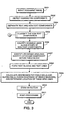
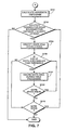
- Figure 3 is a flow diagram describing a method of block selection processing according to the present invention. The process steps shown in Figure 3 are preferably executed by CPU 20 in accordance with a block selection application stored on a computer-readable medium such as disk 3.
- the process steps of Figure 3 are used to input a document image, to detect connected components within the document image, to separate text and non-text connected components, to classify non-text connected components, to identify white areas along edges of non-text components, to form text block and text lines, to detect skew of the input image, and to post-process the image.
- Techniques for performing these general steps are disclosed in U.S. Patent Nos. 5,680,479 and 5,588,072.
- the process steps of Figure 3 are also used to identify reversed text areas within a table, which are text areas in which text is composed by white pixels surrounded by black pixels, to identify attached text connected components, to create and calculate addresses for table cells and super-cells, which are areas within a table region bounded by visible vertical and/or horizontal grid lines within the table and which contain at least one table cell, to check the existence of visible cell borders, and to determine the location of table grid lines according to the present invention.
- grid lines within a table are either visible or non-visible and also define each row and column identified within the table.
- bit-mapped pixel data of a document image is input into computing system 1 and is stored on disk 3.
- the pixel data is binary pixel data, that is, black and white image data.
- the image data is halftone image data, in which pixels are represented by one of several grayscale levels, or in a case where the pixel data is color image data, in which each pixel is represented by a multi-bit word encoding color data for the pixel, then threshold processing should be performed so as to binarize the non-binary pixel data into binary pixel data.
- image reduction may be performed following step S301. Such image reduction increases the speed of subsequent processing, but may also have an adverse effect on feature-intensive processing, such as optical character recognition.
- step S302 the input pixel data is analyzed so as to detect connected components within the document image.
- a connected component is a group of black pixels that is completely surrounded by white pixels.
- the detected connected components are rectangularized, or "blocked", by defining, for each connected component, a smallest rectangle circumscribing the connected component.
- step S304 the connected components are roughly classified into text connected components and non-text connected components. This classification is based on the size of the rectangles circumscribing the connected components and on the fact that non-text connected components are usually larger than text connected components. Detailed descriptions of steps S301, S302, and S304 are located within U.S. Patent Nos. 5,588,072 and 5,680,479.
- step S305 connected components classified as non-text in step S304 are further analyzed to determine whether they are lines, joint lines, pictures, line art, frames, tables, or unknown (i.e., none of the above).
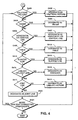
- Figure 4 is a flow diagram describing a method for analyzing non-text connected components according to step S305. Because individual steps of Figure 4 are described in greater detail in U.S. Patent Nos. 5,588,072 and 5,680,479, only a general description will be provided below.
- the non-text connected component classification described in Figure 4 is based on criteria thresholds which are formulated mathematically and calculated dynamically based on the size, width and the like of the connected components being analyzed.
- a non-text connected component is analyzed to determine whether it is a halftone (or continuous-tone) picture. If so, flow advances to step S402, at which point a "halftone (continuous-tone) picture" sub-attribute is assigned to the non-text connected component.
- step S404 it is determined whether the non-text connected component is a frame. If so, flow advances to step S405 at which time a "frame" sub-attribute is assigned to the connected component. If the determination in step S404 is negative, flow proceeds to step S406, wherein it is determined whether the non-text connected component is a horizontal or vertical line. Flow proceeds to step S407 in a case that the connected component is determined to be a horizontal or vertical line. In step S407, a "horizontal line” or “vertical line” sub-attribute is assigned to the non-text connected component.
- Step S409 is executed in a case that, in step S406, the non-text connected component is not determined to be a vertical line or a horizontal line.
- step S409 it is determined whether the non-text connected component is a table.
- internal white areas of the connected component are traced in four directions. Internal white areas are areas of white pixels completely surrounded by black pixels. If four internal white areas are found, and if the arrangement of the white areas is in a table-like grid such that the white areas are enclosed by horizontal and vertical lines, then the non-text connected component is designated as a table in step S410.
- a more detailed description for determining whether a connected component is a table is found in U.S. Patent No. 5,588,072, U.S. Patent No. 5,680,479, and U.S. Patent Application No. 08/514,252.
- step S410 the interior of the identified table is re-analyzed in accordance with steps S302 and S304 so as to identify and classify text and non-text connected components internal to the table.
- step S409 If it was not determined in step S409 that the non-text connected component is a table, flow advances to step S412 in which it is determined whether the non-text connected component is a slanted line. If so, a "slant line" sub-attribute is assigned to the non-text connected component in step S414.
- step S412 determines whether the non-text connected component is a line-art picture or a joint line. If the non-text connected component is not a line-art picture or a joint line, flow proceeds to step S416, wherein an "unknown" attribute is assigned to the connected component. If so, flow proceeds to step S417, wherein it is determined whether the non-text connected component is a joint line.
- step S419 the non-text connected component is, in step S419, designated as a line art picture. If the non-text connected component is determined to be a joint-line picture in step S417, flow proceeds to step S420, where a "joint line" sub-attribute is assigned to the component. Flow then proceeds to step S421.
- steps S402, S405, S407, S410, S414, S416, and S419 also flow to step S421, wherein it is determined whether additional non-text connected components remain to be classified. If so, flow returns to step S401. If not, flow proceeds to step S306 of Figure 3.
- step S306 invisible lines are identified along the edge of non-text connected components.
- invisible line identification is disclosed in detail in U.S. Patent Nos. 5,588,072 and 5,680,479.
- a vertical invisible line, or region of white pixels may be located in step S306 between two halftone picture connected components. This invisible line can be used in step S308 to determine whether text connected components located below the picture connected components should be grouped together or in separate columnar blocks.
- step S306 Flow proceeds from step S306 to step S307, in which reversed areas within table regions are identified.
- a reversed area is a region including text composed of white pixels surrounded by black pixels. Reversed areas within table regions are ignored in subsequent processing so as not to interfere with identification of other table features. A detailed description of reversed area identification is given below with respect to Figures 6 and 7.
- step S307 connected components which are attached to horizontal and vertical grid lines within table regions are identified. Identification and extraction of attached connected components are described generally below with respect to Figure 8 and in detail in commonly-assigned U.S. Patent Application No. 08/664,674. As also described below, identified attached components are used to identify other features within a table.
- step S308 in which text blocks are formed from the text connected components classified in step S304.
- close horizontal and vertical neighbours of each text connected component are aggregated into text blocks based on a statistical analysis of horizontal and vertical gaps between neighbouring text units.
- the formed text blocks are analyzed so as to form text lines. Step S308 is described in detail in U.S. Patent No. 5,588,072.
- step S309 process steps are executed in accordance with the present invention so as to analyze non-text connected components which have been designated as tables. More specifically, rows and columns within the tables are identified and row and column addresses are assigned to each table cell within the tables. Row and column address identification and assignment are described in detail below with respect to Figures 9 to 14.
- step S309 locations of vertical and horizontal table grid lines are calculated in step S309, the grid lines defining each identified row and column and being either visible and non-visible. A description of grid line calculation is given below with respect to Figures 15 and 16.
- Super-cells are also defined in step S309 based on table areas bounded by visible grid lines and containing at least one table cell. Row and column addresses are assigned to the super-cells, and visible grid line borders are identified surrounding each super-cell. Creation of super-cells and identification of visible borders are described with respect to Figures 17 and 18 hereinbelow.
- step S310 the skew of the input document image is detected and, if the skew angle exceeds a predefined maximum angle, an error code is output, signalling to the user that the document page is too skewed to complete the block selection process.
- Skew detection is disclosed in U.S. Patent Nos. 5,588,072 and 5,680,479.
- step S311 in which post-processing is performed.
- Post-processing is also disclosed in U.S. Patent Nos. 5,588,072 and 5,680,479.
- Post-processing is intended to result in a more compact and "clean" block representation of the document image, and can be tailored to suit particular types of subsequent processing, such as character recognition, data compression, and the like.
- post-processing involves associating text blocks with other text or non-text blocks.
- post-processing procedures depend on the page skew determined in step S310. For example, in a case that the page is only slightly skewed, gaps between text blocks are well-defined. Accordingly, blocks are combined aggressively. On the other hand, for a page having a larger skew, circumscribing rectangles likely overlap several text regions, therefore the rectangles are combined more conservatively. Block selection terminates after post-processing.
- Figure 3 process steps results in a detailed representation of the location and type of data within a document image.
- the Figure 3 process steps can be used in conjunction with an optical character recognition system so as to recognize characters represented by bit-mapped image data within a table, to convert the characters into an ASCII format, and to input the ASCII characters into a spreadsheet program based on determined row and column table addresses.
- the Figure 3 process determines information from which the internal features of a table, such as table grid lines, can be substantially reproduced.
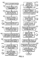
- FIG 5 is a flow diagram which describes in more detail the steps of the Figure 3 flow diagram, with particular attention paid to analysis of table features.
- steps S501 and S502 correspond to steps S301, S302, S304 and S305 of Figure 3.
- a document image is input in step S501 and connected components within the document image are detected and blocked in step S502.
- step S503 as described above with respect to steps S304 and S305, a table, as well as text blocks within the table, is identified.
- step S504 invisible lines along the edges of the table are also identified for use in subsequent text block formation.
- a reversed text area within a subject table is identified in step S505.
- a reversed area which is an area containing text composed of white pixels surrounded by black pixels, is an area to be ignored during subsequent table processing according to the present invention.
- Figure 6a shows reversed area 42 within table 40.
- the slanted lines within area 42 represent areas of black pixels, which are arranged so as to form the word "TITLE" within area 42.
- white areas represented by dashed lines, which are utilized during identification of table 40, as described with respect to step S409 above.
- step S701 in which is calculated a horizontal histogram representing total distances spanned by white boundary pairs within each row of pixels in a table.
- boundary pairs are coordinate locations determined by the intersection of a white area boundary (dashed lines in Figure 6a) with a particular row of pixels.
- Figure 6b shows histogram 44, which results from step S701 and corresponds to table 40.
- step S702 Beginning at the top of table 40, each row of pixels is analyzed in step S702, using the dimensions of table 40 and the data reflected in histogram 44, to determine whether the total distance between white boundary pairs within a row of pixels in a table is less than one-half of the total distance spanned by the row. If the foregoing condition is satisfied for N consecutively-analyzed rows, wherein N is a threshold value, flow proceeds to step S704.
- step S704 traced white areas are identified within the N rows identified in step S702. These areas correspond to the interior of each letter formed within area 42.
- step S706 the size of each identified white area is compared with a threshold size.
- the threshold size is preferably defined so as to differentiate text characters or small image noise from larger features. If a size of an identified white area is smaller than the threshold size, it is determined, in step S707, that the white area should be ignored during subsequent table processing. As a result, the white area is not considered during subsequent processing which utilizes white areas within a subject table. Flow then continues to step S709.
- step S706 If, in step S706, a size of an identified white area is not smaller than the threshold size, it is determined that the white area does not correspond to reversed text and flow proceeds to step S709.
- step S709 it is determined whether each white area identified in step S704 has been compared with the threshold size. If not, flow returns to step S706 and proceeds as described above. If so, flow proceeds to step S710.
- step S710 it is determined whether the last row of table 40 has been analyzed. If not, flow returns to step S702. However, if each row of table 40 has been analyzed, flow proceeds to step S506.
- step S506 connected components attached to grid lines within a table are identified and extracted.
- a system for performing such identification and extraction is described in U.S. Application No. 08/664,674, and therefore will only be described briefly below.
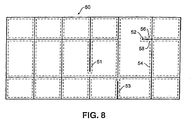
- Figure 8 shows table 50, surrounded on all sides by visible table grid lines.
- table area 50 lies other visible table grid lines, with each white area completely surrounded by black pixels being identified by dashed lines.
- several of the visible grid lines include gaps, often caused by poor printing, poor scanning, or the like. These gaps define partial grid lines 51, 52, and 53, also referred to as attached connected components.
- connected component 52 is extracted, that is, connected component 52 is identified as a connected component separate from the vertical and horizontal grid lines of table area 50.
- Connected components 51 and 53 are extracted in the same manner. Use of extracted attached connected components is described in detail below.
- step S507 text blocks and text lines are formed based on connected components located outside each table in the input document image.
- step S509 text blocks and text lines are formed based on text connected components located within each table.
- text blocks are examined to determine whether the text blocks are oriented vertically or horizontally, and text lines are formed based on the determination.
- only horizontal text lines are preferably formed in step S509.
- Each text block formed within a table is referred to hereinbelow as a table cell.
- text connected components which are not combined with other text connected components within a table block are also referred to herein as table cells.
- step S510 table columns are calculated and column addresses are assigned to table cells.
- Figures 9a and 9b are detailed flow diagrams for describing the process of step S510.
- the Figure 9a and 9b flow utilizes a vertical histogram of a table in order to identify table columns and, advantageously, ignores title areas, which may disrupt proper column identification.
- step S901 it is determined whether a subject table contains more than four text lines. If so, the top-most text line is assumed to be a title line and is ignored during column identification.
- step S901 table 60 is determined in step S901 to contain more than four rows of text lines. Accordingly, flow proceeds to step S902.
- step S902 a vertical histogram, such as vertical histogram 70 of Figure 10b, is calculated. As mentioned above, vertical histogram 70 is calculated ignoring top-most text line 61, which is assumed to be a title. If the determination in step S901 is negative, flow proceeds directly to step S904, in which a vertical histogram is calculated without ignoring any text lines in the subject table.
- the vertical histograms described in Figure 9a reflect, for each column of pixels in table 60, total vertical distances spanned by rectangles (not shown) circumscribing each connected component within table 60 and described with respect to steps S302 and S502.
- horizontal and vertical grid lines such as grid lines 64 and 66 are not blocked by circumscribing rectangles and therefore do not contribute to the data reflected in vertical histogram 70.
- connected components identified and extracted in step S506 are "blocked" and are therefore reflected in histograms calculated according to step S904 or step S902.
- attached connected component 68 is reflected by portion 71 of histogram 70.
- a distance over which a calculated histogram reflects a small amount of black pixels, P_gap, a portion of a histogram reflecting relatively more pixels and immediately following P_gap, W, and a histogram portion reflecting a small amount of pixels which immediately follows W, N_gap, are calculated beginning from the left-most point of histogram 70.
- P_gap, W, and N_gap initially correspond to areas 72, 74, and 75, respectively, of histogram 70. Columns are then assigned according to the respective locations and sizes of P_gap, W, and N_gap.
- steps S906 to S916 determine whether a table region corresponding to a current W should be included in a current column, whether a new column should be defined including the current W, or whether a new column should be defined ignoring the current W.
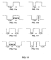
- step S906 it is determined in step S906 whether W is greater than a threshold value, which preferably reflects a small text character size. If so, flow proceeds to step S907, in which it is determined whether P_gap is narrow. If P_gap is not narrow, flow proceeds to step S917, in which a new column is defined including W. This configuration of W and P_gap is illustrated in Figure 11a.
- step S907 If it is determined in step S907 that P_gap is narrow, flow proceeds to step S909, wherein the definition of the current column is extended to include W. This situation is shown in Figure 11b. Flow then returns to step S905.
- step S906 If, in step S906, it is determined that W is not greater than the threshold value, flow proceeds to step S910, in which it is determined whether P_gap is wide. If so, flow proceeds to step S911, where it is determined whether W reflects a cut connected component, such as connected component 52 of table 50. If W does not reflect a cut connected component, flow proceeds to step S917 wherein a new column is defined, which includes W. Figure 11c reflects this situation.
- step S911 If, in step S911, it is determined that W reflects a cut connected component, as shown in Figure 11d, the right-most border of the current column is defined at the left edge of P_gap, and flow returns to step S905 to define a new P-gap, W, and N_gap. Accordingly, the reflected cut connected component is not included in any defined column.
- step S912 it is determined whether N_gap is wide. If not, flow proceeds to step S914 wherein it is determined whether the current column is the first column in the subject table. If so, flow proceeds to step S917 as described above. Such a situation is reflected in Figure 11e, wherein the current column is defined to terminate at the initial point of N_gap.
- step S914 If, in step S914, it is determined that the current column is not the first column in the subject table, flow proceeds to step S915, wherein the current column is extended to include W. Such a situation is shown in Figure 11f. Flow then returns to step S905.
- step S916 determines whether W reflects a cut connected component. If not, flow proceeds to step S915 in order to include W, shown in Figure 11g, into the current column. If the determination in step S916 is affirmative, the right-most border of the current column is defined at the left edge of P-gap, and flow simply returns to step S905 so as to ignore the cut connected component. This situation is shown in Figure 11h.
- step S917 If the right-most portion of a histogram reflecting the subject table has been reached at this point, flow continues to step S920. If not, flow returns to step S905.
- Step S920 Upon reaching step S920, several columns are defined within a subject table. These columns are addressed sequentially from left to right and are defined according to left and right X-coordinate boundaries.
- Figures 12a and 12b show table 76 and corresponding column definitions A and B. As shown in Figure 12b and due to table cell 79, column A should be split into two separate columns. Steps S920 and S921 are meant to address this situation.
- step S920 left and right boundaries of detected white areas and cut vertical grid lines are examined to determine whether these features lie close to any defined column boundaries. If so, flow continues to step S922. If any detected white boundaries or cut grid lines are not close to a column boundary, flow proceeds to step S921, in which a new column is defined surrounding the white boundaries or cut grid lines. All column addresses are then updated accordingly.
- Figure 12c shows the column definitions of table 76 after step S921.
- a new column B is defined adjacent to the right boundary of area 78. Accordingly, the address of the previous column B is updated to column C.
- each table cell is assigned a column address corresponding to the column locations spanned by the table cell.
- the assigned column address may include a range of column addresses. For example, table cell 77 is assigned column address A, while table cell 79 is assigned column address A to B. Flow proceeds from Step S922 to step S511 in order to calculate table rows and assign row addresses to table cells.
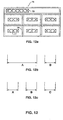
- FIG 13 is a detailed flow diagram describing the process steps executed in step S511 to calculate table rows and assign row addresses to table cells.
- Flow begins in step S1301, in which a horizontal histogram of a subject table is created.
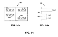
- Figure 14 illustrates subject table 80 and horizontal histogram 86 created in accordance with step S1301.
- Horizontal histogram 86 reflects, for each row of pixels in table 80, horizontal distances spanned by rectangles (not shown) circumscribing each connected component within table 80.
- peak width pw1 of histogram 86 reflects table cells 81 and 82
- peak width pw2 reflects table cell 84
- peak width pw3 reflects table cell 83.
- Valley widths vw1 and vw2 indicate regions between peak width pw1 and peak width pw2, and between peak width pw2 and peak width pw3, respectively.
- step S1302 the upper-most peak in histogram 86 is initially examined. Particularly, it is determined whether an initial peak width pw in a current row is greater than a threshold value, the threshold value preferably being indicative of a minimum character size, and whether a next valley width vw is greater than a second threshold value, the second threshold value preferably being indicative of a minimum row spacing. If both conditions are satisfied, flow proceeds to step S1304, wherein a new row is defined corresponding to a next-encountered peak. If one of the conditions is not satisfied in step S1302, flow proceeds to step S1305, in which the current row is extended so as to include a next-encountered peak. In either case, flow proceeds from step S1304 and step S1305 to step S1306.
- step S1306 it is determined whether additional horizontal histogram peaks exist. If so, flow returns to step S1302. If not, flow proceeds to step S1307.
- step S1307 horizontal white area boundaries and attached horizontal grid lines within table 80 are identified. Similarly to above-described steps S920 to S922, in a case that an identified white boundary or grid line is not close to any row boundaries, a new row is defined and row addresses are updated accordingly. Flow then proceeds to step S512.
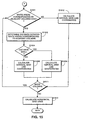
- step S512 vertical and horizontal grid line locations are calculated.
- Figure 15 is a flow diagram describing the process steps of step S512 in detail.
- Flow begins at step S1501, wherein it is determined whether a current and an adjacent column are each surrounded by corresponding traced white areas. If so, flow proceeds to step S1502.
- step S1502 a distance between the corresponding white areas is determined.
- step S1504 if the distance determined in step S1502 is not smaller than a threshold distance, flow proceeds to step S1505, wherein a vertical grid line coordinate is calculated. If it is determined in step S1504 that the distance is smaller than a threshold value, flow proceeds to step S1506, wherein a vertical grid line coordinate is calculated based on, preferably, a different equation than that used in step S1505.
- step S1501 If it is determined in step S1501 that white areas corresponding to adjacent columns do not exist, flow proceeds to step S1510 in which a vertical grid line coordinate is calculated using an equation different than those used in step S1505 and step S1506. Flow then proceeds to step S1511, at which it is determined whether more columns exist. If so, flow returns to step S1501. If not, flow proceeds to step S1512.
- step S1512 horizontal grid lines for a subject table are calculated using steps substantially similar to those described in steps S1501 to S1511, although rotated through 90 degrees.
- Figure 16 illustrates two subject tables for describing the Figure 15 flow.
- table 90 contains column C1 and column C2, column C1 being bounded by X-coordinates C1L and C1R and with column C2 being bounded by X-coordinates C2L and C2R.
- Traced white area 91 corresponds to column C1 and contains border b1
- traced white area 92 corresponds to column C2 and contains border b2.
- step S1501 it is determined that white areas corresponding to each of adjacent columns C1 and C2 exist.
- step S1502 the distance between b1 and b2 is determined.
- areas 91 and 92 contain regions sharing a common X-coordinate, for example, in a case that a slanted vertical line separates areas 91 and 92, border b1 is defined as the right-most X-coordinate of area 91, and b2 is defined as the left-most X-coordinate of area 92.
- step S1504 If the distance between b1 and b2 is judged to be small in step S1504, flow proceeds to step S1506, wherein a vertical grid line coordinate is calculated to exist at min[max((b1 + b2)/2, C1R, C2L)].
- step S512 After executing step S1512 with respect to horizontal grid lines, flow proceeds to step S514, in which super-cells are identified.
- Figure 17 is a detailed flow diagram for describing super-cell identification in accordance with step S514.
- step S1701 super-cells are identified corresponding to each white area bordered by black pixels within a subject table.
- an "artificial" super-cell is also formed in step S1701 having the same location and dimensions of the table cell.
- step S1702 each artificial super-cell is reformatted to approximate dimensions of surrounding visible or non-visible table grid lines. Flow then continues to step S1704.
- step S1704 the top, bottom, left, and right borders of each super-cell are examined to identify whether or not visible grid lines are adjacent to the borders.
- step S1705 row and column addresses are assigned to the super-cells based on the rows and columns calculated in steps S510 and S511. Flow continues from step S1705 to step S515.
- Figure 18 shows a subject table for describing the Figure 17 flow diagram.
- table 100 contains table cells 101, 102, 104 and 105.
- Table cell 101 is not surrounded by a white area because table cell 101 does not lie in an area completely surrounded by black pixels.
- table cells 102, 104 and 105 are surrounded by white areas 106, 107 and 109.
- super-cells are initially defined in step S1701 corresponding to each white area within table 100. Accordingly, super-cells are defined corresponding to white areas 106, 107 and 109. These super-cells are shown in Figure 18b as super-cells 115, 111 and 112. As described above, because no white area surrounds table cell 101, an artificial super-cell is also defined having identical coordinates to those of table cell 101.
- step S1702 the artificial super-cell is reformatted according to the following algorithm to approximate visible or non-visible table grid lines surrounding the artificial super-cell:
- each super-cell is examined to identify visible grid lines bordering the super-cell. For example, visible grid lines are identified at the right and bottom of super-cell 114, at the top, right, left and bottom of super-cell 115, at the top, right, left and bottom of super-cell 112, and at the top, right, left and bottom of super-cell 111.
- step S1704 it is determined in step S1704 whether the partial grid line exceeds a certain threshold length corresponding to the length of a "complete" border. If so, it will be determined in step S1704 that the partial grid line completely borders the particular side of the particular super-cell.
- step S1705 row and column addresses are assigned to each super-cell of Figure 18b.
- the super-cells share the same column and row locations as their respective table cells. Accordingly, super-cells 111, 112, 114 and 115 also share the row and column addresses of table cells 104, 105, 101 and 102, respectively. It should be noted that, in a case that a super-cell is located within several rows or columns, the super-cell address will contain a row and/or column address range, such as (1, 2-4). Flow then proceeds to step S515.
- step S515 table cells having a row and/or column address range are split, if appropriate.
- the foregoing process steps may result in table cells spanning several rows or columns which should be more properly classified as multiple table cells.
- Figure 19, comprising Figures 19a, 19b, and 19c, illustrates several table cells having a column address range.
- Figure 20 illustrates a table cell having a row address range.
- Figure 21a and Figure 21b describe steps for splitting table cells having a column address range and a row address range, respectively.
- step S2101 a table cell having a column address range is identified.
- step S2102 a vertical histogram of the identified table cell is calculated. The vertical histogram reflects, for each column of pixels in the identified table cell, the total vertical distance spanned by rectangles (not shown) circumscribing each connected component in the table cell.
- step S2104 it is determined whether an area of the histogram corresponding to a space between adjacent columns of the table cell reflects any black pixels. If any black pixels are reflected, flow continues to step S2105.
- step S2105 it is determined whether the histogram of the area between the columns is non-zero for a continuous distance greater than a threshold distance. If so, flow proceeds to step S2114, in which it is determined whether additional columns exist within the address range of the subject table cell. Such a situation is illustrated in Figure 19a, in which 1 indicates a continuous non-zero portion of a histogram between columns r and r+1. If additional columns exist, flow returns to step S2104.
- step S2115 it is determined in step S2115 whether the subject table contains additional table cells having a column address range. If so, flow returns to step S2102. If not, flow continues to step S2116 of Figure 21b.
- Figure 19b illustrates a situation in which, in step S2105 of Figure 21a, it is determined that continuous non-zero portion m is less than a threshold. Accordingly, flow proceeds to step S2106, in which it is determined whether a separate non-zero portion is located between columns s and s+1 of Figure 19b. If not, table cell 116 is redefined as two new table cells, one having column address s and the other having column address s+1, such that neither of the two new cells contain portion m.
- step S2106 If a separate non-zero portion is located between columns s and s+1 in step S2106, flow continues to step S2114 and continues as described above.
- step S2104 it is determined that the area between two columns of a subject table cell does not contain black pixels, flow proceeds to step S2110.
- step S2110 the area between the two columns is extended into the two columns until a black pixel is encountered in each column.
- area n between columns t and t+1 of table cell 117 contains no black pixels. Accordingly, in step S2110, area n is extended in both horizontal directions until black pixels within table cell 117 are encountered. The resulting area is indicated as n'.
- step S2111 it is determined whether the length of an area such as area n' is greater than a threshold value. If so, table cell 117 is split into two table cells in step S2112 and flow continues to step S2114. If not, flow simply proceeds to step S2114 and eventually to step S2116 of Figure 21b.
- step S2116 a subject table cell having a row address range is retrieved.
- step S2117 two rows in the row address range are examined to determine a distance between the rows and a mid-point between the rows. These two quantities are represented by row_dist and mid_row in Figure 20.
- a table cell includes row R1 and row R2 in its row address range.
- the upper bound of row R1 is defined by coordinate R1U and the lower bound of row R1 is define by coordinate R1L.
- the upper bound of row R2 is defined by R2U and the lower bound is defined by R2L.
- the quantity mid-_row refers to the mid-point between R1L and R2U.
- the quantity row_dist refers to the distance between R1L and R2U.
- step S2119 it is determined whether the retrieved table cell includes consecutive text lines located on opposite sides of mid_row and whether row_dist is greater than a threshold line size. If so, flow proceeds to step S2120, wherein the subject table cell is cut into two cells at the mid_row coordinate, one of the two cells containing row R1 in its row address and the other cell containing row R2 in its row address. Flow then proceeds to step S2121.
- step S2119 determines whether the subject table cell contains additional rows. If so, flow returns to step S2117. If not, flow continues to step S2122, in which it is determined whether other table cells having a row address range exist in the subject table. If so, flow returns to step S2116. If not, flow continues to step S516 in order to delete spurious rows and columns resulting from the flow of steps S510 to S515.
- Figure 22 is a diagram for describing the process steps of step S516.
- numeral 130 indicates a right border of column C5.
- Right border 130 is located adjacent to vertical grid line 132. Since no connected components exist in column C6, located between right column border 130 and vertical grid line 132, column C6 is deleted by eliminating border 130. Accordingly, grid line 132 will be newly defined as the right-most border of column C5.
- Figure 22b illustrates a second situation for which column locations are updated in step S516.
- slanted line 134 has caused column C9 to be defined between left border 135 and right border 136. Accordingly, column C9 is deleted by replacing borders 135 and 136 by a single border (not shown) between newly-expanded columns C8 and C10. Flow continues from step S516 to step S517.
- step 517 row and column addresses of super-cells are adjusted so as to reduce incorrect address assignment due to slanted table grid lines.
- Figure 23 illustrates a situation in which a slanted table grid line has caused incorrect row and column address assignment.
- slanted vertical grid line 140 intersects columns u and u+1, which are defined at their right and left borders, respectively, by non-visible grid line 141. Due to slanted line 140, super-cells 143 to 145 have a column address range of (u - u+1), even though the black pixels contained within cells 143 to 145 exist completely within column u+1.
- step S517 Several criteria are evaluated in step S517 to determine whether a column address of a super-cell should be updated to exclude a left-most column. First, it is determined whether a left border of a subject super-cell lying in column u+1 is located in column u. Second, it is determined whether a distance between the left border and grid line 141 is less than a threshold value. Third, it is determined whether all connected components within the super-cell are to the right of grid line 141. Fourth, it is determined whether a super-cell exists within column u at the row addresses of the subject super-cell. If these four criteria are satisfied, column u is deleted from the definition of the subject super-cell and the subject super-cell dimensions are redefined.
- the modified criteria it is first determined whether a right border of a subject super-cell lying in column u is located in column u+1. Second, it is determined whether a distance between the right border and grid line 141 is less than a threshold value. Third, it is determined whether all connected components within the super-cell are to the left of grid line 141. Fourth, it is determined whether a super-cell exists within column u+1 at the row addresses of the subject super-cell. If these four criteria are satisfied, column u+1 is deleted from the definition of the subject super-cell and the subject super-cell dimensions are redefined.
- Step S519 is executed after step S517 so as to create dummy super-cells or to extend a super-cells in case a "super-cell hole” exists.
- Figure 26 is an example showing situations in which "super-cell holes" arise. As shown in Figure 26a, no visible grid line exists to the left of table cell 160. Therefore, as described above with respect to the method of Figure 17, super-cell is created, and is bordered by non-visible grid lines to its left and bottom. White area 163 is surrounded by black pixels, therefore super-cell 164 was assigned in step S1701 corresponding to white area 163. In contrast, since area 165 neither contains a connected component nor a white area surrounded completely by black pixels, a super-cell has not been assigned to area 165.
- step S2501 each super-cell border is extended to a corresponding visible grid line.
- Super-cell size and border information is then updated in step S2504.
- step S2505 the left, right top and bottom edges of a subject table are analyzed to determine whether any areas such as area 165 exist. If so, a dummy super-cell is created surrounding each of such areas in step S2506. Flow then proceeds to step S520. If no areas such as area 165 exist, flow proceeds directly from step S2505 to step S520.
- super-cell 162 is extended as shown in Figure 26b. Also shown in Figure 26b is dummy super-cell 167 corresponding to area 165.
- step S520 includes steps to create a dummy cell in a case that a "cell hole" exists.
- Figure 27 shows a table containing a cell hole.
- table 170 contains, among other things, super-cell 172.
- table cells 174, 175 and 176 are table cells 174, 175 and 176. Based on the row and column addresses of table cells 174 to 176 and on the dimensions of super-cell 172, it is determined that a table cell is missing from location 177, indicated by a dash line. This location is referred to as a cell hole. Accordingly, in step S520, a cell is defined at location 177.
- the cell defined in step S520 does not contain any connected components. However, such a cell is useful for defining and quickly reproducing table features. Moreover, such a cell allows data to be easily added at location 177 to a file representing table 170 because the file will contain a pre-defined cell at location 177.
- Figure 28 is an example of a table having visible table cell borders according to step S521. Particularly, Figure 28a shows table 180 containing table cells 181 to 186. Also shown are super-cell 187, which contains table cells 181 and 182, and super-cell 188, which contains table cells 183 to 186.
- each table cell is examined to determine whether it is bounded by a visible grid line on its top, bottom, left, or right.
- table cell 181 is bounded on its top and right sides
- table cell 182 is bounded on its right and bottom sides
- table cell 183 is bounded on its top and left sides
- table cell 184 is bounded on its left and bottom sides
- table cell 185 is bounded on its bottom and right sides
- table cell 186 is bounded on its top and right sides.
- the determined information can be stored along with definitions of table cell type, table cell row and column address, and table cell location and size.
- Figure 28b is an example for describing storing data regarding visible borders surrounding table cells.
- Figure 28b shows a matrix representing each table cell of table 180.
- the circles in Figure 28b indicate non-visible table cell borders, while the dashes indicate visible table cell borders.
- internal grid lines of a table analyzed according to the present invention can be quickly reproduced.
- step S521 Flow continues from step S521 to S522, wherein skew detection and post-processing is performed as described above with respect to steps S310 and S311 of Figure 3.
- the information determined by the Figure 5 flow is preferably stored in a hierarchical tree structure representing a subject table.
- data regarding super-cells which includes row and column addresses of a super-cell, super-cell coordinates, table cells included within a super-cell, and information regarding the existence of visible borders of the super-cell, are stored in a node representing the table block, such as node 200 in Figure 29a.
- Node 200 also stores table coordinates, column and row range, and location of visible and invisible vertical and horizontal grid lines.
- Descending from node 200 are table cell nodes 202 to 204. These table cell nodes contain data representative of table cell coordinates, table cell row and column addresses, the existence of visible table cell borders, and surrounding super-cells are stored in nodes representative of a subject table cell.
- Figure 29b shows an alternative representation of the Figure 29a hierarchical tree.
- super-cell nodes 205 and 206 are defined separately from table node 200, and have descending therefrom nodes representative of table cells contained within a corresponding super-cell. It should be understood that in the Figure 29b tree structure, super-cell nodes 205 and 206, rather than node 200, contain data regarding the super-cell frames, which includes column and row addresses of a super-cell, super-cell coordinates, table cells included within a super-cell, and information regarding the existence of visible borders of the super-cell.
Landscapes
- Engineering & Computer Science (AREA)
- Computer Vision & Pattern Recognition (AREA)
- Physics & Mathematics (AREA)
- Artificial Intelligence (AREA)
- General Physics & Mathematics (AREA)
- Multimedia (AREA)
- Theoretical Computer Science (AREA)
- Computer Graphics (AREA)
- Geometry (AREA)
- Character Input (AREA)
- Image Analysis (AREA)
Applications Claiming Priority (2)
| Application Number | Priority Date | Filing Date | Title |
|---|---|---|---|
| US09/002,684 US6173073B1 (en) | 1998-01-05 | 1998-01-05 | System for analyzing table images |
| US2684 | 1998-01-05 |
Publications (3)
| Publication Number | Publication Date |
|---|---|
| EP0927950A2 EP0927950A2 (en) | 1999-07-07 |
| EP0927950A3 EP0927950A3 (en) | 2001-10-17 |
| EP0927950B1 true EP0927950B1 (en) | 2004-08-25 |
Family
ID=21701969
Family Applications (1)
| Application Number | Title | Priority Date | Filing Date |
|---|---|---|---|
| EP98310566A Expired - Lifetime EP0927950B1 (en) | 1998-01-05 | 1998-12-22 | System for analysing table images |
Country Status (5)
| Country | Link |
|---|---|
| US (1) | US6173073B1 (https=) |
| EP (1) | EP0927950B1 (https=) |
| JP (1) | JP4251586B2 (https=) |
| CN (1) | CN1143239C (https=) |
| DE (1) | DE69825856D1 (https=) |
Families Citing this family (51)
| Publication number | Priority date | Publication date | Assignee | Title |
|---|---|---|---|---|
| US7099507B2 (en) * | 1998-11-05 | 2006-08-29 | Ricoh Company, Ltd | Method and system for extracting title from document image |
| JP2000339301A (ja) * | 1999-03-23 | 2000-12-08 | Canon Inc | 文書分割装置及び方法、及びそのプログラムを記憶した記憶媒体 |
| US6757870B1 (en) * | 2000-03-22 | 2004-06-29 | Hewlett-Packard Development Company, L.P. | Automatic table detection method and system |
| JP2002032770A (ja) * | 2000-06-23 | 2002-01-31 | Internatl Business Mach Corp <Ibm> | 文書処理方法、文書処理システムおよび媒体 |
| US6778700B2 (en) * | 2001-03-14 | 2004-08-17 | Electronics For Imaging, Inc. | Method and apparatus for text detection |
| CA2391692C (en) * | 2002-07-15 | 2006-07-04 | Allan Williams | Computer database with adaptive storage space architecture |
| US20040066538A1 (en) * | 2002-10-04 | 2004-04-08 | Rozzi William A. | Conversion of halftone bitmaps to continuous tone representations |
| US7308159B2 (en) * | 2004-01-16 | 2007-12-11 | Enuclia Semiconductor, Inc. | Image processing system and method with dynamically controlled pixel processing |
| US8095871B2 (en) * | 2004-05-06 | 2012-01-10 | Siemens Corporation | System and method for GUI supported specifications for automating form field extraction with database mapping |
| US7668404B2 (en) * | 2004-06-30 | 2010-02-23 | Lexmark International, Inc. | Method and system of deskewing an image using monochrome conversion to separate foreground from background |
| US7707488B2 (en) * | 2006-02-09 | 2010-04-27 | Microsoft Corporation | Analyzing lines to detect tables in documents |
| JP4135752B2 (ja) * | 2006-06-12 | 2008-08-20 | コニカミノルタビジネステクノロジーズ株式会社 | 画像処理装置、画像処理方法及び画像処理プログラム |
| JP4665933B2 (ja) * | 2006-07-04 | 2011-04-06 | セイコーエプソン株式会社 | 文書編集支援装置、プログラムおよび記憶媒体 |
| US7801358B2 (en) * | 2006-11-03 | 2010-09-21 | Google Inc. | Methods and systems for analyzing data in media material having layout |
| WO2009001462A1 (ja) * | 2007-06-28 | 2008-12-31 | Fujitsu Limited | スプレッドシート生成プログラム、該プログラムを記録した記録媒体、スプレッドシート生成装置、およびスプレッドシート生成方法 |
| US8155442B2 (en) * | 2008-02-04 | 2012-04-10 | The Neat Company, Inc. | Method and apparatus for modifying the histogram of an image |
| CN101551859B (zh) * | 2008-03-31 | 2012-01-04 | 夏普株式会社 | 图像辨别装置及图像检索装置 |
| US8144986B2 (en) * | 2008-09-05 | 2012-03-27 | The Neat Company, Inc. | Method and apparatus for binarization threshold calculation |
| US8443278B2 (en) | 2009-01-02 | 2013-05-14 | Apple Inc. | Identification of tables in an unstructured document |
| US8214733B2 (en) * | 2010-04-28 | 2012-07-03 | Lexmark International, Inc. | Automatic forms processing systems and methods |
| US8261180B2 (en) * | 2009-04-28 | 2012-09-04 | Lexmark International, Inc. | Automatic forms processing systems and methods |
| JP2013500527A (ja) * | 2009-07-30 | 2013-01-07 | オセ−テクノロジーズ・ベー・ヴエー | 文書内の表の自動的な位置特定 |
| US20110032266A1 (en) * | 2009-08-07 | 2011-02-10 | Delphi Technologies, Inc. | Glare detection and mitigation method for a photo-sensitive display device |
| CN101866335B (zh) * | 2010-06-14 | 2012-12-12 | 深圳市万兴软件有限公司 | 一种文档转换中的表格处理方法及装置 |
| CN101984426B (zh) * | 2010-10-21 | 2013-04-10 | 优视科技有限公司 | 用于对网页图片进行字符切分的方法及装置 |
| US8549399B2 (en) | 2011-01-18 | 2013-10-01 | Apple Inc. | Identifying a selection of content in a structured document |
| US8380753B2 (en) | 2011-01-18 | 2013-02-19 | Apple Inc. | Reconstruction of lists in a document |
| US8731296B2 (en) * | 2011-04-21 | 2014-05-20 | Seiko Epson Corporation | Contact text detection in scanned images |
| EP2807608B1 (en) | 2012-01-23 | 2024-04-10 | Microsoft Technology Licensing, LLC | Borderless table detection engine |
| CN104067293B (zh) | 2012-01-23 | 2017-07-25 | 微软技术许可有限责任公司 | 矢量图分类引擎 |
| CN103377177B (zh) * | 2012-04-27 | 2016-03-30 | 北大方正集团有限公司 | 一种数字版式文件中识别表格的方法及装置 |
| US9953008B2 (en) | 2013-01-18 | 2018-04-24 | Microsoft Technology Licensing, Llc | Grouping fixed format document elements to preserve graphical data semantics after reflow by manipulating a bounding box vertically and horizontally |
| US9047528B1 (en) * | 2013-02-19 | 2015-06-02 | Amazon Technologies, Inc. | Identifying characters in grid-based text |
| US10076751B2 (en) | 2013-12-30 | 2018-09-18 | General Electric Company | Systems and methods for reagent storage |
| US9399216B2 (en) | 2013-12-30 | 2016-07-26 | General Electric Company | Fluid transport in microfluidic applications with sensors for detecting fluid presence and pressure |
| JP6435636B2 (ja) * | 2014-05-15 | 2018-12-12 | 富士ゼロックス株式会社 | 情報処理装置及び情報処理プログラム |
| CN104050487B (zh) * | 2014-06-06 | 2017-06-16 | 华东师范大学 | 一种基于布局信息分析的邮件图像方向辨别方法 |
| US9235757B1 (en) * | 2014-07-24 | 2016-01-12 | Amazon Technologies, Inc. | Fast text detection |
| CN105426834B (zh) * | 2015-11-17 | 2019-02-22 | 中国传媒大学 | 一种基于投影特征与结构特征进行表格图像检测的方法 |
| CN106446881B (zh) * | 2016-07-29 | 2019-05-21 | 北京交通大学 | 从医疗化验单图像中提取化验结果信息的方法 |
| CN106156761B (zh) * | 2016-08-10 | 2020-01-10 | 北京交通大学 | 面向移动终端拍摄的图像表格检测与识别方法 |
| US10242257B2 (en) * | 2017-05-18 | 2019-03-26 | Wipro Limited | Methods and devices for extracting text from documents |
| US10410386B2 (en) * | 2017-09-15 | 2019-09-10 | Konica Minolta Laboratory U.S.A., Inc. | Table cell validation |
| US11650970B2 (en) | 2018-03-09 | 2023-05-16 | International Business Machines Corporation | Extracting structure and semantics from tabular data |
| CN108470021B (zh) * | 2018-03-26 | 2022-06-03 | 阿博茨德(北京)科技有限公司 | Pdf文档中表格的定位方法及装置 |
| US11200413B2 (en) | 2018-07-31 | 2021-12-14 | International Business Machines Corporation | Table recognition in portable document format documents |
| WO2020225430A2 (en) * | 2019-05-08 | 2020-11-12 | Vrije Universiteit Brussel | Computer implemented method for segmenting a binarized document |
| US11062133B2 (en) * | 2019-06-24 | 2021-07-13 | International Business Machines Corporation | Data structure generation for tabular information in scanned images |
| CN114357958A (zh) * | 2020-09-30 | 2022-04-15 | 中移(苏州)软件技术有限公司 | 一种表格提取方法、装置、设备及存储介质 |
| US12260662B2 (en) * | 2021-04-15 | 2025-03-25 | Microsoft Technology Licensing, Llc | Inferring structure information from table images |
| US11829701B1 (en) * | 2022-06-30 | 2023-11-28 | Accenture Global Solutions Limited | Heuristics-based processing of electronic document contents |
Family Cites Families (17)
| Publication number | Priority date | Publication date | Assignee | Title |
|---|---|---|---|---|
| US5185813A (en) | 1988-01-19 | 1993-02-09 | Kabushiki Kaisha Toshiba | Document image processing apparatus |
| US5131053A (en) | 1988-08-10 | 1992-07-14 | Caere Corporation | Optical character recognition method and apparatus |
| US5101448A (en) | 1988-08-24 | 1992-03-31 | Hitachi, Ltd. | Method and apparatus for processing a document by utilizing an image |
| US5129012A (en) | 1989-03-25 | 1992-07-07 | Sony Corporation | Detecting line segments and predetermined patterns in an optically scanned document |
| JP2812982B2 (ja) * | 1989-04-05 | 1998-10-22 | 株式会社リコー | 表認識方法 |
| JP2940936B2 (ja) | 1989-06-06 | 1999-08-25 | 株式会社リコー | 表領域識別方法 |
| US5448692A (en) * | 1991-03-27 | 1995-09-05 | Ricoh Company, Ltd. | Digital image processing device involving processing of areas of image, based on respective contour line traces |
| JPH05250357A (ja) | 1992-03-05 | 1993-09-28 | Ricoh Co Ltd | 画像読取修正装置および修正画像形成装置 |
| US5335290A (en) | 1992-04-06 | 1994-08-02 | Ricoh Corporation | Segmentation of text, picture and lines of a document image |
| US5680479A (en) | 1992-04-24 | 1997-10-21 | Canon Kabushiki Kaisha | Method and apparatus for character recognition |
| US5594815A (en) * | 1992-10-19 | 1997-01-14 | Fast; Bruce B. | OCR image preprocessing method for image enhancement of scanned documents |
| JP2789971B2 (ja) * | 1992-10-27 | 1998-08-27 | 富士ゼロックス株式会社 | 表認識装置 |
| US5485566A (en) | 1993-10-29 | 1996-01-16 | Xerox Corporation | Method of finding columns in tabular documents |
| US5588072A (en) | 1993-12-22 | 1996-12-24 | Canon Kabushiki Kaisha | Method and apparatus for selecting blocks of image data from image data having both horizontally- and vertically-oriented blocks |
| US5689342A (en) | 1994-11-17 | 1997-11-18 | Canon Kabushiki Kaisha | Image processing method and apparatus which orders text areas which have been extracted from an image |
| US5661818A (en) | 1995-01-27 | 1997-08-26 | Eastman Kodak Company | Method and system for detecting grids in a digital image |
| US5848186A (en) * | 1995-08-11 | 1998-12-08 | Canon Kabushiki Kaisha | Feature extraction system for identifying text within a table image |
-
1998
- 1998-01-05 US US09/002,684 patent/US6173073B1/en not_active Expired - Lifetime
- 1998-12-22 EP EP98310566A patent/EP0927950B1/en not_active Expired - Lifetime
- 1998-12-22 DE DE69825856T patent/DE69825856D1/de not_active Expired - Lifetime
-
1999
- 1999-01-04 JP JP00023999A patent/JP4251586B2/ja not_active Expired - Fee Related
- 1999-01-05 CN CNB991010043A patent/CN1143239C/zh not_active Expired - Fee Related
Also Published As
| Publication number | Publication date |
|---|---|
| EP0927950A3 (en) | 2001-10-17 |
| JPH11259655A (ja) | 1999-09-24 |
| JP4251586B2 (ja) | 2009-04-08 |
| CN1143239C (zh) | 2004-03-24 |
| CN1237745A (zh) | 1999-12-08 |
| US6173073B1 (en) | 2001-01-09 |
| DE69825856D1 (de) | 2004-09-30 |
| EP0927950A2 (en) | 1999-07-07 |
Similar Documents
| Publication | Publication Date | Title |
|---|---|---|
| EP0927950B1 (en) | System for analysing table images | |
| US5465304A (en) | Segmentation of text, picture and lines of a document image | |
| US6009196A (en) | Method for classifying non-running text in an image | |
| US6512848B2 (en) | Page analysis system | |
| US6903751B2 (en) | System and method for editing electronic images | |
| US5452374A (en) | Skew detection and correction of a document image representation | |
| US5889886A (en) | Method and apparatus for detecting running text in an image | |
| EP0758775B1 (en) | Feature extraction system | |
| US8000529B2 (en) | System and method for creating an editable template from a document image | |
| JP3359095B2 (ja) | 画像処理方法及び装置 | |
| US6711292B2 (en) | Block selection of table features | |
| JP4655335B2 (ja) | 画像認識装置、画像認識方法および画像認識プログラムを記録したコンピュータ読取可能な記録媒体 | |
| JPH08235349A (ja) | ページ解析システム | |
| US9189459B2 (en) | Document image layout apparatus | |
| JP4077904B2 (ja) | 情報処理装置およびその方法 | |
| JP2008176521A (ja) | パターン分離抽出プログラム、パターン分離抽出装置及びパターン分離抽出方法 | |
| US6360006B1 (en) | Color block selection | |
| JP5412903B2 (ja) | 文書画像処理装置、文書画像処理方法および文書画像処理プログラム | |
| US7783108B2 (en) | Document management method and apparatus | |
| JP3728209B2 (ja) | 画像処理方法及び装置及びコンピュータプログラム及び記憶媒体 | |
| JP2008129793A (ja) | 文書処理システムおよび装置および方法、およびプログラムを記録した記録媒体 | |
| JP2019195117A (ja) | 情報処理装置、情報処理方法、及びプログラム | |
| JP4587167B2 (ja) | 画像処理装置及び画像処理方法 | |
| JP3406942B2 (ja) | 画像処理装置及び方法 | |
| Chao | Graphics extraction in a PDF document |
Legal Events
| Date | Code | Title | Description |
|---|---|---|---|
| PUAI | Public reference made under article 153(3) epc to a published international application that has entered the european phase |
Free format text: ORIGINAL CODE: 0009012 |
|
| AK | Designated contracting states |
Kind code of ref document: A2 Designated state(s): AT BE CH CY DE DK ES FI FR GB GR IE IT LI LU MC NL PT SE Kind code of ref document: A2 Designated state(s): DE FR GB IT |
|
| AX | Request for extension of the european patent |
Free format text: AL;LT;LV;MK;RO;SI |
|
| PUAL | Search report despatched |
Free format text: ORIGINAL CODE: 0009013 |
|
| AK | Designated contracting states |
Kind code of ref document: A3 Designated state(s): AT BE CH CY DE DK ES FI FR GB GR IE IT LI LU MC NL PT SE |
|
| AX | Request for extension of the european patent |
Free format text: AL;LT;LV;MK;RO;SI |
|
| 17P | Request for examination filed |
Effective date: 20020304 |
|
| AKX | Designation fees paid |
Free format text: DE FR GB IT |
|
| 17Q | First examination report despatched |
Effective date: 20021014 |
|
| GRAP | Despatch of communication of intention to grant a patent |
Free format text: ORIGINAL CODE: EPIDOSNIGR1 |
|
| RIN1 | Information on inventor provided before grant (corrected) |
Inventor name: WANG, SHIN-YWAN |
|
| GRAS | Grant fee paid |
Free format text: ORIGINAL CODE: EPIDOSNIGR3 |
|
| GRAA | (expected) grant |
Free format text: ORIGINAL CODE: 0009210 |
|
| AK | Designated contracting states |
Kind code of ref document: B1 Designated state(s): DE FR GB IT |
|
| PG25 | Lapsed in a contracting state [announced via postgrant information from national office to epo] |
Ref country code: IT Free format text: LAPSE BECAUSE OF FAILURE TO SUBMIT A TRANSLATION OF THE DESCRIPTION OR TO PAY THE FEE WITHIN THE PRESCRIBED TIME-LIMIT;WARNING: LAPSES OF ITALIAN PATENTS WITH EFFECTIVE DATE BEFORE 2007 MAY HAVE OCCURRED AT ANY TIME BEFORE 2007. THE CORRECT EFFECTIVE DATE MAY BE DIFFERENT FROM THE ONE RECORDED. Effective date: 20040825 Ref country code: FR Free format text: LAPSE BECAUSE OF FAILURE TO SUBMIT A TRANSLATION OF THE DESCRIPTION OR TO PAY THE FEE WITHIN THE PRESCRIBED TIME-LIMIT Effective date: 20040825 |
|
| REG | Reference to a national code |
Ref country code: GB Ref legal event code: FG4D |
|
| REF | Corresponds to: |
Ref document number: 69825856 Country of ref document: DE Date of ref document: 20040930 Kind code of ref document: P |
|
| PG25 | Lapsed in a contracting state [announced via postgrant information from national office to epo] |
Ref country code: DE Free format text: LAPSE BECAUSE OF FAILURE TO SUBMIT A TRANSLATION OF THE DESCRIPTION OR TO PAY THE FEE WITHIN THE PRESCRIBED TIME-LIMIT Effective date: 20041126 |
|
| PLBE | No opposition filed within time limit |
Free format text: ORIGINAL CODE: 0009261 |
|
| STAA | Information on the status of an ep patent application or granted ep patent |
Free format text: STATUS: NO OPPOSITION FILED WITHIN TIME LIMIT |
|
| 26N | No opposition filed |
Effective date: 20050526 |
|
| EN | Fr: translation not filed | ||
| PGFP | Annual fee paid to national office [announced via postgrant information from national office to epo] |
Ref country code: GB Payment date: 20121219 Year of fee payment: 15 |
|
| GBPC | Gb: european patent ceased through non-payment of renewal fee |
Effective date: 20131222 |
|
| PG25 | Lapsed in a contracting state [announced via postgrant information from national office to epo] |
Ref country code: GB Free format text: LAPSE BECAUSE OF NON-PAYMENT OF DUE FEES Effective date: 20131222 |