EP0927676A1 - Chariot de transport emboítable - Google Patents
Chariot de transport emboítable Download PDFInfo
- Publication number
- EP0927676A1 EP0927676A1 EP98119733A EP98119733A EP0927676A1 EP 0927676 A1 EP0927676 A1 EP 0927676A1 EP 98119733 A EP98119733 A EP 98119733A EP 98119733 A EP98119733 A EP 98119733A EP 0927676 A1 EP0927676 A1 EP 0927676A1
- Authority
- EP
- European Patent Office
- Prior art keywords
- transport trolley
- locking part
- chassis
- frame section
- locking
- Prior art date
- Legal status (The legal status is an assumption and is not a legal conclusion. Google has not performed a legal analysis and makes no representation as to the accuracy of the status listed.)
- Granted
Links
Images

Classifications
-
- B—PERFORMING OPERATIONS; TRANSPORTING
- B62—LAND VEHICLES FOR TRAVELLING OTHERWISE THAN ON RAILS
- B62B—HAND-PROPELLED VEHICLES, e.g. HAND CARTS OR PERAMBULATORS; SLEDGES
- B62B3/00—Hand carts having more than one axis carrying transport wheels; Steering devices therefor; Equipment therefor
- B62B3/14—Hand carts having more than one axis carrying transport wheels; Steering devices therefor; Equipment therefor characterised by provisions for nesting or stacking, e.g. shopping trolleys
- B62B3/1404—Means for facilitating stowing or transporting of the trolleys; Antitheft arrangements
-
- B—PERFORMING OPERATIONS; TRANSPORTING
- B62—LAND VEHICLES FOR TRAVELLING OTHERWISE THAN ON RAILS
- B62B—HAND-PROPELLED VEHICLES, e.g. HAND CARTS OR PERAMBULATORS; SLEDGES
- B62B3/00—Hand carts having more than one axis carrying transport wheels; Steering devices therefor; Equipment therefor
- B62B3/14—Hand carts having more than one axis carrying transport wheels; Steering devices therefor; Equipment therefor characterised by provisions for nesting or stacking, e.g. shopping trolleys
- B62B3/1492—Wheel arrangements
-
- B—PERFORMING OPERATIONS; TRANSPORTING
- B62—LAND VEHICLES FOR TRAVELLING OTHERWISE THAN ON RAILS
- B62B—HAND-PROPELLED VEHICLES, e.g. HAND CARTS OR PERAMBULATORS; SLEDGES
- B62B2301/00—Wheel arrangements; Steering; Stability; Wheel suspension
- B62B2301/08—Wheel arrangements; Steering; Stability; Wheel suspension comprising additional wheels to increase stability
Definitions
- the invention relates to a stackable trolley, which is in the same Transport trolley can be inserted to save space, one loading platform load-bearing chassis is equipped with swivel castors at the front and rear and one rearward from the front of the chassis Has frame section which carries a further castor, on Frame section a locking mechanism is provided, which the further Can prevent swivel castor with the help of a locking part from pivoting the locking part is then released from its locking function when the stacking process another dolly inserted into the dolly is.
- a transport trolley of the type in question is known, the blocking part of which under spring force for engagement in the arranged on the frame section Swivel castor is determined.
- the locking part carries a stop on which the front of the chassis of one to be inserted into the trolley pushes another trolley and thereby the locking part from its position preventing the swivel movement of the castor emotional.
- the locking mechanism designed in this way has in addition to the locking part and the stop two compression springs. Bearing and support parts must be provided to guarantee the function of the locking mechanism and the arrangement so constructed is within the tubular frame portion built-in.
- a first disadvantage of the transport cart designed in this way is that the locking mechanism consists of a variety of parts is designed that cause high manufacturing costs.
- the object of the invention is a generic trolley to be designed so that the disadvantages just described are avoided become.
- the solution to the problem is that the locking mechanism is arranged at the rear of the frame section that further the locking part is pivotally mounted on a horizontal axis and that the locking part for the purpose of unlocking the castor with his upper area for bumping into the chassis of the vehicle to be inserted Transport trolley is determined.
- the proposed solution dispenses with any compression springs, so that the Locking mechanisms of several transport carriages no loosening or drifting apart the transport wagons located in a stack.
- the locking mechanism is limited of the trolley according to the invention also on significantly fewer parts as known from the prior art. This will result in a significant reduction of manufacturing costs.
- DE 28 03 003 C3 is a transport trolley with directionally lockable Proposed rear wheels. These cars on both rear wheels is a locking mechanism in the form of a pivotable locking part provided that engages between the fork legs and pivoting of the two rear wheels designed as castors prevented. With space-saving Pushing together several of these, designed as shopping carts Transport trolleys push upwards from the chassis and supports supporting the basket on the locking parts and lifting the lock the rear wheels of the respective preceding transport vehicle on.
- the effect is advantageous Way the bottom of the chassis of a trolley to be inserted a deflection of the locking part of a preceding transport vehicle.
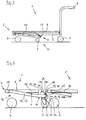
- the trolley 1 shown in Fig. 1 is, regarding its basic structure, known from the general state of the art.
- the trolley 1 Around the dolly 1 Stack 1 'to save space with other identical transport trolleys
- the trolley 1 has in a known manner an open, chassis 5 tapering towards the front, the front and rear is equipped with two swivel castors 6.
- Located on its back a sliding device carried by, for example, two upright bars 8.
- the chassis 5 carries a loading platform 9, the same to To be able to push trolleys 1, 1 'into each other, in a known manner mounted either front or rear to be raised about a horizontal axis is.
- a frame portion 10 Arranged centrally and starting from the front 2 of the chassis 5, extends backward a frame portion 10 which is in the area its free end 11 carries another swivel castor 7.
- a locking mechanism 17 is arranged, the is capable of arranged on the frame portion 10 castor 7 at Driving the trolley 1, 1 'on pivoting about its vertical To prevent swivel axis.
- the locking mechanism 17 can be known Be designed in such a way that this is only possible when driving the Trolley 1, 1 'is effective or in principle blocking in the Steering roller 7 engages and when stacking with another trolley 1 'is put out of function by the trolley 1' to be inserted. Preventing the pivoting mobility of the steering roller 7 facilitates how known to drive straight ahead of a loaded trolley 1, 1 '.
- the locking mechanism 17 has a Locking part 18 on one on the top 15 of the frame section 10 located, arranged transversely to the longitudinal direction of the trolley 1, 1 ' horizontal axis 19 is pivotally mounted.
- the locking part 18th is an angled structure, one in the sliding direction of the trolley 1, 1 'section 20 which rises obliquely upwards and then adjoins it in the sliding direction of the trolley 1, 1 'falling down Section 21, with its lower end 22 blocking in the Swivel castor 7 engages.
- the rising section 20 of the locking part 18 is curved downward in an arc shape to create a contact and contact surface 23 for the chassis 5 of a trolley 1 'to be inserted.
- the rising section 20 can also at its upper end be provided with a small rolling element on a cross to the direction of sliding of the trolley 1, 1 'located axis is rotatably mounted.
- the highest point 24 of the abutment and contact surface 23 is by the dimension A.
- the frame sections 10 are approximately V-shaped when viewed from above designed, cf. Fig. 5.
- the mounting portions 26 of the frame portion 10 are provided at both ends of the V-shaped frame 27, while the castor 7 and the locking mechanism 17 in that Are arranged area in which the two legs of the V-shaped Frame 27 collide.
- a baffle 16 is provided in the center, on which the locking element 18 with its abutment and contact surface 23 during the telescoping process slides along.
- the locking part 18 is behind the rear boundary 13 of the frame section 10, i.e. the rear one Limitation 25 of the locking part 18 is further from the front end 3 of the Trolley 1, 1 'removed as the rear boundary 13 of the frame section 10th
- Fig. 3 shows sections and in section the front areas of two space-saving nested transport trolley 1, 1 '.
- the kick-off and Contact surface 23 of the locking part 18 of the preceding transport vehicle 1 is on the underside 4 of the chassis 5 of the inserted trolley 1 'on. In the example, this is the baffle formed by a sheet 16.
- the locking part 18 is pivoted to the left in the drawing, so that the locking of the castor 7 of the trolley 1 is released is.
- the steering roller 7 can be in this position about its vertical pivot axis swivel. If more than two transport carriages 1, 1 'are pushed into one another, so are all, except for the last inserted trolley 1 ' remaining locking parts 18 and thus all remaining locking mechanisms 17th removed from their function.
- a stack of nested dolly cars 1, 1 ' can thus be moved effortlessly on curved tracks. It is very important if e.g. In self-service shops it is important to collect trolleys 1, 1 ' or move in batches for other reasons.
- FIG. 4 A further variant is shown in FIG. 4.
- a downward projection 28 which at Pushing two transport carriages 1, 1 'into one another the locking part 18 of a preceding one Trolley 1 for the purpose of unlocking the Swivel castor 7 pivoted.
- FIG. 5 shows a top view of the front 2 of the chassis 5 of the transport carriage 1 with the frame section 10, but without a loading platform 9. You can see the two apart fastening sections 26 of the frame section 10, which with the front spar 2 'of Chassis 5 fixed or pivotally connected about a horizontal axis are. Such arrangements are part of the prior art. Between the frame section 10, the baffle 16 is arranged on the chassis 5. In the rear area 12 of the frame section 10 are the locking mechanism 17 and the steering roller 7 arranged.
Landscapes
- Engineering & Computer Science (AREA)
- Chemical & Material Sciences (AREA)
- Combustion & Propulsion (AREA)
- Transportation (AREA)
- Mechanical Engineering (AREA)
- Handcart (AREA)
Applications Claiming Priority (2)
| Application Number | Priority Date | Filing Date | Title |
|---|---|---|---|
| DE19758052 | 1997-12-29 | ||
| DE19758052A DE19758052A1 (de) | 1997-12-29 | 1997-12-29 | Stapelbarer Transportwagen |
Publications (2)
| Publication Number | Publication Date |
|---|---|
| EP0927676A1 true EP0927676A1 (fr) | 1999-07-07 |
| EP0927676B1 EP0927676B1 (fr) | 2003-07-30 |
Family
ID=7853486
Family Applications (1)
| Application Number | Title | Priority Date | Filing Date |
|---|---|---|---|
| EP98119733A Expired - Lifetime EP0927676B1 (fr) | 1997-12-29 | 1998-10-20 | Chariot de transport emboítable |
Country Status (2)
| Country | Link |
|---|---|
| EP (1) | EP0927676B1 (fr) |
| DE (2) | DE19758052A1 (fr) |
Cited By (1)
| Publication number | Priority date | Publication date | Assignee | Title |
|---|---|---|---|---|
| GB2389084A (en) * | 2002-05-29 | 2003-12-03 | Cyril Moye | Trolley Stabiliser |
Families Citing this family (2)
| Publication number | Priority date | Publication date | Assignee | Title |
|---|---|---|---|---|
| NZ529228A (en) * | 2001-04-05 | 2005-12-23 | Brian John Higgins | Trolley wheel assembly |
| DE102021210439A1 (de) | 2021-09-20 | 2023-04-06 | Psa Automobiles Sa | Lastentransportfahrzeug und Fahrzeugverbund |
Citations (4)
| Publication number | Priority date | Publication date | Assignee | Title |
|---|---|---|---|---|
| DE2803003C3 (de) | 1978-01-20 | 1980-07-24 | Otto Reichelt Gmbh, 1000 Berlin | Transportwagen mit richtungsfeststellbaren Hinterrädern |
| WO1993025398A1 (fr) * | 1992-06-10 | 1993-12-23 | Lloyd Gerald E | Ensemble roue de guidage pour chariot et chariot ainsi equipe |
| US5669100A (en) * | 1993-07-15 | 1997-09-23 | Carpenter; Graham Scott | Castor locking device with freely pivotable curved tongue engagement |
| FR2759049A1 (fr) * | 1997-02-05 | 1998-08-07 | Leorat Roland | Chariot d'achat a pivot deverrouillable |
-
1997
- 1997-12-29 DE DE19758052A patent/DE19758052A1/de not_active Withdrawn
-
1998
- 1998-10-20 EP EP98119733A patent/EP0927676B1/fr not_active Expired - Lifetime
- 1998-10-20 DE DE59809152T patent/DE59809152D1/de not_active Expired - Fee Related
Patent Citations (4)
| Publication number | Priority date | Publication date | Assignee | Title |
|---|---|---|---|---|
| DE2803003C3 (de) | 1978-01-20 | 1980-07-24 | Otto Reichelt Gmbh, 1000 Berlin | Transportwagen mit richtungsfeststellbaren Hinterrädern |
| WO1993025398A1 (fr) * | 1992-06-10 | 1993-12-23 | Lloyd Gerald E | Ensemble roue de guidage pour chariot et chariot ainsi equipe |
| US5669100A (en) * | 1993-07-15 | 1997-09-23 | Carpenter; Graham Scott | Castor locking device with freely pivotable curved tongue engagement |
| FR2759049A1 (fr) * | 1997-02-05 | 1998-08-07 | Leorat Roland | Chariot d'achat a pivot deverrouillable |
Cited By (1)
| Publication number | Priority date | Publication date | Assignee | Title |
|---|---|---|---|---|
| GB2389084A (en) * | 2002-05-29 | 2003-12-03 | Cyril Moye | Trolley Stabiliser |
Also Published As
| Publication number | Publication date |
|---|---|
| DE19758052A1 (de) | 1999-07-01 |
| DE59809152D1 (de) | 2003-09-04 |
| EP0927676B1 (fr) | 2003-07-30 |
Similar Documents
| Publication | Publication Date | Title |
|---|---|---|
| EP0352647B1 (fr) | Chariot de transport empilable | |
| EP1003663B1 (fr) | Chariot de transport deplacable manuellement | |
| DE19855691B4 (de) | Gepäck- oder Einkaufswagen mit selbstverriegelnder Vorderradanordnung | |
| EP1590224B1 (fr) | Chariot de transport pousse manuellement | |
| DE3444969A1 (de) | Stapelbarer einkaufswagen | |
| DE68912317T2 (de) | Stapelbarer Einkaufswagen mit einer einziehbaren Ablage unter dem Transportkorb. | |
| EP0927676B1 (fr) | Chariot de transport emboítable | |
| EP1886894B1 (fr) | Chariot de transport pouvant être déplacé à la main | |
| EP0770535B1 (fr) | Chariot de transport emboítable | |
| EP0569988A2 (fr) | Chariot de transport pour objets de type palette | |
| EP0430058B1 (fr) | Chariot à bagages encastrables | |
| EP0905004B1 (fr) | Chariot d'achat emboítable | |
| DE3444278C2 (de) | Stapelbarer Einkaufswagen | |
| DE3442124A1 (de) | Von hand bewegbarer transportwagen | |
| EP3354536B1 (fr) | Chariot libre-service imbricable | |
| DE8433784U1 (de) | Von Hand bewegbarer Transportwagen | |
| DE3502194A1 (de) | Von hand bewegbarer transportwagen | |
| EP0891912A1 (fr) | Chariot de transport emboítable | |
| DE8903451U1 (de) | Mit entsprechenden Wagen schachtelbarer Schubgepäckwagen | |
| DE4205023A1 (de) | Transportkarre fuer unterfahrbare gegenstaende | |
| EP0734933B1 (fr) | Chariot d'achats emboítables | |
| DE7917706U1 (de) | Transportwagen | |
| EP1960246B1 (fr) | Chariot de transport deplaçable manuellement | |
| DE19806644A1 (de) | Stapelbarer Einkaufswagen | |
| DE8815152U1 (de) | Mit entsprechenden Wagen schachtelbarer Schubgepäckwagen |
Legal Events
| Date | Code | Title | Description |
|---|---|---|---|
| PUAI | Public reference made under article 153(3) epc to a published international application that has entered the european phase |
Free format text: ORIGINAL CODE: 0009012 |
|
| 17P | Request for examination filed |
Effective date: 19990503 |
|
| AK | Designated contracting states |
Kind code of ref document: A1 Designated state(s): DE FR GB |
|
| AX | Request for extension of the european patent |
Free format text: AL;LT;LV;MK;RO;SI |
|
| AKX | Designation fees paid | ||
| RBV | Designated contracting states (corrected) |
Designated state(s): AT BE CH LI |
|
| REG | Reference to a national code |
Ref country code: DE Ref legal event code: 8566 |
|
| RBV | Designated contracting states (corrected) |
Designated state(s): DE FR GB |
|
| GRAH | Despatch of communication of intention to grant a patent |
Free format text: ORIGINAL CODE: EPIDOS IGRA |
|
| GRAH | Despatch of communication of intention to grant a patent |
Free format text: ORIGINAL CODE: EPIDOS IGRA |
|
| GRAA | (expected) grant |
Free format text: ORIGINAL CODE: 0009210 |
|
| AK | Designated contracting states |
Designated state(s): DE FR GB |
|
| REG | Reference to a national code |
Ref country code: GB Ref legal event code: FG4D Free format text: NOT ENGLISH |
|
| REF | Corresponds to: |
Ref document number: 59809152 Country of ref document: DE Date of ref document: 20030904 Kind code of ref document: P |
|
| GBT | Gb: translation of ep patent filed (gb section 77(6)(a)/1977) |
Effective date: 20031119 |
|
| ET | Fr: translation filed | ||
| PLBE | No opposition filed within time limit |
Free format text: ORIGINAL CODE: 0009261 |
|
| STAA | Information on the status of an ep patent application or granted ep patent |
Free format text: STATUS: NO OPPOSITION FILED WITHIN TIME LIMIT |
|
| 26N | No opposition filed |
Effective date: 20040504 |
|
| PGFP | Annual fee paid to national office [announced via postgrant information from national office to epo] |
Ref country code: DE Payment date: 20061031 Year of fee payment: 9 |
|
| PGFP | Annual fee paid to national office [announced via postgrant information from national office to epo] |
Ref country code: GB Payment date: 20071022 Year of fee payment: 10 Ref country code: FR Payment date: 20071019 Year of fee payment: 10 |
|
| PG25 | Lapsed in a contracting state [announced via postgrant information from national office to epo] |
Ref country code: DE Free format text: LAPSE BECAUSE OF NON-PAYMENT OF DUE FEES Effective date: 20080501 |
|
| GBPC | Gb: european patent ceased through non-payment of renewal fee |
Effective date: 20081020 |
|
| REG | Reference to a national code |
Ref country code: FR Ref legal event code: ST Effective date: 20090630 |
|
| PG25 | Lapsed in a contracting state [announced via postgrant information from national office to epo] |
Ref country code: FR Free format text: LAPSE BECAUSE OF NON-PAYMENT OF DUE FEES Effective date: 20081031 |
|
| PG25 | Lapsed in a contracting state [announced via postgrant information from national office to epo] |
Ref country code: GB Free format text: LAPSE BECAUSE OF NON-PAYMENT OF DUE FEES Effective date: 20081020 |