EP0926314B1 - Structure d'etancheite pour turbines a gaz - Google Patents
Structure d'etancheite pour turbines a gaz Download PDFInfo
- Publication number
- EP0926314B1 EP0926314B1 EP98928571A EP98928571A EP0926314B1 EP 0926314 B1 EP0926314 B1 EP 0926314B1 EP 98928571 A EP98928571 A EP 98928571A EP 98928571 A EP98928571 A EP 98928571A EP 0926314 B1 EP0926314 B1 EP 0926314B1
- Authority
- EP
- European Patent Office
- Prior art keywords
- sealing
- inner shroud
- members
- portions
- seal
- Prior art date
- Legal status (The legal status is an assumption and is not a legal conclusion. Google has not performed a legal analysis and makes no representation as to the accuracy of the status listed.)
- Expired - Lifetime
Links
Images


Classifications
-
- F—MECHANICAL ENGINEERING; LIGHTING; HEATING; WEAPONS; BLASTING
- F01—MACHINES OR ENGINES IN GENERAL; ENGINE PLANTS IN GENERAL; STEAM ENGINES
- F01D—NON-POSITIVE DISPLACEMENT MACHINES OR ENGINES, e.g. STEAM TURBINES
- F01D11/00—Preventing or minimising internal leakage of working-fluid, e.g. between stages
- F01D11/001—Preventing or minimising internal leakage of working-fluid, e.g. between stages for sealing space between stator blade and rotor
-
- F—MECHANICAL ENGINEERING; LIGHTING; HEATING; WEAPONS; BLASTING
- F01—MACHINES OR ENGINES IN GENERAL; ENGINE PLANTS IN GENERAL; STEAM ENGINES
- F01D—NON-POSITIVE DISPLACEMENT MACHINES OR ENGINES, e.g. STEAM TURBINES
- F01D11/00—Preventing or minimising internal leakage of working-fluid, e.g. between stages
- F01D11/02—Preventing or minimising internal leakage of working-fluid, e.g. between stages by non-contact sealings, e.g. of labyrinth type
- F01D11/025—Seal clearance control; Floating assembly; Adaptation means to differential thermal dilatations
-
- F—MECHANICAL ENGINEERING; LIGHTING; HEATING; WEAPONS; BLASTING
- F01—MACHINES OR ENGINES IN GENERAL; ENGINE PLANTS IN GENERAL; STEAM ENGINES
- F01D—NON-POSITIVE DISPLACEMENT MACHINES OR ENGINES, e.g. STEAM TURBINES
- F01D11/00—Preventing or minimising internal leakage of working-fluid, e.g. between stages
- F01D11/08—Preventing or minimising internal leakage of working-fluid, e.g. between stages for sealing space between rotor blade tips and stator
- F01D11/12—Preventing or minimising internal leakage of working-fluid, e.g. between stages for sealing space between rotor blade tips and stator using a rubstrip, e.g. erodible. deformable or resiliently-biased part
- F01D11/127—Preventing or minimising internal leakage of working-fluid, e.g. between stages for sealing space between rotor blade tips and stator using a rubstrip, e.g. erodible. deformable or resiliently-biased part with a deformable or crushable structure, e.g. honeycomb
Definitions
- the present invention relates to a sealing apparatus for a gas turbine and more particularly relates to a sealing apparatus for a gas turbine in which clearance variations in a sealing structure intervening between the inner shroud members of stationary blades and the platforms of moving blades are eliminated to improve sealing performance.
- Figure 5 is a sectional view showing conventional sealing structure portions in a gas turbine.
- reference numeral 21 denotes a moving blade
- 22 denotes a platform thereof
- 23 denotes a sealing plate
- numeral 24 denotes a blade root portion.
- a plurality of moving blades 21 are mounted radially around a rotor by way of the respective root portions 24.
- Reference numeral 31 denotes a stationary blade disposed adjacent to the moving blade 21, and numeral 32 denotes an inner shroud member of the stationary blade 31.
- Reference numeral 33 denotes a cavity defined inside of the inner shroud member, and numeral 34 denotes an annular shaped seal ring.
- Reference numeral 35 denotes an air hole provided in the seal ring 34 through which the cavity 33 and a space intervening between the stationary blade 31 and the blade root portion 24 of the adjacent moving blade 21 are communicated with each other.
- Reference numeral 36 denotes a sealing portion provided in the seal ring 34, wherein a labyrinth seal or the like is adopted to seal the rotatable root portion 24.
- Reference numeral 37 denotes a honeycomb seal mounted on the inner shroud member at the upstream side thereof as viewed in the direction of the combustion gas flow
- numeral 38 denotes a honeycomb seal also mounted on the inner shroud member 32 at the downstream side thereof.
- These honeycomb seals 37 and 38 are disposed in the vicinity of rotor arm portions 25a and 25b of the platforms 22 of the adjacent moving blades 21, respectively, and provide resistance to air leaks to thereby provide sealing.
- FIG. 6 shows a portion D in Fig. 5 in detail.
- the honeycomb seal 38 having a large number of honeycomb cores is disposed at an end portion of the inner shroud member 32 in such a state that the open side of the honeycomb is positioned closely to a tip end portion of the rotor arm portion 25a of the platform 22.
- a clearance t between the honeycomb seal 38 and the rotor arm portion 25a is substantially 1 mm.
- the air 40 leaking at a high pressure from the cavity 33 flows out into a of a low-pressure combustion gas passage from a space defined between a side wall of the seal ring 34 provided at the stationary blade 31 and the sealing plate 23 of the moving blade 21 by way of the clearance t formed between the honeycomb seal 38 and the rotor arm portion 25a at the downstream side of the combustion gas flow.
- the high pressure leaking air 40 flows along the path mentioned above, resistance to its flow increases. Consequently, a sealing effect takes place between the honeycomb seal 38 and the rotor arm portion 25a which are disposed close to each other, whereby the high temperature combustion gas is prevented from entering the interior of the stationary blade 31.
- the leaking air flows out into a space between the honeycomb seal 37, provided at the stationary blade 31 and disposed at the upstream side of the combustion gas flow, and the rotor arm portion 25b, resulting in increased resistance to the flow of leaking air, whereby sealing is provided for the combustion gas passage.
- the conventional sealing structure for the gas turbine described above suffers a problem in that since the honeycomb seals 37 and 38 are mounted directly at the end portions of the inner shroud members 32 of the stationary blades 31, nonuniform variation occurs in the clearance t with respect to the circumferential dimension thereof due to deformation of the inner shroud members 32 after operation of the gas turbine, dimensional dispersion of the inner shroud members upon manufacturing or due to other causes.
- the rotor arm portions 25a and 25b of the platform 22 which rotate relative to the inner shroud members 32 are each of an annular shape and follow a circular path upon rotation, the clearances t formed between the honeycomb seals 38 and 37 mounted on the inner shroud members 32 and the rotor arm portions 25a and 25b of the platform 22 can not be controlled at all, thus giving rise to a problem.
- Figure 7 is a sectional view taken along the line E-E in Fig. 6.
- a plurality of inner shroud members 32 of the stationary blades 31 are mounted independent of one another in an annular array at an appropriate distance along a circumference, and are spaced from the circular rotor arm portion 25a by a predetermined distance.
- the honeycomb seal 38 is mounted on the inner shroud member 32, and the space between the honeycomb seal 38 and the rotor arm portion 25a represents the clearance t .
- the state of the inner shroud members 32 immediately after the manufacturing thereof is indicated by solid lines.
- the inner shroud members 32 and the stationary blades 31 undergo deformation due to rotation of the rotor arm portion 25a, as indicated by the broken lines.
- This deformation causes the honeycomb seal 38 to deviate from its desired position, which in turn brings about variation in the clearance between the honeycomb seal 38 and the rotor arm portion 25a. Accordingly, control of the clearance between the honeycomb seals 38 mounted on the inner shroud members 32 and the rotor arm portion 25a of the platform 22 is made impossible.
- US 5,630,703 discloses a cooling system for gas turbine engines.
- the cooling system comprises an axially extending plenum disposed inward of each blade dovetail and a thermal isolation chamber, formed by a seal body, disposed over the outer surface of each disk posts.
- the cooling system further includes an aft retention member forming in part an annular plenum in fluid flow communication with each of the axially extending plenums.
- US 3,945,758 which forms the preamble of claim 1, discloses a system for cooling and sealing gas turbine stator and rotor blade structures.
- Each of the stationary blades comprises an inner shroud portion.
- a web member is fixed by means of a bolt to this inner shroud portion.
- wall members on the downstream and upstream side of the web member are fixed by means of the bolt to the shroud and the web member.
- the downstream wall and the upstream stationary wall comprise abradable seal members, respectively. These seals are intended to restrict the flow of hot gases between the seals and respective shoulder portions of the blade roots of the moving blades.
- the wall members extend at front end portions and rear end portions, respectively, of the inner shroud member in an axial direction thereof.
- the present invention provides an apparatus according to claim 1. Preferred embodiments are defined by the dependent claims.
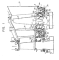
- FIG. 1 is a schematic view showing a sealing apparatus for a gas turbine according to an embodiment of the present invention, i.e., a mode for carrying out the invention.
- reference numeral 21 denotes a moving blade
- 22 denotes a platform thereof
- numeral 24 denotes a blade root portion.
- Reference numerals 11 and 12 denote rotor arm portions disposed, respectively, at the front and rear ends of the platform 22 as viewed in the axial direction, wherein the rotor arm portion 11 disposed on the upstream side of combustion gas flow is disposed at an inner position when compared with that of the conventional turbine, while the rotor arm portion 12 disposed on the downstream side is disposed at an outer position when compared with that of the conventional turbine.
- Reference numerals 13 and 14 denote sealing plates covering a shank portion, wherein the sealing plate 14 is provided with an integral arm portion 14a having fins 14b.
- Reference numeral 31 denotes a stationary blade
- 32 denotes an inner shroud member thereof
- 33 denotes a cavity formed inside of the inner shroud member 32
- numeral 34 denotes a sealing portion.
- a labyrinth seal and the like is adopted a the sealing portion 34, which is disposed close to and opposite the blade root portion 24 of the adjacent rotatable moving blade 21.
- Reference numeral 35 denotes an air hole through which the cavity 33 and the space around the adjacent moving blade 21 are communicated with each other.
- Reference numeral 1 denotes a seal ring of an annular shape which is provided with an arm portion 2 at the upstream side of the combustion gas flow.
- the arm portion 2 is disposed close to the end portion of the inner shroud member 32 and extends along a curved surface of the end portion, wherein a honeycomb seal 4b is mounted on a lower surface of the arm portion 2.
- an arm portion 3 is disposed at the downstream side of the combustion gas flow direction of the seal ring 1. This arm portion 3 is disposed so as to extend along the end portion of the inner shroud member 32, and a honeycomb seal 4a serving as the sealing member is mounted on the lower surface of the arm portion 3.
- FIG. 2 is a detailed view of a portion A in Fig. 1 and shows the downstream side of the inner shroud member 32 of the stationary blade 31.
- the seal ring 1 is mounted on the inner shroud members 32.
- the seal ring 1 is formed in an annular shape and divided into two parts.
- Each seal ring 1 has the arm portion 3 and a projection 5 at the side adjacent to the moving blade 21 and is fixedly secured to the inner shroud members 32 by means of bolts 6.
- the arm portion 3 projects toward the platform 22 and extends along the inner curved surface of the end portion of the inner shroud member 32, and the honeycomb seal 4a is mounted on the lower surface of the arm portion.
- a large number of downward opening honeycomb cores are disposed in the honeycomb seal 4a, and the rotor arm portion 11 of the platform 22 of the moving blade 21 is disposed opposite open surface of the honeycomb seal.
- a large number of fins 11a are disposed on the upper surface of the rotor arm portion 11 with a predetermined clearance t , e.g. 1 mm, relative to the honeycomb seal 4a.
- the sealing plate 13 of the moving blade 21 is provided with an arm 13a projecting toward the seal ring 1 to form a seal in cooperation with a projection 5 provided in association with the stationary blade 31.
- Figure 3 is a sectional view taken along the line C-C in Fig. 2.
- the annular arm portion 3 of the seal ring 1 is disposed at the inner side of a plurality of stationary blades 31 and the inner shrouds thereof which are independently disposed in a circular array, and the circular arm portion 3 is disposed so as to extend along the inner surfaces of the inner shroud members 32.
- the honeycomb seal 4a is mounted on the lower surface of the annular shaped arm portion 3 continuously in an annular form. Moreover, since the honeycomb seal 4a is bulky, it is mounted on the arm portion 3 being divided into two parts in the circumferential direction.
- the inner shroud members 32 in the state before the gas turbine is put into operation are depicted by solid lines. At this time, the inner shroud members 32 are disposed at respective predetermined positions circumferetially. On the other hand, after operation of the gas turbine begins, the inner shroud members are deformed at every stationary blade, as indicated by broken lines.
- the honeycomb seal 4a is mounted on the arm portion 3 of the seal ring 1 which is disposed separately and independently from the inner shroud members 32, as described previously, the honeycomb seal can remain unaffected by the deformation of the inner shroud members 32, and the clearance t between the honeycomb seal 4a and the fins 11a mounted on the rotor arm portion 11 of the platform 22, as shown in Fig. 2, can be maintained at a predetermined distance.
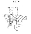
- FIG. 4 is a detailed view of a portion B in Fig. 1 and shows the inner shroud members 32 of the stationary blade 31 at the upstream side of the combustion gas flow.
- the seal ring 1 mounted at the inner side of the end portions of the inner shroud members 32 has a projecting arm portion 2 formed by bending the seal ring 1 approximately in an L-like shape along the curved surfaces of the inner shroud members, and the honeycomb seal 4b is mounted on the lower surface of the seal ring with the open surface of the honeycomb seal facing downward.
- the above mentioned sealing plate 14 is mounted on the platform 22 of the moving blade 21, and the sealing portion 14a of the sealing plate 14 projects to a position opposite the arm portion 2 which is provided in association with the inner shroud member 32. Fins 14b are provided on the sealing portion 14a and are disposed opposite the honeycomb seal 4b with a predetermined clearance t being maintained relative to the honeycomb seal 4b.
- the honeycomb seal 4b is also mounted on the arm portion 2 of the seal ring 1 disposed separately and independently from the inner shroud members 32, as described hereinbefore in conjunction with the relationship between the inner shroud members 32 and the honeycomb seal 4a mounted on the arm portion 3 with reference to Fig. 3, the honeycomb seal can remain unaffected by the deformation of the inner shroud members 32. Thereby, the clearance t intervening between the honeycomb seal 4b and the fins 14b of the sealing plate 14 mounted on the platform 22, as shown in Fig. 4, can be maintained at a predetermined distance.
- the high pressure leaking air 40 flows out from the cavity 33 into the low-pressure combustion gas passage through the space formed between the side wall of the seal ring 1 of the stationary blade 31 and the sealing plate 13 of the moving blade 21 by way of the clearance t formed between the honeycomb seal 4a and the fins 11a of the rotor arm portion 11 at the downstream side of the inner shroud member 32 of the stationary blade 31 of the gas flow (see Fig. 2).
- the high pressure leaking air 40 flows along the path mentioned above, resistance to its flow increases. Consequently, a sealing effect is brought about between the honeycomb seal 4a and the fins 11a disposed adjacent to each other, whereby the high temperature combustion gas is prevented from entering the interior of the stationary blade 31.
- the leaking air flows out through the space defined between the honeycomb seal 4b and the fins 14b of the sealing plate 14 at the downstream side of the moving blade 21, whereby sealing is provided for the combustion gas passage due to the increased resistance to the flow of leaking air.
- the inner shroud members 32 of the stationary blades 31 are deformed at every stationary blade after operation of the gas turbine begins, as indicated by broken lines in Fig. 3.
- the honeycomb seals 4a and 4b are mounted on the arm portions 2 and 3 of the annular shaped seal ring 1 which is split into two parts and provided separately and independently from the inner shroud members 32, deformation of the individual inner shroud members 32 or dispersion with respect to the mounting dimensions and the like exert no influence on the honeycomb seals 4a and 4b of the seal ring 1. Consequently, the sealing clearances t defined between the honeycomb seals 4a and 4b and the fins 11a and 14b, respectively, can be maintained at predetermined dimensions.
- the clearances t which are defined, respectively, between the honeycomb seals 4a and 4b and the fins 11a and 14b provided in association with the moving blade 21 and which are set at optimum dimensions upon design for manufacturing and assembling of the gas turbine can be maintained at the predetermined dimensions, notwithstanding deformation of the inner shroud members 32 after operation of the gas turbine begins.
- clearance control can be realized. Consequently, the honeycomb seal is directly mounted on the inner shroud member 32.
- the clearance mentioned above changes due to the deformation of the inner shroud member 32 after operation of the gas turbine begins. This problem can be solved with the structure according to the instant embodiment of the invention, whereby clearance control for the seal can be remarkably improved.
- the resistance to the flow of leaking air can be further increased by disposing the plurality of projecting fins 11a and 14b in association with the moving blade 21 opposite the honeycomb seals 4a and 4b. Since, the amount of leaking air can be decreased, the operating performance of the gas turbine can be enhanced.
- the arm portion 2 of the seal ring 1 shown in Fig. 4 may be constituted by split members to ensure ease of assembly.
- the seal ring 1 can be formed as an integral structure including the arm portions 2 and 3.
- the fins provided in association with the moving blade 21 may be mounted directly on the rotor arm portion 11 which is integral with the platform 22 or, alternatively, mounted on the sealing plate 13 or 14 provided separately and independently from the platform 22.
- the arm portions 2 and 3 provided in association with the inner shroud members 32 of the stationary blades 31 are disposed at an outer side, while the sealing portion 14a and the rotor arm portion 11a provided in association with the moving blades 21 are disposed at an inner side. Accordingly, the honeycomb seals 4a and 4b provided in association with the stationary blade 31 face inward while the fins 14b and 11a provided in association with the moving blade 21 face outward, and hence are disposed opposite each other.
Landscapes
- Engineering & Computer Science (AREA)
- Mechanical Engineering (AREA)
- General Engineering & Computer Science (AREA)
- Turbine Rotor Nozzle Sealing (AREA)
- Gasket Seals (AREA)
Claims (4)
- Appareil d'étanchéité pour turbine à gaz, comprenantdans lequel chacune desdites parties de bras (2, 3) disposées en association avec ladite bague d'étanchéité (1) est formée intégralement avec ladite bague d'étanchéité (1), caractérisé en ce que lesdits éléments d'étanchéité (4a, 4b) sont des joints en nids d'abeille.des parties de bras (2, 3) se projetant depuis une bague d'étanchéité (1) afin de fixer de manière inamovible des éléments de flasques internes (32) d'aubes directrices (31), respectivement, lesdites parties de bras s'étendant le long de parties d'extrémité avant et de parties d'extrémité arrière, respectivement, desdits éléments de flasques internes (32) dans une direction axiale de ceux-ci,des éléments d'étanchéité (4a, 4b) montés sur lesdites parties de bras (2, 3), respectivement, etdes parties d'extrémité de plates-formes (22) d'aubes mobiles (21) disposées de manière adjacente à au moins l'une de ladite partie d'extrémité avant et de ladite partie d'extrémité arrière, respectivement, dudit élément de flasque interne (32), afin de fermer un intérieur desdits éléments de flasques internes (32) par rapport à un passage de gaz de combustion grâce à la coopération desdites parties d'extrémité des plates-formes (22) des aubes mobiles (21) avec lesdits éléments d'étanchéité (4a, 4b),
- Appareil d'étanchéité pour turbine à gaz selon la revendication 1, dans lequel une projection (11a, 14b) est disposée de manière opposée audit élément d'étanchéité au niveau de chacune des parties d'extrémité de ladite plate-forme (22) de ladite aube mobile (21).
- Appareil d'étanchéité pour turbine à gaz selon la revendication 1, dans lequel les parties d'étanchéité sont disposées séparément des parties d'extrémité de ladite plate-forme (22) de ladite aube mobile adjacente, et dans lequel lesdits mécanismes d'étanchéité sont réalisés, respectivement, par le biais de la coopération desdites parties d'étanchéité et desdits éléments d'étanchéité (4a, 4b) montés sur lesdites parties de bras, respectivement.
- Appareil d'étanchéité pour turbine à gaz selon la revendication 3, dans lequel chacune desdites parties d'étanchéité prévues en association avec ladite aube mobile (21) est munie d'une projection disposée de manière opposée audit élément d'étanchéité (4a, 4b).
Applications Claiming Priority (3)
| Application Number | Priority Date | Filing Date | Title |
|---|---|---|---|
| JP16110097 | 1997-06-18 | ||
| JP16110097A JP3327814B2 (ja) | 1997-06-18 | 1997-06-18 | ガスタービンのシール装置 |
| PCT/JP1998/002722 WO1998058159A1 (fr) | 1997-06-18 | 1998-06-18 | Structure d'etancheite pour turbines a gaz |
Publications (3)
| Publication Number | Publication Date |
|---|---|
| EP0926314A1 EP0926314A1 (fr) | 1999-06-30 |
| EP0926314A4 EP0926314A4 (fr) | 2001-01-24 |
| EP0926314B1 true EP0926314B1 (fr) | 2004-12-22 |
Family
ID=15728613
Family Applications (1)
| Application Number | Title | Priority Date | Filing Date |
|---|---|---|---|
| EP98928571A Expired - Lifetime EP0926314B1 (fr) | 1997-06-18 | 1998-06-18 | Structure d'etancheite pour turbines a gaz |
Country Status (6)
| Country | Link |
|---|---|
| US (1) | US6152690A (fr) |
| EP (1) | EP0926314B1 (fr) |
| JP (1) | JP3327814B2 (fr) |
| CA (1) | CA2263642C (fr) |
| DE (1) | DE69828255T2 (fr) |
| WO (1) | WO1998058159A1 (fr) |
Cited By (1)
| Publication number | Priority date | Publication date | Assignee | Title |
|---|---|---|---|---|
| DE102010062087A1 (de) | 2010-11-29 | 2012-05-31 | Siemens Aktiengesellschaft | Strömungsmaschine mit Dichtstruktur zwischen drehenden und ortsfesten Teilen sowie Verfahren zur Herstellung dieser Dichtstruktur |
Families Citing this family (46)
| Publication number | Priority date | Publication date | Assignee | Title |
|---|---|---|---|---|
| AUPQ155799A0 (en) * | 1999-07-09 | 1999-08-05 | Coroneo, Minas Theodore | Therapeutic methods and uses |
| DE10019546B4 (de) * | 2000-04-20 | 2016-04-07 | Alstom Technology Ltd. | Dampfturbine mit einem einem Rotor und/oder einem Stator zugeordneten Schaufelträger |
| EP1167695A1 (fr) * | 2000-06-21 | 2002-01-02 | Siemens Aktiengesellschaft | Turbine à gaz et aube statorique pour une turbine à gaz |
| US6558114B1 (en) * | 2000-09-29 | 2003-05-06 | Siemens Westinghouse Power Corporation | Gas turbine with baffle reducing hot gas ingress into interstage disc cavity |
| JP4494658B2 (ja) * | 2001-02-06 | 2010-06-30 | 三菱重工業株式会社 | ガスタービンの静翼シュラウド |
| DE10295864D2 (de) * | 2001-12-14 | 2004-11-04 | Alstom Technology Ltd Baden | Gasturbinenanordnung |
| ITMI20021219A1 (it) * | 2002-06-05 | 2003-12-05 | Nuovo Pignone Spa | Dispositivo di supporto semplificato per ugelli di uno stadio di una turbina a gas |
| US6887039B2 (en) | 2002-07-10 | 2005-05-03 | Mitsubishi Heavy Industries, Ltd. | Stationary blade in gas turbine and gas turbine comprising the same |
| US6779972B2 (en) * | 2002-10-31 | 2004-08-24 | General Electric Company | Flowpath sealing and streamlining configuration for a turbine |
| DE10318852A1 (de) * | 2003-04-25 | 2004-11-11 | Rolls-Royce Deutschland Ltd & Co Kg | Hauptgaskanal-Innendichtung einer Hochdruckturbine |
| DE102004025692B4 (de) * | 2004-05-26 | 2006-05-11 | Mitsubishi Heavy Industries, Ltd. | Hartlötaufbau für ein abtragbares Dichtungsmaterial und Verfahren zum Herstellen eines solchen Hartlötaubaus |
| US7105219B2 (en) | 2004-05-27 | 2006-09-12 | Mitsubishi Heavy Industries, Ltd. | Brazing construction and method of brazing an abradable sealing material |
| US20060275106A1 (en) * | 2005-06-07 | 2006-12-07 | Ioannis Alvanos | Blade neck fluid seal |
| US20070273104A1 (en) * | 2006-05-26 | 2007-11-29 | Siemens Power Generation, Inc. | Abradable labyrinth tooth seal |
| GB2438858B (en) * | 2006-06-07 | 2008-08-06 | Rolls Royce Plc | A sealing arrangement in a gas turbine engine |
| US7500824B2 (en) * | 2006-08-22 | 2009-03-10 | General Electric Company | Angel wing abradable seal and sealing method |
| US20080061515A1 (en) * | 2006-09-08 | 2008-03-13 | Eric Durocher | Rim seal for a gas turbine engine |
| US8205335B2 (en) * | 2007-06-12 | 2012-06-26 | United Technologies Corporation | Method of repairing knife edge seals |
| US20090110548A1 (en) * | 2007-10-30 | 2009-04-30 | Pratt & Whitney Canada Corp. | Abradable rim seal for low pressure turbine stage |
| JP2010001841A (ja) * | 2008-06-20 | 2010-01-07 | Mitsubishi Heavy Ind Ltd | 動翼およびガスタービン |
| US8419356B2 (en) | 2008-09-25 | 2013-04-16 | Siemens Energy, Inc. | Turbine seal assembly |
| US8376697B2 (en) * | 2008-09-25 | 2013-02-19 | Siemens Energy, Inc. | Gas turbine sealing apparatus |
| US8388309B2 (en) * | 2008-09-25 | 2013-03-05 | Siemens Energy, Inc. | Gas turbine sealing apparatus |
| US8075256B2 (en) * | 2008-09-25 | 2011-12-13 | Siemens Energy, Inc. | Ingestion resistant seal assembly |
| US8162598B2 (en) * | 2008-09-25 | 2012-04-24 | Siemens Energy, Inc. | Gas turbine sealing apparatus |
| US8142141B2 (en) * | 2009-03-23 | 2012-03-27 | General Electric Company | Apparatus for turbine engine cooling air management |
| US8277172B2 (en) * | 2009-03-23 | 2012-10-02 | General Electric Company | Apparatus for turbine engine cooling air management |
| US9133732B2 (en) * | 2010-05-27 | 2015-09-15 | Siemens Energy, Inc. | Anti-rotation pin retention system |
| CN101886555A (zh) * | 2010-07-09 | 2010-11-17 | 兰州长城机械工程有限公司 | 烟气轮机转子叶片密封装置 |
| FR2977274B1 (fr) * | 2011-06-30 | 2013-07-12 | Snecma | Joint d'etancheite a labyrinthe pour turbine d'un moteur a turbine a gaz |
| US9416673B2 (en) * | 2012-01-17 | 2016-08-16 | United Technologies Corporation | Hybrid inner air seal for gas turbine engines |
| US9145788B2 (en) | 2012-01-24 | 2015-09-29 | General Electric Company | Retrofittable interstage angled seal |
| US9121298B2 (en) | 2012-06-27 | 2015-09-01 | Siemens Aktiengesellschaft | Finned seal assembly for gas turbine engines |
| US9039357B2 (en) | 2013-01-23 | 2015-05-26 | Siemens Aktiengesellschaft | Seal assembly including grooves in a radially outwardly facing side of a platform in a gas turbine engine |
| US9181816B2 (en) | 2013-01-23 | 2015-11-10 | Siemens Aktiengesellschaft | Seal assembly including grooves in an aft facing side of a platform in a gas turbine engine |
| US9068513B2 (en) | 2013-01-23 | 2015-06-30 | Siemens Aktiengesellschaft | Seal assembly including grooves in an inner shroud in a gas turbine engine |
| EP2759675A1 (fr) | 2013-01-28 | 2014-07-30 | Siemens Aktiengesellschaft | Agencement de turbine présentant un meilleur effet d'étanchéité au niveau d'un joint étanche |
| EP2759676A1 (fr) * | 2013-01-28 | 2014-07-30 | Siemens Aktiengesellschaft | Agencement de turbine présentant un meilleur effet d'étanchéité au niveau d'un joint étanche |
| US20150040567A1 (en) * | 2013-08-08 | 2015-02-12 | General Electric Company | Systems and Methods for Reducing or Limiting One or More Flows Between a Hot Gas Path and a Wheel Space of a Turbine |
| JP5852190B2 (ja) * | 2014-07-30 | 2016-02-03 | 三菱重工業株式会社 | 端壁部材及びガスタービン |
| JP5852191B2 (ja) * | 2014-07-30 | 2016-02-03 | 三菱重工業株式会社 | 端壁部材及びガスタービン |
| US10132182B2 (en) | 2014-11-12 | 2018-11-20 | United Technologies Corporation | Platforms with leading edge features |
| US10337345B2 (en) | 2015-02-20 | 2019-07-02 | General Electric Company | Bucket mounted multi-stage turbine interstage seal and method of assembly |
| US10633992B2 (en) | 2017-03-08 | 2020-04-28 | Pratt & Whitney Canada Corp. | Rim seal |
| IT202000013609A1 (it) | 2020-06-08 | 2021-12-08 | Ge Avio Srl | Componente di un motore a turbina con un insieme di deflettori |
| KR102601739B1 (ko) * | 2023-06-08 | 2023-11-10 | 터보파워텍(주) | 터빈용 인터스테이지 실 |
Citations (3)
| Publication number | Priority date | Publication date | Assignee | Title |
|---|---|---|---|---|
| US3945758A (en) * | 1974-02-28 | 1976-03-23 | Westinghouse Electric Corporation | Cooling system for a gas turbine |
| US5215435A (en) * | 1991-10-28 | 1993-06-01 | General Electric Company | Angled cooling air bypass slots in honeycomb seals |
| US5630703A (en) * | 1995-12-15 | 1997-05-20 | General Electric Company | Rotor disk post cooling system |
Family Cites Families (14)
| Publication number | Priority date | Publication date | Assignee | Title |
|---|---|---|---|---|
| FR597549A (fr) * | 1924-06-05 | 1925-11-23 | Dispositif pour obturer l'intervalle séparant la roue directrice de la roue mobile dans les turbines, et en particulier dans les turbines à vapeur ou à gaz | |
| BE792286A (fr) * | 1971-12-06 | 1973-03-30 | Gen Electric | Dispositif de retenue d'aubes sans boulon pour un rotor de turbomachin |
| US3824030A (en) * | 1973-07-30 | 1974-07-16 | Curtiss Wright Corp | Diaphragm and labyrinth seal assembly for gas turbines |
| US3989410A (en) * | 1974-11-27 | 1976-11-02 | General Electric Company | Labyrinth seal system |
| FR2552159B1 (fr) * | 1983-09-21 | 1987-07-10 | Snecma | Dispositif de liaison et d'etancheite de secteurs d'aubes de stator de turbine |
| JPS6088002A (ja) * | 1983-10-21 | 1985-05-17 | Nok Corp | ゴムラテツクスからの共沈体の製造法 |
| JPS6088002U (ja) * | 1983-11-24 | 1985-06-17 | 株式会社日立製作所 | ガスタ−ビン |
| JPH0651881B2 (ja) * | 1985-11-22 | 1994-07-06 | 株式会社島津製作所 | 焼結炉 |
| JPS62167802U (fr) * | 1986-04-15 | 1987-10-24 | ||
| GB8922339D0 (en) * | 1989-10-04 | 1989-11-22 | Rolls Royce Plc | Improvements in or relating to labyrinth seal structures |
| GB2251040B (en) * | 1990-12-22 | 1994-06-22 | Rolls Royce Plc | Seal arrangement |
| US5217348A (en) * | 1992-09-24 | 1993-06-08 | United Technologies Corporation | Turbine vane assembly with integrally cast cooling fluid nozzle |
| JPH06159099A (ja) * | 1992-11-25 | 1994-06-07 | Toshiba Corp | 軸流流体機械 |
| JPH0711907A (ja) * | 1993-06-29 | 1995-01-13 | Ishikawajima Harima Heavy Ind Co Ltd | タービンケーシング構造 |
-
1997
- 1997-06-18 JP JP16110097A patent/JP3327814B2/ja not_active Expired - Fee Related
-
1998
- 1998-06-18 CA CA002263642A patent/CA2263642C/fr not_active Expired - Fee Related
- 1998-06-18 US US09/242,529 patent/US6152690A/en not_active Expired - Lifetime
- 1998-06-18 WO PCT/JP1998/002722 patent/WO1998058159A1/fr active IP Right Grant
- 1998-06-18 EP EP98928571A patent/EP0926314B1/fr not_active Expired - Lifetime
- 1998-06-18 DE DE69828255T patent/DE69828255T2/de not_active Expired - Lifetime
Patent Citations (3)
| Publication number | Priority date | Publication date | Assignee | Title |
|---|---|---|---|---|
| US3945758A (en) * | 1974-02-28 | 1976-03-23 | Westinghouse Electric Corporation | Cooling system for a gas turbine |
| US5215435A (en) * | 1991-10-28 | 1993-06-01 | General Electric Company | Angled cooling air bypass slots in honeycomb seals |
| US5630703A (en) * | 1995-12-15 | 1997-05-20 | General Electric Company | Rotor disk post cooling system |
Cited By (2)
| Publication number | Priority date | Publication date | Assignee | Title |
|---|---|---|---|---|
| DE102010062087A1 (de) | 2010-11-29 | 2012-05-31 | Siemens Aktiengesellschaft | Strömungsmaschine mit Dichtstruktur zwischen drehenden und ortsfesten Teilen sowie Verfahren zur Herstellung dieser Dichtstruktur |
| WO2012072384A1 (fr) | 2010-11-29 | 2012-06-07 | Siemens Aktiengesellschaft | Turbomachine comportant une structure d'étanchéité entre des pièces tournantes et des pièces fixes ainsi que procédé de fabrication de ladite structure d'étanchéité |
Also Published As
| Publication number | Publication date |
|---|---|
| CA2263642C (fr) | 2002-08-20 |
| WO1998058159A1 (fr) | 1998-12-23 |
| DE69828255D1 (de) | 2005-01-27 |
| CA2263642A1 (fr) | 1998-12-23 |
| DE69828255T2 (de) | 2005-12-22 |
| EP0926314A1 (fr) | 1999-06-30 |
| JP3327814B2 (ja) | 2002-09-24 |
| US6152690A (en) | 2000-11-28 |
| EP0926314A4 (fr) | 2001-01-24 |
| JPH116446A (ja) | 1999-01-12 |
Similar Documents
| Publication | Publication Date | Title |
|---|---|---|
| EP0926314B1 (fr) | Structure d'etancheite pour turbines a gaz | |
| US7008185B2 (en) | Gas turbine engine turbine nozzle bifurcated impingement baffle | |
| US4425079A (en) | Air sealing for turbomachines | |
| US4187054A (en) | Turbine band cooling system | |
| US6932568B2 (en) | Turbine nozzle segment cantilevered mount | |
| US6969233B2 (en) | Gas turbine engine turbine nozzle segment with a single hollow vane having a bifurcated cavity | |
| EP1798381B1 (fr) | Contrôle thermique de l'anneau de turbine pour régulation active de jeu dans les turbines à gaz | |
| US6983608B2 (en) | Methods and apparatus for assembling gas turbine engines | |
| US4337016A (en) | Dual wall seal means | |
| US8277177B2 (en) | Fluidic rim seal system for turbine engines | |
| US6183193B1 (en) | Cast on-board injection nozzle with adjustable flow area | |
| US4184689A (en) | Seal structure for an axial flow rotary machine | |
| US6926495B2 (en) | Turbine blade tip clearance control device | |
| JP2617707B2 (ja) | 回転機械用ステータ組立体 | |
| US7234918B2 (en) | Gap control system for turbine engines | |
| US6109867A (en) | Cooled turbine-nozzle vane | |
| JP4124552B2 (ja) | 高圧コンプレッサの固定子 | |
| JPH02199202A (ja) | タービン機械の隙間制御装置 | |
| JPH0379524B2 (fr) | ||
| US20190085699A1 (en) | Turbine rotor comprising a ventilation spacer | |
| EP3926141B1 (fr) | Aube de stator de turbine à gaz dotée d'un élément d'étanchéité et procédé de modification d'une aube de stator de turbine à gaz | |
| US11015483B2 (en) | High pressure compressor flow path flanges with leak resistant plates for improved compressor efficiency and cyclic life | |
| JPH0660702U (ja) | ガスタービン分割環のシール構造 | |
| JP4284643B2 (ja) | ガスタービンのタービンノズル冷却構造 | |
| EP0949404A1 (fr) | Anneau de guidage composé par des aubes singulières vissées |
Legal Events
| Date | Code | Title | Description |
|---|---|---|---|
| PUAI | Public reference made under article 153(3) epc to a published international application that has entered the european phase |
Free format text: ORIGINAL CODE: 0009012 |
|
| 17P | Request for examination filed |
Effective date: 19990218 |
|
| AK | Designated contracting states |
Kind code of ref document: A1 Designated state(s): CH DE FR GB IT LI |
|
| A4 | Supplementary search report drawn up and despatched |
Effective date: 20001212 |
|
| AK | Designated contracting states |
Kind code of ref document: A4 Designated state(s): CH DE FR GB IT LI |
|
| 17Q | First examination report despatched |
Effective date: 20021122 |
|
| GRAP | Despatch of communication of intention to grant a patent |
Free format text: ORIGINAL CODE: EPIDOSNIGR1 |
|
| GRAS | Grant fee paid |
Free format text: ORIGINAL CODE: EPIDOSNIGR3 |
|
| GRAA | (expected) grant |
Free format text: ORIGINAL CODE: 0009210 |
|
| AK | Designated contracting states |
Kind code of ref document: B1 Designated state(s): CH DE FR GB IT LI |
|
| REG | Reference to a national code |
Ref country code: GB Ref legal event code: FG4D |
|
| REG | Reference to a national code |
Ref country code: CH Ref legal event code: NV Representative=s name: WILLIAM BLANC & CIE CONSEILS EN PROPRIETE INDUSTRI Ref country code: CH Ref legal event code: EP |
|
| REF | Corresponds to: |
Ref document number: 69828255 Country of ref document: DE Date of ref document: 20050127 Kind code of ref document: P |
|
| PLBE | No opposition filed within time limit |
Free format text: ORIGINAL CODE: 0009261 |
|
| STAA | Information on the status of an ep patent application or granted ep patent |
Free format text: STATUS: NO OPPOSITION FILED WITHIN TIME LIMIT |
|
| ET | Fr: translation filed | ||
| 26N | No opposition filed |
Effective date: 20050923 |
|
| REG | Reference to a national code |
Ref country code: CH Ref legal event code: PFA Owner name: MITSUBISHI HEAVY INDUSTRIES, LTD. Free format text: MITSUBISHI HEAVY INDUSTRIES, LTD.#5-1, MARUNOUCHI 2-CHOME, CHIYODA-KU,#TOKYO 100-8315 (JP) -TRANSFER TO- MITSUBISHI HEAVY INDUSTRIES, LTD.#5-1, MARUNOUCHI 2-CHOME, CHIYODA-KU,#TOKYO 100-8315 (JP) |
|
| REG | Reference to a national code |
Ref country code: CH Ref legal event code: PCAR Free format text: NOVAGRAAF SWITZERLAND SA;CHEMIN DE L'ECHO 3;1213 ONEX (CH) |
|
| PGFP | Annual fee paid to national office [announced via postgrant information from national office to epo] |
Ref country code: GB Payment date: 20140618 Year of fee payment: 17 |
|
| PGFP | Annual fee paid to national office [announced via postgrant information from national office to epo] |
Ref country code: CH Payment date: 20140612 Year of fee payment: 17 Ref country code: IT Payment date: 20140618 Year of fee payment: 17 |
|
| PGFP | Annual fee paid to national office [announced via postgrant information from national office to epo] |
Ref country code: FR Payment date: 20140609 Year of fee payment: 17 |
|
| PG25 | Lapsed in a contracting state [announced via postgrant information from national office to epo] |
Ref country code: IT Free format text: LAPSE BECAUSE OF NON-PAYMENT OF DUE FEES Effective date: 20150618 |
|
| REG | Reference to a national code |
Ref country code: CH Ref legal event code: PL |
|
| GBPC | Gb: european patent ceased through non-payment of renewal fee |
Effective date: 20150618 |
|
| REG | Reference to a national code |
Ref country code: FR Ref legal event code: ST Effective date: 20160229 |
|
| PG25 | Lapsed in a contracting state [announced via postgrant information from national office to epo] |
Ref country code: CH Free format text: LAPSE BECAUSE OF NON-PAYMENT OF DUE FEES Effective date: 20150630 Ref country code: GB Free format text: LAPSE BECAUSE OF NON-PAYMENT OF DUE FEES Effective date: 20150618 Ref country code: LI Free format text: LAPSE BECAUSE OF NON-PAYMENT OF DUE FEES Effective date: 20150630 |
|
| PG25 | Lapsed in a contracting state [announced via postgrant information from national office to epo] |
Ref country code: FR Free format text: LAPSE BECAUSE OF NON-PAYMENT OF DUE FEES Effective date: 20150630 |
|
| PGFP | Annual fee paid to national office [announced via postgrant information from national office to epo] |
Ref country code: DE Payment date: 20170613 Year of fee payment: 20 |
|
| REG | Reference to a national code |
Ref country code: DE Ref legal event code: R071 Ref document number: 69828255 Country of ref document: DE |