EP0925751A1 - Spiess-Zusatzvorrichtung zum Kochen von Nahrungsmitteln - Google Patents
Spiess-Zusatzvorrichtung zum Kochen von Nahrungsmitteln Download PDFInfo
- Publication number
- EP0925751A1 EP0925751A1 EP98403299A EP98403299A EP0925751A1 EP 0925751 A1 EP0925751 A1 EP 0925751A1 EP 98403299 A EP98403299 A EP 98403299A EP 98403299 A EP98403299 A EP 98403299A EP 0925751 A1 EP0925751 A1 EP 0925751A1
- Authority
- EP
- European Patent Office
- Prior art keywords
- rotisserie
- accessory according
- flanges
- flange
- rotisserie accessory
- Prior art date
- Legal status (The legal status is an assumption and is not a legal conclusion. Google has not performed a legal analysis and makes no representation as to the accuracy of the status listed.)
- Withdrawn
Links
- 235000013305 food Nutrition 0.000 title claims description 9
- 238000010411 cooking Methods 0.000 title claims description 5
- 235000021168 barbecue Nutrition 0.000 description 3
- 206010061218 Inflammation Diseases 0.000 description 2
- 230000004054 inflammatory process Effects 0.000 description 2
- 238000004519 manufacturing process Methods 0.000 description 2
- 241000251468 Actinopterygii Species 0.000 description 1
- 230000000903 blocking effect Effects 0.000 description 1
- 238000004140 cleaning Methods 0.000 description 1
- 230000007423 decrease Effects 0.000 description 1
- 239000004519 grease Substances 0.000 description 1
- 239000004615 ingredient Substances 0.000 description 1
- 238000009434 installation Methods 0.000 description 1
- 235000013372 meat Nutrition 0.000 description 1
- 239000002184 metal Substances 0.000 description 1
- 238000003756 stirring Methods 0.000 description 1
Images

Classifications
-
- A—HUMAN NECESSITIES
- A47—FURNITURE; DOMESTIC ARTICLES OR APPLIANCES; COFFEE MILLS; SPICE MILLS; SUCTION CLEANERS IN GENERAL
- A47J—KITCHEN EQUIPMENT; COFFEE MILLS; SPICE MILLS; APPARATUS FOR MAKING BEVERAGES
- A47J37/00—Baking; Roasting; Grilling; Frying
- A47J37/04—Roasting apparatus with movably-mounted food supports or with movable heating implements; Spits
- A47J37/047—Roasting apparatus with movably-mounted food supports or with movable heating implements; Spits with rotating drums or baskets
Definitions
- the invention relates to a rotisserie accessory for cooking food, especially for ovens, roasters, barbecues or the like.
- Rotisserie is a particularly common use in ovens or roasters as in barbecues.
- the rotisserie is for roasting pieces of meat, or fish, or even skewers.
- the inventor also sought a device which allows with a rotisserie classic, to cook food in bulk or in pieces.
- a rotisserie accessory for cooking food comprising a container formed on the one hand, of an envelope at least partly perforated and closed on itself and on the other hand, two lateral flanges arranged to be crossed by the spit of the rotisserie on which at least one of said flanges can be secured in rotation.
- the inventor sought and developed a device which is particularly easy to manufacture, to assemble and disassemble, store and clean.
- the inventor designed a rotisserie accessory of the aforementioned type, with a cylindrical container with a polygon base, but which is in particular remarkable in that said envelope is in the form of two rigid parts at least one of which has at least two faces and which are provided combined hooking means intended to ensure assembly and disassembly at will.
- each part is constituted by a perforated sheet, at least one of which is folded to form at least two faces forming a dihedral, while preferably, the polygonal base of the container has 2 n sides, as does each lateral flange, and each part constitutes an half-shell with n faces.
- the base of the container is hexagonal.
- the openings of the part of the openwork envelope each have an oblong shape and are staggered relative to each other to others.
- the means for hooking the two parts together are formed by legs and slots respectively.
- At least one of the side flanges is removably mounted on a blank of the envelope, the latter and the said flange or flanges being provided with combined means of attachment, while the means of attachment of the flange (s) on the envelope are constituted by legs and slots respectively and according to a mode embodiment, at least one of said attachment tabs for at least the flange to fasten in rotation on the spindle, have an L or T cutout.
- At least one of the flanges is also perforated.
- the pin is secured in rotation on at least one of the flanges by means of a drive means which is fixed on said spindle and which has a shape of a two-wing stirrup at least one of which is T-shaped and which are intended to come into engagement with said flange in lights arranged therein so as to be able to ensure a locking in translation and in rotation whatever the direction.
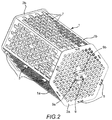
- the container shown consists of an outer envelope 1 and two lateral flanges 2a and 2b, for example of nickel-plated metal, said flanges therefore having here hexagonal shapes.
- the envelope 1 here consists of two half-shells 1a, 1b with three faces each, which can be seen more specifically in Figure 2.
- the two half-shells 1a and 1b are easily fixed together, for example by lugs such as 3 on the half-shell 1b and conjugate slots 4 on the other half-shell 1a.
- the flanges 2a and 2b are fixed here in a similar manner by means of lugs 5 provided on the lateral edges of each half-shell 1a, 1b and of slots 6 formed on the flanges as the drawings clearly show.
- the tabs 3 for assembling the two half-shells 1a, 1b have an L-shaped cutout, ensuring easy mounting by a last axial translational movement while the tabs 5 for assembling the flanges here present a cut out in T.
- legs 3 and 5 could be simple legs rectangular, in particular for reasons of simplification, with or without double folding for hanging, retaining and positioning can be done at less in part using the very elasticity of each half-shell.
- the legs 3 could have a T-shaped cutout, and / or the legs 5 an L-shaped cutout.
- the shape of the legs 5 in L or T turns out to be interesting for a locking in rotation since it is through at least one flange that the whole is rotated.
- the openings 7 of the half-shells 1a, 1b are here oblong and staggered as the drawings clearly show, while the openings 8 of the flanges 2a, 2b are in the example shown in circular form.
- Each half-shell 1a, 1b comes from a simple sheet folded to present several faces (here three faces for each half-shell, two contiguous faces forming then an angle of 120 ° between them). Each sheet is also perforated, like the show the drawings well.
- the flanges 2a, 2b are also here simple sheets openwork.
- Such a design allows in particular, as already said or suggested, a treatment easy surfaces if desired, easy cleaning with possibility of placed in conventional dishwashers and stacked storage of two parts inside each other, etc.
- the spindle (not shown) passes through the lateral flanges 2a, 2b, for example by a central opening, while it is secured in rotation using here an original drive means 9 provided to cooperate with one of the flanges (here 2a) and on which, for example, can be inserted radially a screw for locking of the spindle.
- the drive means 9, as can be seen in the drawings, has the shape of a two-wing stirrup 9a, 9b.
- Each wing 9a, 9b is furthermore profiled in T as can be seen on wing 9b of figure 1.
- Each wing of the drive means 9 is intended to engage in a corresponding light 10a, 10b formed in the flange concerned 2a (FIG. 1).
- Such a drive means eliminates the need for a blocking of the pin on the other flange.
- the general shape of the container can of course be otherwise than the one shown (pentagonal, octagonal or other, but preferably with an even number of sides for almost symmetry of the two parts to be assembled).
- attachment means can be otherwise (hooks, etc.), as well as the means for securing the spindle in rotation.
Landscapes
- Engineering & Computer Science (AREA)
- Food Science & Technology (AREA)
- Food-Manufacturing Devices (AREA)
Applications Claiming Priority (2)
| Application Number | Priority Date | Filing Date | Title |
|---|---|---|---|
| FR9716460A FR2772582B1 (fr) | 1997-12-24 | 1997-12-24 | Accessoire de tournebroche pour la cuisson des aliments |
| FR9716460 | 1997-12-24 |
Publications (1)
| Publication Number | Publication Date |
|---|---|
| EP0925751A1 true EP0925751A1 (de) | 1999-06-30 |
Family
ID=9515094
Family Applications (1)
| Application Number | Title | Priority Date | Filing Date |
|---|---|---|---|
| EP98403299A Withdrawn EP0925751A1 (de) | 1997-12-24 | 1998-12-24 | Spiess-Zusatzvorrichtung zum Kochen von Nahrungsmitteln |
Country Status (2)
| Country | Link |
|---|---|
| EP (1) | EP0925751A1 (de) |
| FR (1) | FR2772582B1 (de) |
Cited By (1)
| Publication number | Priority date | Publication date | Assignee | Title |
|---|---|---|---|---|
| FR2887421A1 (fr) * | 2005-06-27 | 2006-12-29 | Jean Francois Dupard | Panier de cuisson s'utilisant sur un tourne-br oche pour un four a chaleur tournante |
Citations (4)
| Publication number | Priority date | Publication date | Assignee | Title |
|---|---|---|---|---|
| DE2040077A1 (de) * | 1969-08-29 | 1971-03-04 | Philips Nv | Geraet zum Erhitzen von Speisen |
| CH603130A5 (en) | 1976-06-11 | 1978-08-15 | Therma Ag | Oven container for cooking bulk food |
| EP0140237A2 (de) * | 1983-10-14 | 1985-05-08 | Wopex V.O.F. | Vorrichtung zum Erhitzen von Grillgut |
| FR2703234A1 (fr) | 1993-03-31 | 1994-10-07 | Levy Philippe | Dispositif pour la cuisson de denrées alimentaires surgelées ou congelées . |
-
1997
- 1997-12-24 FR FR9716460A patent/FR2772582B1/fr not_active Expired - Fee Related
-
1998
- 1998-12-24 EP EP98403299A patent/EP0925751A1/de not_active Withdrawn
Patent Citations (4)
| Publication number | Priority date | Publication date | Assignee | Title |
|---|---|---|---|---|
| DE2040077A1 (de) * | 1969-08-29 | 1971-03-04 | Philips Nv | Geraet zum Erhitzen von Speisen |
| CH603130A5 (en) | 1976-06-11 | 1978-08-15 | Therma Ag | Oven container for cooking bulk food |
| EP0140237A2 (de) * | 1983-10-14 | 1985-05-08 | Wopex V.O.F. | Vorrichtung zum Erhitzen von Grillgut |
| FR2703234A1 (fr) | 1993-03-31 | 1994-10-07 | Levy Philippe | Dispositif pour la cuisson de denrées alimentaires surgelées ou congelées . |
Cited By (1)
| Publication number | Priority date | Publication date | Assignee | Title |
|---|---|---|---|---|
| FR2887421A1 (fr) * | 2005-06-27 | 2006-12-29 | Jean Francois Dupard | Panier de cuisson s'utilisant sur un tourne-br oche pour un four a chaleur tournante |
Also Published As
| Publication number | Publication date |
|---|---|
| FR2772582A1 (fr) | 1999-06-25 |
| FR2772582B1 (fr) | 2000-02-11 |
Similar Documents
| Publication | Publication Date | Title |
|---|---|---|
| CA3037236C (fr) | Appareil de cuisson du type friteuse a air chaud | |
| WO2000030511A1 (fr) | Recipient de cuisson pour cuiseur a la vapeur | |
| EP0272173B1 (de) | Schwingbare Käfigmutter | |
| EP3542689A1 (de) | Rührzusatzteil für ein elektrohaushaltsgerät zur essenszubereitung, das mit leicht entfernbarem/n schneebesen ausgestattet ist | |
| FR2774221A1 (fr) | Boitier a encastrer dans une quelconque paroi, notamment pour appareil electrique | |
| FR2704609A1 (fr) | Ensemble de fixation de panneau à actionnement rapide. | |
| FR2587423A1 (fr) | Plaque tournante pour fours a micro-ondes | |
| EP0935324B1 (de) | Eckpfosten für Schaltschrank und damit ausgerüsteter Schaltschrank | |
| EP0925751A1 (de) | Spiess-Zusatzvorrichtung zum Kochen von Nahrungsmitteln | |
| EP1400195B1 (de) | Haushaltsgerät aus scharnierartig verbundenen Rostelementen | |
| EP3542688B1 (de) | Zubehör für kulinarisches gerät zum mischen von niedrigen mengen von nahrungsmittelzubereitung | |
| EP1926192B1 (de) | Gehäuse für Trennwand in Trockenbauweise, mit axial fixierten Laschen und axial verschiebbaren Außenstützen | |
| EP0942675B1 (de) | Deckel mit griff-knopf | |
| EP2978347B1 (de) | Ofen | |
| EP0792608B1 (de) | Scharnier für Elektrokochplatten und Kochgerät mit Scharnier | |
| EP1072811A1 (de) | Haltevorrichtung für zwei ringförmige Federn der Synchronsperre in einer Synchronisationsnabe geeignet für Synchronisiereinrichtungen bei Kraftfahrzeug-Getrieben | |
| FR2687133A1 (fr) | Conteneur a dechets equipe d'une charniere perfectionnee. | |
| EP0290418A2 (de) | Deckel für ein Kochgefäss | |
| EP0857448A1 (de) | Grillrost aus scharnierartig verbundenen Rostelementen | |
| BE658206A (de) | ||
| FR2618196A1 (fr) | Roue libre autocentreuse a paliers lateraux munie d'un dispositif de solidarisation axiale des paliers par elements rapportes. | |
| FR2809945A3 (fr) | Rotissoire polyvalente | |
| FR2478956A2 (fr) | Perfectionnements apportes aux recipients utilisables pour exposer un produit, tel que des graines, a l'action de la chaleur | |
| FR2527432A1 (fr) | Barbecue a volets lateraux articules et amovibles | |
| FR3058879B1 (fr) | Plateau pour recouvrir une plaque de cuisson |
Legal Events
| Date | Code | Title | Description |
|---|---|---|---|
| PUAI | Public reference made under article 153(3) epc to a published international application that has entered the european phase |
Free format text: ORIGINAL CODE: 0009012 |
|
| AK | Designated contracting states |
Kind code of ref document: A1 Designated state(s): BE CH ES FR IT LI |
|
| AX | Request for extension of the european patent |
Free format text: AL;LT;LV;MK;RO;SI |
|
| 17P | Request for examination filed |
Effective date: 19991115 |
|
| AKX | Designation fees paid |
Free format text: BE CH ES FR IT LI |
|
| STAA | Information on the status of an ep patent application or granted ep patent |
Free format text: STATUS: THE APPLICATION IS DEEMED TO BE WITHDRAWN |
|
| 18D | Application deemed to be withdrawn |
Effective date: 20010703 |
|
| REG | Reference to a national code |
Ref country code: DE Ref legal event code: 8566 |