EP0925583B1 - Aufnahme- und/oder wiedergabesystem mit magnetbandcassette mit kupplungselement - Google Patents
Aufnahme- und/oder wiedergabesystem mit magnetbandcassette mit kupplungselement Download PDFInfo
- Publication number
- EP0925583B1 EP0925583B1 EP98901465A EP98901465A EP0925583B1 EP 0925583 B1 EP0925583 B1 EP 0925583B1 EP 98901465 A EP98901465 A EP 98901465A EP 98901465 A EP98901465 A EP 98901465A EP 0925583 B1 EP0925583 B1 EP 0925583B1
- Authority
- EP
- European Patent Office
- Prior art keywords
- pull
- coupling
- cassette
- recording
- reel
- Prior art date
- Legal status (The legal status is an assumption and is not a legal conclusion. Google has not performed a legal analysis and makes no representation as to the accuracy of the status listed.)
- Expired - Lifetime
Links
- 230000008878 coupling Effects 0.000 title claims abstract description 224
- 238000010168 coupling process Methods 0.000 title claims abstract description 224
- 238000005859 coupling reaction Methods 0.000 title claims abstract description 224
- 238000003780 insertion Methods 0.000 claims description 20
- 230000037431 insertion Effects 0.000 claims description 20
- 238000000034 method Methods 0.000 claims description 14
- 238000010276 construction Methods 0.000 description 5
- 230000014759 maintenance of location Effects 0.000 description 2
- 230000000694 effects Effects 0.000 description 1
- 230000002401 inhibitory effect Effects 0.000 description 1
Images
Classifications
-
- G—PHYSICS
- G11—INFORMATION STORAGE
- G11B—INFORMATION STORAGE BASED ON RELATIVE MOVEMENT BETWEEN RECORD CARRIER AND TRANSDUCER
- G11B23/00—Record carriers not specific to the method of recording or reproducing; Accessories, e.g. containers, specially adapted for co-operation with the recording or reproducing apparatus ; Intermediate mediums; Apparatus or processes specially adapted for their manufacture
- G11B23/02—Containers; Storing means both adapted to cooperate with the recording or reproducing means
- G11B23/04—Magazines; Cassettes for webs or filaments
- G11B23/08—Magazines; Cassettes for webs or filaments for housing webs or filaments having two distinct ends
- G11B23/107—Magazines; Cassettes for webs or filaments for housing webs or filaments having two distinct ends using one reel or core, one end of the record carrier coming out of the magazine or cassette
-
- G—PHYSICS
- G11—INFORMATION STORAGE
- G11B—INFORMATION STORAGE BASED ON RELATIVE MOVEMENT BETWEEN RECORD CARRIER AND TRANSDUCER
- G11B15/00—Driving, starting or stopping record carriers of filamentary or web form; Driving both such record carriers and heads; Guiding such record carriers or containers therefor; Control thereof; Control of operating function
- G11B15/60—Guiding record carrier
- G11B15/66—Threading; Loading; Automatic self-loading
- G11B15/67—Threading; Loading; Automatic self-loading by extracting end of record carrier from container or spool
- G11B15/672—Extracting end of record carrier from container or single reel
-
- G—PHYSICS
- G11—INFORMATION STORAGE
- G11B—INFORMATION STORAGE BASED ON RELATIVE MOVEMENT BETWEEN RECORD CARRIER AND TRANSDUCER
- G11B15/00—Driving, starting or stopping record carriers of filamentary or web form; Driving both such record carriers and heads; Guiding such record carriers or containers therefor; Control thereof; Control of operating function
- G11B15/60—Guiding record carrier
- G11B15/66—Threading; Loading; Automatic self-loading
- G11B15/67—Threading; Loading; Automatic self-loading by extracting end of record carrier from container or spool
- G11B15/674—Threading or attaching end of record carrier on or to single reel
Definitions
- the invention relates to a recording and reproducing system, comprising a recording and/or reproducing device and a cassette adapted to be inserted into the recording and/or reproducing device, which cassette comprises a rectangular parallelepiped housing having two mutually parallel main walls, in which housing a magnetic tape is accommodated, and in which the cassette accommodates a supply reel for storing the magnetic tape, which supply reel has a reel hub to which the magnetic tape is connected at one end, and further accommodates a coupling element, to which the magnetic tape is connected at its other end and which can be positioned into a coupling position in the cassette with the aid of positioning means, and in which a tape transport path has been defined in the recording and/or reproducing device, which tape transport path extends from a compartment for receiving the inserted cassette, via a magnetic head for scanning the magnetic tape and provided in the recording and/or reproducing device, to a rotationally drivable take-up reel for taking up the magnetic tape and provided in the recording and/or reproducing device, which take-up reel has a reel
- the invention further relates to a recording and/or reproducing device adapted to receive a cassette, which cassette comprises a rectangular parallelepiped housing having two mutually parallel main walls and accommodates a magnetic tape, and in which device a tape transport path for a magnetic tape has been defined, which tape transport path extends from a compartment for receiving an inserted cassette, via a magnetic head for scanning a magnetic tape, to a rotationally drivable take-up reel for taking up a magnetic tape and having a reel hub to which a pull-out tape is connected at its end nearest the take-up reel, which pull-out tape can be guided along the tape transport path, and is connected to a pull-out element at its other end which is remote from the take-up reel, which pull-out element can be held in a standby position with the aid of holding means and is adapted to be coupled to a coupling element of an inserted cassette, so as to pull such a coupling element and a magnetic tape out of an inserted cassette in a pull-out direction and up to the take-up
- the invention further relates to a cassette, which comprises a rectangular parallelepiped housing having two mutually parallel main walls and which accommodates a magnetic tape, and which comprises a supply reel for storing the magnetic tape, which supply reel has a reel hub to which the magnetic tape is connected at one end, and further comprises a coupling element, to which the magnetic tape is connected at its other end and which can be positioned into a coupling position in the cassette with the aid of positioning means, wherein the coupling element of the cassette comprises coupling means which are adapted to automatically establish, without any additional means being required, a coupling to coupling means of a pull-out element of a recording and/or reproducing device during a relative movement - which occurs between the cassette and a pull-out element of the recording and/or reproducing device in a direction of movement transverse to the main walls of the cassette, at least towards the end of the insertion of the cassette into a recording and/or reproducing device when the cassette inserted in order to put the cassette into operation -, during which. relative movement the coupling
- a recording and/or reproducing system of the type defined in the first paragraph and a recording and/or reproducing device of the type defined in the second paragraph are commercially available and are thus known.
- a cassette of the type defined in the third paragraph is known from the document US-A-4.335.858.
- US-A-4 335 858 discloses a system where a leader block of the tape in the cassette is attached to a pull-out finger during the vertical movement of the cassette when the cassette is inserted in the recorder. The pull-out finger together with the block is moved into the take-up reel by a pull-out tape which runs in a special guide.
- the pull-out element which is connected to the pull-out tape of the device, is formed by an end portion of the pull-out tape, which has a leading part formed with undercuts and which has a substantially elongate rectangular aperture adapted to cooperate with a separate actuating mechanism accommodated in the known device, this separate actuating mechanism enabling the end portion of the pull-out tape - i.e. the pull-out element of the pull-out tape - to be held in its standby position.
- the coupling element of the known cassette is formed by a further pull-out tape which is connected to the magnetic tape and which at the location of its free end has a substantially oval or elliptical aperture adapted to cooperate with the undercut leading part of the end portion of the pull-out tape of the device.
- the pull-out element formed by the end portion of the pull-out tape of the device should not only be held in its standby position by means of the separate actuating device but also has the drawback that, after the known cassette has been loaded into the known device of the system, said pull-out element should be moved from the standby position into a coupling position, during which movement the undercut leading part of the end portion of the pull-out tape is moved through the oval aperture in the further pull-out tape of the cassette, after which by means of the actuating device the leading part is held in such a position that, when the take-up reel of the known device is subsequently driven and, as a result of this, the pull-out tape of the device is driven, the undercuts in the leading part of this pull-out tape engage against the boundaries of the oval aperture in the further pull-out tape of the cassette, the undercuts in the leading part of the pull-out tape of the device engaging behind the further pull-out tape of the cassette and thereby providing a coupling between the pull-out tape of the device and
- the know device and the known cassette it is therefore necessary that the known device of the known system comprises a separate actuating device for moving the pull-out element formed by the end portion of the pull-out tape from its standby position into its coupling position.
- a separate actuating device represents a substantial expense and also involves the risk that a correct and reliable coupling between the pull-out tape of the device and the further pull-out tape of the cassette is no longer guaranteed after a longer operating time.
- a recording and/or reproducing system of the type defined in the first paragraph is characterized in that the recording and/or reproducing device comprises actuating means capable of producing a relative movement - in a direction of movement oriented transversely to the main walls of the cassette - between the cassette and the pull-out element of the recording and/or reproducing device, which pull-out element is held in its standby position with the aid of the holding means, during an insertion process of the cassette, at least towards the end of the insertion process, and the coupling element of the cassette and the pull-out element of the recording and/or reproducing device comprise coupling means which are adapted to automatically establish a coupling, without any additional means being required, during said relative movement in which the coupling element of the cassette is positioned in its coupling position with the aid of the positioning means and the pull-out element of the recording and/or reproducing device is held in its standby position with the aid of the holding means.
- the measures in accordance with the invention as defined above ensure in a particularly simple and, consequently, cheap manner that for coupling the pull-out element of the device and the coupling element of the cassette no additional means apart from these two elements themselves are required because these two elements are coupled automatically without any additional means towards the end of a loading cycle of a cassette in accordance with the invention into a recording and/or reproducing device in accordance with the invention.
- a recording and/or reproducing system in accordance with the invention having the characteristic features defined in the appendant Claim 5 it has further proved to be very advantageous if in addition the measures defined in the appendant Claim 6 are taken.
- the retaining means serve not only for retaining the pull-out element but also for guiding the pull-out element when its movement in the pull-out direction begins.
- a recording and/or reproducing device of the type defined in the second paragraph is characterized in that actuating means have been provided which are capable of producing a relative movement - in a direction of movement oriented transversely to the main walls of a cassette - between a cassette and the pull-out element of the recording and/or reproducing device, which pull-out element is held in its standby position with the aid of the holding means, during an insertion process of the cassette, at least towards the end of the insertion process, and the pull-out element of the recording and/or reproducing device comprises coupling means which are adapted to automatically establish a coupling, without any additional means being required, during said relative movement in which the pull-out element is held in its standby position with the aid of the holding means.
- Such a recording and/or reproducing device in accordance with the invention has advantages corresponding to those set forth hereinbefore for a recording and/or reproducing system in accordance with the invention as defined in Claim 1.
- a cassette of the type defined in the third paragraph is characterized in that the coupling means of the coupling element of the cassette are formed by a coupling pin which projects from the coupling element transversely to the mains walls of the cassette and which is engageable in a coupling hole in such a pull-out element of a recording and/or reproducing device.
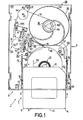
- FIGS 1 to 4 show a recording and reproducing system 1, hereinafter briefly referred to as the system 1.
- the system 1 comprises a recording and reproducing device 2, hereinafter briefly referred to as the device 2, and a cassette 3, which can be loaded into the device 2.
- the cassette 3 has a rectangular parallelepided housing 4, which - as is visible in Figure 2 - comprises a tray-shaped lower housing section and a likewise tray-shaped upper housing section 6.
- the cassette 3 is shown with the upper housing section 6 removed to expose the parts accommodated in the cassette 3.
- the housing 4 of the cassette 3 has two main walls 7 and 8 parallel to one another, i.e. a bottom wall 7 and an upper wall 8, as well as four side walls 9, 10, 11 and 12, which interconnect the two mains walls 7 and 8.
- the cassette 3 accommodates a magnetic tape 13.
- the cassette 3 comprises a supply reel 15.
- the supply reel 15 has a reel hub 16 to which the magnetic tape 13 is connected at one end in a manner, not shown.
- the cassette 3 further accommodates a coupling element 17, whose construction will be described in detail hereinafter.
- the magnetic tape 13 is connected to the coupling element 17 at its other end.
- the positioning means 18 comprise two positioning walls 19 and 20, which project from the bottom wall 7 of the cassette 3, the wall 19 being straight and the positioning wall 20 being shaped as an arc of circle, which positioning walls together form a wedge-like configuration adapted to the cross-sectional shape of the coupling element 17.
- the positioning means 18 have positioning walls corresponding in shape to the positioning walls 19 and 20 and projecting from the upper wall 8 of the cassette 3.
- the supply reel 15 is movable parallel to the orientation of its reel axis 21 from a rest position, in which the supply reel 15 lies on the bottom wall 9, into a drive position, in which the supply reel 15 has been lifted off the bottom wall 9.
- the drive position of the supply reel 15 the supply reel 15 is rotationally drivable about the reel axis 21.
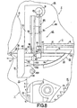
- the supply reel 15 is lifted off the bottom wall 9 of the cassette 3 by means of a reel drive device 27 provided in the device 2 and shown in Figure 1.
- the reel drive device 27 is mounted on a substantially plate-shaped chassis 28 of the device 2 and can be brought into operational engagement with the reel hub 16 of the supply reel 15 through an aperture, not shown, in the bottom wall 9 of the cassette 3.
- a tape transport path 29 has been defined for the magnetic tape 13.
- the tape transport path 29 extends from a compartment 30 for receiving the inserted cassette 3 to a take-up reel 38, which is rotationally drivable by means of a reel drive motor, which is secured to the chassis 28 and is not shown in the Figures, via a tape guide roller 31, which is mounted on the chassis 38 so as to be rotatable about a spindle 32, via a magnetic head 33 provided in the device 2 to scan the magnetic tape 13, and via a further tape guide roller 34, which is mounted for rotation about a spindle 35, the spindle 35 being carried by a lever 36, which is supported on the chassis 28 so as to be pivotable about a spindle 37.
- this magnetic head 33 is a so-called multi-track magnetic head by means of which a plurality of tracks which adjoin one another on the magnetic tape 13 in the longitudinal direction of the magnetic tape 13 and which, in addition, is adjustable in height by means of an actuating device HM transversely to the longitudinal direction of the magnetic tape 13, but which will not be described in any further detail because it is not relevant in the present case.
- the take-up reel 38 has a reel hub 39 from which a reel flange 40 extends in radial directions at its side which faces the chassis 28.
- an pull-out tape 41 is connected to the reel hub 39 of the take-up reel 38 at its end nearest the take-up reel 38.
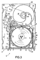
- the pull-out tape 41 can be guided along the tape transport path 29 described above, as is apparent from Figures 1 and 3.
- the pull-out tape 41 is connected to an pull-out element 42 in a manner not shown.
- the pull-out element 42 can be held in a standby position shown in Figures 1, 3, 8 and 9 with the aid of holding means 43 provided in the device 2.
- the pull-out element 42 can be coupled to the coupling element 17 of the inserted cassette 3 when this coupling element is in its coupling position.
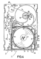
- the take-up reel 38 - which is effected by means of the reel drive motor not shown - the coupling element 17 and, consequently, the magnetic tape 13 can be pulled out of the inserted cassette 3 in an pull-out direction indicated by an arrow 44 in Figures 1, 3, 4, 5, 6, 7, 8 and 9 and can be pulled along the tape transport path 29 up to the take-up reel 38 with the aid of the take-up reel 38, the pull-out tape 41, the pull-out element 42 and the coupling element 17 of the inserted cassette 3, when coupled to the pull-out element 42.
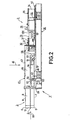
- the device 2 in the system 1 comprises a movable cassette holder 45, whose construction is apparent from Figure 2.
- the movable cassette holder 45 constitutes actuating means capable of producing a relative movement - in a direction of movement indicated by an arrow 46 in Figure 2 and oriented transversely to the main walls 7 and 8 of the cassette 3 - between the cassette 3 and the pull-out element 42 of the device 2, which element is held in its standby position with the aid of the holding means 43, during an insertion process of the cassette 3, at least towards the end of the insertion process.
- this relative movement is effected by lowering the cassette 3 towards the chassis 28 of the device 2 in a direction indicated by an arrow 46.
- the movable cassette holder 45 comprises an upper wall 47, two side walls 48, which project from the upper wall 47 towards the chassis 28, and two strip-shaped bottom wall sections 49, which each project from a side wall 48 and are directed towards the other side wall 48.
- the two bottom wall sections 49 carry a cassette 3 inserted into the cassette holder 45, a spring not shown in Figure 2 and connected to the upper wall 47 urging the inserted cassette 3 against the bottom wall sections 49 in order to guarantee a reliable positioning and holding of the cassette 3 in the cassette
- Two actuating rollers 50 and 51 project laterally from each of the side walls 48 of the movable cassette holder 45.
- the actuating rollers 50 and 51 engage inclined actuating slots 52 and 53 formed in the two side flanges 54 and 55 of an essentially U-shaped actuating slide 56 whose web 57, which extends parallel to the chassis 28, is guided so as to he movable parallel to the direction of insertion of the cassette 3 into the cassette holder 45, as indicated by an arrow 60 in Figures 1 and 2, with the aid of guide rollers which are rotatably supported in the chassis 28 and of which the two guide rollers 58 and 59 are visible in Figure 1.
- the web 57 has an aperture 61 to allow the passage of the reel drive device 27.
- the actuating rollers 50 which both project laterally from the two side walls 48 of the cassette holder 45 and which are situated nearer the loading aperture of the device 2 for the passage of the cassette 3, each engage a guide slot 63 formed in a side wall portion 62 of the chassis 28.
- the two guide slots 63 of which only one guide slot 63 is visible in Figure 2, guide the cassette holder 45 so as to be slidable in a direction parallel to that indicated by the arrow 46.
- the actuating slide 56 cooperates with a latching lever 64, which is supported on the chassis 28 so as to be pivotable about a spindle 65.
- the latching lever 64 is movable between a latching position shown in Figure 1 and a release position shown in Figures 3 and 4.
- a first return spring acts on the latching lever 64 and tends to keep the latching lever 64 in its latching position.
- the latching lever 64 has a resilient arm 66 which projects into the path of movement of the cassette 3 during insertion of this cassette into the movable cassette holder 45.
- the latching lever 64 further comprises a latching projection 67, which faces a latching stop 68 of the actuating slide 56.
- a second return spring acts upon the actuating slide 56 and exerts a spring-load on the actuating slide 56 against the direction of insertion, so that the latching stop 68 of the actuating slide 56 is resiliently urged against the latching projection 67 of the latching lever 64 when the latching lever 64 is in its latching position shown in Figure 1.
- a user should move the actuating projection 69 of the actuating slide 56 in the direction indicated by the arrow 60, the actuating slide 56 then being moved in the direction indicated by the arrow 60 opposed by the force of the second return spring which acts upon this slide and the cassette holder 45 being moved away from the chassis 28 via the actuating slots 52 and 53 and the actuating rollers 50 and 51 in a direction opposite to that indicated by the arrow 46.
- the latching lever 64 is pivoted back into its latched position shown in Figure 1 in the clockwise direction under the influence of the first return spring which acts upon this lever, in which latched position the latching projection 67 of the lever blocks the actuating slide 56 via the latching stop 68 of the actuating slide 56.
- the resilient arm 66 of the latching lever 64 causes the cassette 3 to be moved slightly out of the cassette holder 45, i.e. out of the device 2, so that the cassette 3 can readily be removed.
- the coupling element 17 of the cassette 3 and the pull-out element 42 of the device 2 advantageously also comprise coupling means 70 which are adapted to automatically establish a coupling, without additional means being required, during said relative movement in which the coupling element 17 of the cassette 3 is positioned in its coupling position with the aid of the positioning means 18 and the pull-out element 42 of the device 2 is held in its standby position with the aid of the holding means 43.
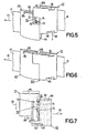
- coupling means 70 reference is made, in particular, to Figures 5 and 7.
- the coupling means 70 of the coupling element 17 and of the pull-out element 42 are formed by a coupling pin 71, which is connected to the coupling element 17 and which projects from the coupling element 17 parallel to said direction of movement indicated by the arrow 46 and, consequently, transversely to the mains walls 7 and 8 of the cassette 3, and by a coupling hole 72, which is formed in the pull-out element 42 and which extends parallel to said direction of movement indicated by the arrow 46 and, consequently, transversely to the mains walls 7 and 8 of the cassette 3.
- the coupling pin 71 can be introduced into the coupling hole 72 as indicated by the arrow 46.
- the coupling pin 71 has a distal portion 74 which is thicker than its proximal portion 73 which adjoins the coupling element 17.
- a spring-loaded latching element 75 is disposed, which in the present case is very simply formed by a blade spring having a V-shaped free end portion and which engages behind the distal portion 74 of the coupling pin 71 when the coupling pin 71 is introduced into the coupling hole 72, which situation is not shown in the Figures but is quite evident.
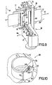
- the holding means 43 provided for the pull-out element 43 in the device 2 comprise a carrier lever 77 which is pivotable about a pivot 76.
- the pivot 76 extends parallel to the direction of said relative movement indicated by the arrow 46 and is mounted in the chassis 28, from which it projects in the afore-mentioned direction.
- the carrier lever 77 is connected to a substantially U-shaped holding element 78, which comprises two holding limbs 79, which extend transversely to the pivot 76 and of which only the upper holding limb 79 is visible in Figures 8 and 9, and a connecting limb 80, which interconnects the two holding limbs 79 and which extends parallel to the pivot 76.
- each of the two holding limbs 79 carries a guide rib 81 which projects towards the other holding limb 79 and of which only the upper guide rib 81 is visible in Figure 9.
- the longitudinal directions of the two guide ribs 81 correspond to the pull-out direction 44.
- the pull-out element 42 has two guide grooves 82 and 83 adapted to cooperate with the two guide ribs 81 for the purpose of guiding and holding the pull-out element 42.
- the coupling element 17 has two clearance grooves 84 and 85, which correspond to the two guide grooves 82 and 83 of the pull-out element 42 and which - as soon as the coupling element 17 and the pull-out element 42 are coupled as shown in Figure 6 - are disposed in line with the guide grooves 82 and 83 of the pull-out element 41 parallel to the pull-out direction 44. This guarantees that the coupling element 17 is withdrawn from the cassette 3 in a reliable manner and without being obstructed by the guide ribs 81.
- the two guide grooves 82 and 83 of the pull-out element 42 are each bounded by a bounding wall 86 or 87, respectively, at their ends nearer the pull-out tape 41, which bounding walls extend transversely to the pull-out direction 44.
- the travel of the pull-out element 42 in a direction opposite to the pull-out direction 44 can be limited because the two bounding walls 86 and 87 abut against the guide ribs 81 during a movement of the pull out element 42 in a direction opposite to the pull-out direction 44.
- a movable latching element 88 is connected to the carrier lever 77 of the holding means 43.
- the latching element 88 of the holding means 43 is formed by a wire spring having an offset portion.
- the wire spring forming the latching element 88 has one end 89 inserted into a recess in the pivot 76 and its central portion is passed over a projection 90 on the carrier lever 77, so that the wire spring is pre-tensioned, thereby causing a further portion 91 of the wire spring to abut against an L-shaped hold-down member 92 in the absence of a cassette 3, the wire spring constituting the latching element 88 then assuming a latching position.
- the wire spring constituting the latching element 88 is movable from this latching position into a release position, shown in Figure 9, by means of the cassette 3 during said relative movement in the direction indicated by the arrow 46.
- the pull-out element 42 comprises latching means 93 adapted to cooperate with the latching element 88 of the holding means 43.
- the latching means 93 of the pull-out element 42 are constituted by a recess formed in the pull-out element.
- the pull-out element 42 When the latching element 88 is in its latching position, which is not directly discernible in the Figures, the pull-out element 42, when in its standby position, is locked against a movement in the pull-out direction 88 with the aid of the latching element 88 of the holding means 43 and the latching means 93 of the pull-out element 42.
- the latching element 88 is moved from its latching position into its release position shown in Figure 9 by means of the cassette 4 via its substantially U-shaped free end 94, only when a cassette 3 has been loaded into the device 2, in which case the relevant portion of the latching element 88 is moved out of the recess forming the latching means 93 of the pull-out element 42, thus enabling the pull-out element 42 to be moved in the pull-out direction 44.
- the plastic carrier lever 77 comprises an integral bar spring 95 whose free end 96 abuts against a stop pin 97 which projects from the chassis 31.
- the bar spring 95 can resiliently load the carrier lever 77 and, consequently, the U-shaped holding element 78, which is integral with the carrier lever 77, in the direction indicated by an arrow 98 in Figure 8.
- the carrier lever 77 and the holding means 43 can be held in the holding position shown in Figure 8 with the aid of means not shown. In this holding position of the holding means 43 the pull-out element 42 is in its standby position.
- the holding means 43 Another advantageous feature of the holding means 43 is that the holding limb 79 of the U-shaped holding element 78 carries an actuating projection 99, which projects from the holding limb 79 substantially in a direction opposite to the pull-out direction 44 and from which a substantially circularly cylindrical actuating pin 100 projects.
- the actuating projection 99 i.e. by means of the actuating pin 100 which projects from this actuating projection 99, the coupling element 17 disposed in the inserted cassette 3 can be moved to the positioning means 18 for the coupling element 17. This movement of the coupling element 17 to the positioning means 18 is performed during insertion of the cassette 3 into the movable cassette holder 45, namely towards the end of this insertion process.
- the actuating pin 100 By means of the actuating pin 100 the actuating projection 99 and, consequently, the U-shaped holding element 78 as well as the carrier lever 77 are moved in a direction opposite to the direction indicated by the arrow 98 and opposed by the force of the bar spring 95 out of the standby position into a press-on position, not shown in Figure 8, in which the bar spring 95, whose free end 96 acts upon the stop pin 97, exerts a spring force on the actuating pin 100 via the carrier lever 77, the U-shaped holding element 78 and the actuating projection 99, which spring force is transmitted to the coupling element 17 via the wall portion 102 so that the coupling element 17 is urged into the positioning means 18 by spring force and is thus positioned properly into its coupling position before the coupling element 17 is moved towards the pull-out element 42 in the direction indicated by the arrow 46 and before the coupling means 70 of the coupling element 17 and of the pull-out element 42 engage with one another to effect coupling.
- a positioning wedge 105 which engages the recess 104 in the reel hub 39, is attached to the reel hub 39.
- the invention is not limited to the embodiment described by way of example in the foregoing.
- a variety of differently constructed means are available for the implementation of the positioning means for the coupling element of a cassette as well as for the implementation of the holding means for holding the pull-out element of a device.
Claims (27)
- Aufzeichnungs- und/oder Wiedergabesystem (1) mit einer Aufzeichnungsund/oder Wiedergabeeinrichtung (2) und einer Kassette (3), die dazu vorgesehen ist, in die Aufzeichnungs- und/oder Wiedergabeeinrichtung eingeführt zu werden, wobei diese Kassette (3) ein quaderförmiges Gehäuse (4) aufweist mit zwei zueinander parallelen Hauptwänden (7, 8), das einem Magnetband (13) Unterkunft bietet und wobei die Kassette (3) eine Speicherspule (15) aufweist zum Speichern des Magnetbandes (13), wobei diese Spule (15) eine Nabe (16) aufweist, mit der das Magnetband (13) an einem Ende desselben befestigt ist, und weiterhin ein Kupplungselement (17) aufweist, mit dem das Magnetband (13) an dem anderen Ende verbunden ist und das mit Hilfe von Positionierungsmitteln (18) in eine Kupplungslage in der Kassette (3) positioniert werden kann, und wobei eine Bandtransportstrecke (29) in der Aufzeichnungs- und/oder Wiedergabeeinrichtung (2) definiert worden ist, wobei diese Bandtransportstrecke (29) sich von einem Abteil (30) zum Empfangen der eingegebenen Kassette (3) über einen Magnetkopf (33) zum Abtasten des Magnetbandes (13) und vorgesehen in der Aufzeichnungs- und/oder Wiedergabeeinrichtung (2), zu einer drehbar antreibbaren Aufwickelspule (38) erstreckt zum Aufwickeln des Magnetbandes (13) und vorgesehen in der Aufzeichnungs- und/oder5 Wiedergabeeinrichtung (2), wobei diese Aufwickelspule (38) eine Spulennabe (39) aufweist, mit der ein heraus gezogenes Band (41) mit dem Ende verbunden ist, das der Aufwickelspule (38) am nächsten liegt, wobei dieses heraus gezogenes Band (41) an dem anderen Ende, das weiter von der Aufwickelspule (38) entfernt liegt, an der Bandtransportstrecke (29) entlang einem Ausziehelement (42) zugeführt wird, wobei dieses Ausziehelement (42) mit Hilfe von Haltemitteln (43), vorgesehen in der Aufzeichnungs- und/oder Wiedergabeeinrichtung (2), in einer Bereitschaftslage gehalten werden kann, und in der Bereitschaftslage mit dem Kupplungselement (17) der eingegebenen Kassette (3) in der Kupplungslage des Kupplungselementes (17) gekuppelt werden kann, und zwar derart, dass das Kupplungselement (17) und das Magnetband (13) aus der eingegebenen Kassette (3) in einer Ausziehrichtung (44) herausgezogen werden kann und über die Bandtransportstrecke (29) dadurch zu der Aufwikkelspule (38) gezogen werden kann, dass die Aufwickelspule (38) drehbar angetrieben wird, und zwar mit Hilfe der Aufwickelhaspel (38), des herausgezogenen Bandes (41), des Ausziehelementes (42) und des Kupplungselementes (17) der eingegebenen Kassette (3), wobei dieses Kupplungselement (17) mit dem Ausziehelement (42) gekuppelt worden ist, dadurch gekennzeichnet, dass die Aufzeichnungs- und/oder Wiedergabeeinrichtung (2) Betätigungsmittel (45) aufweist, die imstande sind, eine relative Verlagerung zu erzeugen - in einer Bewegungsrichtung (46) quer zu den Hauptwänden (7, 8) der Kassette (3) - zwischen der Kassette (3) und dem Ausziehelement (42) der Aufzeichnungs- und/oder Wiedergabeeinrichtung (2), wobei dieses Ausziehelement (42) während eines Einführungsvorgangs der Kassette (3) wenigstens gegen Ende des Einführungsvorgangs, mit Hilfe der Haltemittel (43) in der Bereitschaftslage gehalten wird, und das Kupplungselement (17) der Kassette (3) und das Ausziehelement (42) der Aufzeichnungs- und/oder Wiedergabeeinrichtung (2) Kupplungsmittel (70) aufweisen, dies dazu vorgesehen sind, automatisch eine Kupplung zu schaffen, ohne dass dazu zusätzliche Mittel erforderlich sind, wobei während der genannten relativen Verlagerung, wobei das Kupplungselement (17) der Kassette (3) mit Hilfe der Positionierungsmittel (18) in die Kupplungslage gebracht wird, und wobei das Ausziehelement (42) der Aufzeichnungs- und/oder Wiedergabeeinrichtung (2) mit Hilfe der Haltemittel (43) in der Bereitschaftslage gehalten wird.
- Aufzeichnungs- und/oder Wiedergabesystem (1) nach Anspruch 1, dadurch gekennzeichnet, dass die Kupplungsmittel (70) des Kupplungselementes (77) und des Ausziehelementes (42) durch einen Kupplungsstift (71) gebildet wird, der mit dem einen Element (17) der genannten zwei Elemente (17, 42) verbunden ist und sich von diesem Element (17) parallel zu der genannten Bewegungsrichtung (46) und folglich quer zu den Hauptwänden (7, 8) der Kassette (3) erstreckt, sowie durch eine Kupplungsöffnung (72) gebildet wird, die in dem anderen Element (42) der genannten zwei Elemente (17, 42) vorgesehen ist und sich parallel zu der genannten Bewegungsrichtung (46) und folglich quer zu den Hauptwänden (7, 8) der Kassette (3) erstreckt, wobei der Kupplungsstift (71) während der genannten relativen Verlagerung mit der Kupplungsöffnung (72) zusammenarbeiten kann.
- Aufzeichnungs- und/oder Wiedergabesystem (1) nach Anspruch 2, dadurch gekennzeichnet, dass der Kupplungsstift (71) mit dem Kupplungselement (77) der Kassette (3) verbunden ist und die Kupplungsöffnung (72) in dem Ausziehelement (42) der Aufzeichnungs- und/oder Wiedergabeeinrichtung (2) vorgesehen ist.
- Aufzeichnungs- und/oder Wiedergabesystem (1) nach Anspruch 3, dadurch gekennzeichnet, dass der Kupplungsstift (71) einen entfernt liegenden Teil (73) aufweist, der dicker ist als der nahe liegende Teil (74), der an das Kupplungselement (17) grenzt, und dass in der Kupplungsöffnung (72) des Ausziehelementes (42) ein federbelastetes Verriegelungselement (75) vorgesehen ist, das den fern liegenden Teil (74) der Kupplungsstiftes (71) hintergreift, wenn der Kupplungsstift (71) mit der Kupplungsöffnung (72) zusammenarbeitet.
- Aufzeichnungs- und/oder Wiedergabesystem (1) nach Anspruch 1, dadurch gekennzeichnet, dass die Haltemittel (43), vorgesehen für das Ausziehelement (42) in der Aufzeichnungs- und/oder Wiedergabeeinrichtung (2) einen Trägerhebel (77) aufweist, der um eine Schwenkachse (76) schwenkbar ist, die sich parallel zu der Richtung (46) der genannten relativen Bewegung erstreckt, wobei dieser Trägerhebel (77) mit einem im Wesentlichen U-förmigen Halteelement (78) verbunden ist, das zwei Halteschenkel (79) aufweist, die sich quer zu der Schwenkachse (76) erstrecken, und einen Verbindungsschenkel (80), der die zwei Halteschenkel (79) miteinander verbindet, und der sich parallel zu der Schwenkachse (76) erstreckt und mit Hilfe der beiden Halteschenkel (79) das Ausziehelement (42) in der Bereitschaftslage halten kann.
- Aufzeichnungs- und/oder Wiedergabesystem (1) nach Anspruch 5, dadurch gekennzeichnet, dass mit jedem der beiden Halteschenkel (79) eine in Richtung zu dem anderen Halteschenkel (79) hin abstehende Führungsleiste (81) verbunden ist, deren Leistenlängsrichtung im wesentlichen der Ausziehrichtung (44) entspricht, und dass der Ausziehteil (42) zwei Führungsnuten (82, 83) aufweist, die zum Zusammenwirken mit den beiden Führungsleisten (81) zwecks Führen und Halten des Ausziehteiles (42) vorgesehen sind.
- Aufzeichnungs- und/oder Wiedergabesystem (1) nach Anspruch 6, dadurch gekennzeichnet, dass der Kupplungsteil (17) zwei Freistellungsnuten (84, 85) aufweist, die - sobald der Kupplungsteil (17) und der Ausziehteil (42) in Kupplungsverbindung stehen - mit den Führungsnuten (82, 83) des Ausziehteiles (42) im wesentlichen parallel zu der Ausziehrichtung (44) fluchten.
- Aufzeichnungs- und/oder Wiedergabesystem (1) nach Anspruch 6, dadurch gekennzeichnet, dass die beiden Führungsnuten (82, 83) des Ausziehteiles (42) in ihrem dem Ausziehband (41) zugewandten Bereich je von einer quer zu der Ausziehrichtung verlaufenden Begrenzungswand (86, 87) des Ausziehteiles (42) begrenzt sind, mit der das Verstellen des Ausziehteiles (42) entgegen der Ausziehrichtung (44) begrenzbar ist.
- Aufzeichnungs- und/oder Wiedergabesystem (1) nach Anspruch 5, dadurch gekennzeichnet, dass mit dem Trägerhebel (77) der Haltemittel (43) ein verstellbarer Sperrteil (88) verbunden ist, der bei der besagten Relativbewegung mit Hilfe einer Kassette (3) aus einer Sperrposition in eine Freigabeposition verstellbar ist, und dass der Ausziehteil (42) mit Sperrmitteln (93) zum Zusammenwirken mit dem Sperrteil (88) der Haltemittel (43) versehen ist und dass bei in seiner Sperrposition befindlichem Sperrteil (88) mit Hilfe des Sperrteiles (88) der Haltemittel (43) und der Sperrmittel (93) des Ausziehteiles (42) der Ausziehteil (42) in seiner Warteposition gegen ein Verstellen in der Ausziehrichtung gesichert ist.
- Aufzeichnungs- und/oder Wiedergabesystem (1) nach Anspruch 9, dadurch gekennzeichnet, dass der Sperrteil (88) der Haltemittel (43) durch eine teilweise abgebogen ausgebildete Drahtfeder gebildet ist und dass die Sperrmittel (93) des Ausziehteiles (42) durch eine in dem Ausziehteil (42) vorgesehene Ausnehmung gebildet sind.
- Aufzeichnungs- und/oder Wiedergabesystem (1) nach Anspruch 5, dadurch gekennzeichnet, dass mit einem Halteschenkel (79) des U-förmigen Halteteiles (78) ein im wesentlichen entgegen der Ausziehrichtung (44) von dem Halteschenkel (79) abstehender Verstellfortsatz (99) verbunden ist, mit dem der in der eingesetzten Kassette (3) befindliche Kupplungsteil (17) an die Positioniermittel (18) für den Kupplungsteil (17) anlegbar ist.
- Aufzeichnungs- und/oder Wiedergabesystem (1) nach Anspruch 1, dadurch gekennzeichnet, dass der Kupplungsteil (17) und der Ausziehteil (42) - sobald diese beiden Teile (17, 42) in Kupplungsverbindung stehen - eine einen kreissegmentförmigen Querschnitt aufweisende Baueinheit (103) bilden, die in eine einen korrespondierenden kreissegmentförmigen Querschnitt aufweisende Ausnehmung (104) in der Spulennabe (39) der Aufwickelspule (38) der Aufzeichnungs- und/oder Wiedergabeeinrichtung (2) aufnehmbar ist.
- Aufzeichnungs- und/oder Wiedergabesystem (1) nach Anspruch 12, dadurch gekennzeichnet, dass mit der Spulennabe (39) der Aufwickelspule (38) ein in die Ausnehmung (104) in der Spulennabe (39) ragender Positionierkeil (105) verbunden ist und dass von dem Kupplungsteil (17) und dem Ausziehteil (42) einer dieser beiden Teile eine Positionierausnehmung (106) aufweist, in die - bei in die Ausnehmung (104) aufgenommener Baueinheit (103) - der Positionierkeil (105) zwecks Positionierung der Baueinheit (103) an der Spulennabe (39) der Aurwickelspule (38) eingeführt ist.
- Aufzeichnungs- und/oder Wiedergabeeinrichtung (2), in die eine Kassette (3) einsetzbar ist, die ein quaderförmiges Gehäuse (4) mit zwei parallel zueinander verlaufenden Hauptwänden (7, 8) aufweist und in der ein Magnetband (13) untergebracht ist, und in der ein Bandlaufpfad (29) für ein Magnetband (13) festgelegt ist, der von einem Raum (30) zum Aufnehmen einer eingesetzten Kassette (3) über einen Magnetkopf (33) zum Abtasten eines Magnetbandes (13) bis zu einer zum Aufwickeln eines Magnetbandes (13) vorgesehenen, rotierend antreibbaren Aufwickelspule (38) verläuft, mit deren Spulennabe (39) ein Ausziehband (41) im Bereich seines der Aufwickelspule (38) zugewandten einen Endes verbunden ist, das entlang des Bandlaufpfades (29) führbar ist und das im Bereich seines von der Aufwickelspule (38) abgewandten anderen Endes mit einem Ausziehteil (42) verbunden ist, der mit Hilfe von Haltemitteln (43) in einer Warteposition haltbar ist und der zum Kuppeln mit einem Kupplungsteil (17) einer eingesetzten Kassette (3) vorgesehen ist, um nach einem solchen Kuppeln durch rotierendes Antreiben der Aufwickelspule (38) - mit Hilfe der Aufwickelspule (38), des Ausziehbandes (41), des Ausziehteiles (42) und eines mit dem Ausziehteil (42) gekuppelten Kupplungsteiles (17) - einen solchen Kupplungsteil (17) und ein Magnetband (13) in einer Ausziehrichtung aus einer eingesetzten Kassette (3) herauszuziehen und entlang des Bandlaufpfades (29) bis zu der Aufwickelspule (38) hin zu ziehen, dadurch gekennzeichnet, dass Verstellmittel (45) vorgesehen sind, mit denen bei einem Einsetzvorgang einer Kassette (3) in die Aufzeichnungsund/oder Wiedergabeeinrichtung (2) zumindest gegen Endes des Einsetzvorganges zwischen einer Kassette (3) und dem mit Hilfe der Haltemittel (43) in seiner Warteposition gehaltenen Ausziehteil (42) der Aufzeichnungs- und/oder Wiedergabeeinrichtung (2) eine - in einer quer zu den Hauptwänden einer Kassette verlaufenden Bewegungsrichtung ablaufende - Relativbewegung bewirkbar ist, und dass der Ausziehteil der Aufzeichnungs- und/oder Wiedergabeeinrichtung (2) Kupplungsmittel (70) aufweist, die bei der besagten Relativbewegung, bei der der Ausziehteil (42) mit Hilfe der Haltemittel (43) in seiner Warteposition gehalten ist, ohne das Erfordernis zusätzlicher Mittel selbsttätig in eine Kupplungsverbindung mit Kupplungsmitteln eines Kupplungsteiles einer in die Aufzeichnungs- und/oder Wiedergabeeinrichtung (2) eingesetzten Kassette (3) bringbar sind.
- Aufzeichnungs- und/oder Wiedergabeeinrichtung (2) nach Anspruch 14, dadurch gekennzeichnet, dass die Kupplungsmittel (72) des Ausziehteiles (42) durch ein parallel zu der besagten Bewegungsrichtung (46) verlaufendes Kupplungsloch (72) gebildet sind, in das ein Kupplungsstift (71) eines Kupplungsteiles (17) einer in die Aufzeichnungs- und/oder Wiedergabeeinrichtung (2) eingesetzten Kassette (3) bei der besagten Relativbewegung einführbar ist.
- Aufzeichnungs- und/oder Wiedergabeeinrichtung (2) nach Anspruch 15, dadurch gekennzeichnet, dass in dem Kupplungsloch (72) des Ausziehteiles (42) ein mit Federkraft belasteter Rastteil (75) vorgesehen ist, mit dem ein verdickt ausgebildeter Kopfbereich (74) eines in das Kupplungsloch (72) einführbaren Kupplungsstiftes (71) eines Kupplungsteiles (17) einer Kassette (3) hintergreifbar ist.
- Aufzeichnungs- und/oder Wiedergabeeinrichtung (2) nach Anspruch 14, dadurch gekennzeichnet, dass die Haltemittel (43) für den Ausziehteil (42) einen um eine parallel zu der Bewegungsrichtung (46) der besagten Relativbewegung verlaufende Schwenkachse (76) verschwenkbaren Trägerhebel (77) aufweisen, mit dem ein im wesentlichen U-förmiger Halteteil (78) verbunden ist, der zwei quer zu der Schwenkachse (76) verlaufende Halteschenkel (79) und einen parallel zu der Schwenkachse (76) verlaufenden Steg (80) zum Verbinden der beiden Halteschenkel (79) aufweist, und dass mit Hilfe der beiden Halteschenkel (79) der Ausziehteil (42) in seiner Warteposition haltbar ist.
- Aufzeichnungs- und/oder Wiedergabeeinrichtung (2) nach Anspruch 17, dadurch gekennzeichnet, dass mit jedem der beiden Halteschenkel (79) eine in Richtung zu dem anderen Halteschenkel (79) hin abstehende Führungsleiste (81) verbunden ist, deren Leistenlängsrichtung im wesentlichen der Ausziehrichtung (44) entspricht, und dass der Ausziehteil (42) zwei Führungsnuten (82, 83) aufweist, die zum Zusammenwirken mit den beiden Führungsleisten (81) zwecks Führen und Halten des Ausziehteiles (42) vorgesehen sind.
- Aufzeichnungs- und/oder Wiedergabeeinrichtung (2) nach Anspruch 18, dadurch gekennzeichnet, dass die beiden Führungsnuten (82, 83) des Ausziehteiles (42) in ihrem dem Ausziehband (41) zugewandten Bereich je von einer quer zu der Ausziehrichtung (44) verlaufenden Begrenzungswand (86, 87) des Ausziehteiles (42) begrenzt sind, mit der das Verstellen des Ausziehteiles (42) entgegen der Ausziehrichtung (44) begrenzbar ist.
- Aufzeichnungs- und/oder Wiedergabeeinrichtung (2) nach Anspruch 17, dadurch gekennzeichnet, dass mit dem Trägerhebel (77) der Haltemittel (43) ein verstellbarer Sperrteil (88) verbunden ist, der bei der besagten Relativbewegung mit Hilfe einer Kassette (3) aus einer Sperrposition in eine Freigabeposition verstellbar ist, und dass der Ausziehteil (42) mit Sperrmitteln (93) zum Zusammenwirken mit dem Sperrteil (88) der Haltemittel (43) versehen ist und dass bei in seiner Sperrposition befindlichem Sperrteil (88) mit Hilfe des Sperrteiles (88) der Haltemittel (43) und der Sperrmittel (93) des Ausziehteiles (42) der Ausziehteil (42) in seiner Warteposition gegen ein Verstellen in der Ausziehrichtung (44) gesichert ist.
- Aufzeichnungs- und/oder Wiedergabeeinrichtung (2) nach Anspruch 20, dadurch gekennzeichnet, dass der Sperrteil (88) der Haltemittel (43) durch eine teilweise abgebogen ausgebildete Drahtfeder gebildet ist und dass die Sperrmittel (93) des Ausziehteiles (42) durch eine in dem Ausziehteil (42) vorgesehene Ausnehmung gebildet sind.
- Aufzeichnungs- und/oder Wiedergabeeinrichtung (2) nach Anspruch 17, dadurch gekennzeichnet, dass mit einem Halteschenkel (79) des U-förmigen Halteteiles (78) ein im wesentlichen entgegen der Ausziehrichtung (44) von dem Halteschenkel (79) abstehender Verstellfortsatz (99) verbunden ist, mit dem ein in einer eingesetzten Kassette (3) befindlicher Kupplungsteil (17) an die Positioniermittel (18) für den Kupplungsteil (17) anlegbar ist.
- Aufzeichnungs- und/oder Wiedergabeeinrichtung (2) nach Anspruch 14, dadurch gekennzeichnet, dass der Ausziehteil (42) beim Kuppeln mit einem Kupplungsteil (17) einer Kassette (3) mit diesem Kupplungsteil (17) zu einer einen kreissegmentförmigen Querschnitt aufweisenden Baueinheit (103) zusammensetzbar ist und dass die Spulennabe (39) der Aurwickelspule (38) eine einen korrespondierenden kreissegmentförmigen Querschnitt aufweisende Ausnehmung (104) aufweist, in die die Baueinheit (103) aufnehmbar ist.
- Aufzeichnungs- und/oder Wiedergabeeinrichtung (2) nach Anspruch 23, dadurch gekennzeichnet, dass mit der Spulennabe (39) der Aufwickelspule (38) ein in die Ausnehmung (104) in der Spulennabe (39) ragender Positionierkeil (105) verbunden ist und dass von dem Ausziehteil (42) und dem mit dem Ausziehteil (42) kuppelbaren Kopplungsteil (17) einer dieser beiden Teile eine Positionierausnehmung (106) aufweist, in die - bei in die Ausnehmung (106) aufgenommener Baueinheit - der Positionierkeil (105) zwecks Positionierung der Baueinheit (103) an der Spulennabe (39) der Aufwickelspule (38) eingeführt ist.
- Kassette (3), die ein quaderförmiges Gehäuse (4) mit zwei zueinander parallel verlaufenden Hauptwänden (7, 8) aufweist und in der ein Magnetband (13) untergebracht ist und die eine zum Speichern des Magnetbandes (13) vorgesehene Speicherspule (15) enthält, mit deren Spulennabe (16) das Magnetband (13) im Bereich seines einen Endes verbunden ist, und die weiters einen Kupplungsteil (17) enthält, mit dem das Magnetband (13) im Bereich seines anderen Endes verbunden ist und der in der Kassette (3) mit Hilfe von Positioniermitteln (18) in einer Kupplungsposition positionierbar ist, wobei der Kupplungsteil (17) der Kassette (3) Kupplungsmittel (71) aufweist, die bei einer - bei einem Einsetzvorgang der Kassette (3) in eine Aufzeichnungs- und/oder Wiedergabeeinrichtung (2) zum Betreiben der Kassette (3) zumindest gegen Ende des Einsetzvorganges zwischen der Kassette (3) und einem Ausziehteil (42) der Aufzeichnungs- und/oder Wiedergabeeinrichtung (2) in einer quer zu den Hauptwänden (7, 8) der Kassette (3) verlaufenden Bewegungsrichtung (46) ablaufenden - Relativbewegung, bei der der Kupplungsteil (17) der Kassette (3) mit Hilfe der Positioniermittel (18) in seiner Kupplungsposition positioniert ist, ohne das Erfordernis zusätzlicher Mittel selbsttätig in eine Kupplungsverbindung mit Kopplungsmitteln (72) eines solchen Ausziehteiles (42) einer Aufzeichnungs- und/oder Wiedergabeeinrichtung (2) bringbar sind, dadurch gekennzeichnet, dass die Kupplungsmittel (71) des Kupplungsteiles (17) der Kassette (3) durch einen von dem Kupplungsteil (17) quer zu den Hauptwänden (7, 8) der Kassette (3) abstehenden Kupplungsstift (71) gebildet sind, der in ein Kupplungsloch (72) eines solchen Ausziehteiles (42) einer Aufzeichnungs- und/oder Wiedergabeeinrichtung (2) einführbar ist.
- Kassette (3) nach Anspruch 26, dadurch gekennzeichnet, dass der Kupplungsstift (71) einen gegenüber seinem an den Kupplungsteil (17) angrenzenden Fußbereich (73) verdickt ausgebildeten Kopfbereich (74) aufweist, der zum Hintergreifen mit einem in dem Kupplungsloch (72) eines solchen Ausziehteiles (42) einer Aufzeichnungs- und/oder Wiedergabeeinrichtung (2) vorgesehenen, mit Federkraft belasteten Rastteil (75) ausgebildet ist.
- Kassette (3) nach Anspruch 25, dadurch gekennzeichnet, dass der Kupplungsteil (17) zwei im wesentlichen parallel zu der Ausziehrichtung (44) verlaufende Freistellungsnuten (84, 85) aufweist, die beim Kuppeln des Kupplungsteiles (17) mit einem Ausziehteil (42) mit in einem solchen Ausziehteil (42) vorgesehenen Führungsnuten (82, 83) in eine im wesentlichen in der Ausziehrichtung (44) fluchtende Ausrichtung bringbar sind.
Priority Applications (1)
| Application Number | Priority Date | Filing Date | Title |
|---|---|---|---|
| EP98901465A EP0925583B1 (de) | 1997-04-03 | 1998-02-16 | Aufnahme- und/oder wiedergabesystem mit magnetbandcassette mit kupplungselement |
Applications Claiming Priority (4)
| Application Number | Priority Date | Filing Date | Title |
|---|---|---|---|
| EP97890062 | 1997-04-03 | ||
| EP97890062 | 1997-04-03 | ||
| PCT/IB1998/000201 WO1998044499A1 (en) | 1997-04-03 | 1998-02-16 | Recording and/or reproducing system including a magnetic-tape cassette comprising a coupling element |
| EP98901465A EP0925583B1 (de) | 1997-04-03 | 1998-02-16 | Aufnahme- und/oder wiedergabesystem mit magnetbandcassette mit kupplungselement |
Publications (2)
| Publication Number | Publication Date |
|---|---|
| EP0925583A1 EP0925583A1 (de) | 1999-06-30 |
| EP0925583B1 true EP0925583B1 (de) | 2003-06-18 |
Family
ID=26148329
Family Applications (1)
| Application Number | Title | Priority Date | Filing Date |
|---|---|---|---|
| EP98901465A Expired - Lifetime EP0925583B1 (de) | 1997-04-03 | 1998-02-16 | Aufnahme- und/oder wiedergabesystem mit magnetbandcassette mit kupplungselement |
Country Status (2)
| Country | Link |
|---|---|
| EP (1) | EP0925583B1 (de) |
| WO (1) | WO1998044499A1 (de) |
Families Citing this family (26)
| Publication number | Priority date | Publication date | Assignee | Title |
|---|---|---|---|---|
| US6079651A (en) * | 1997-10-23 | 2000-06-27 | Seagate Technology, Inc. | Tape coupling arrangement for single reel cartridge |
| US6050514A (en) * | 1998-01-21 | 2000-04-18 | Hewlett-Packard Company | Tape block and take-up reel assembly for a magnetic tape transport system |
| US5979813A (en) * | 1998-09-30 | 1999-11-09 | Hewlett-Packard Company | Tape threading apparatus |
| CN1169137C (zh) * | 1998-11-12 | 2004-09-29 | 皇家菲利浦电子有限公司 | 具有用以致动盒卡保持器装置及带拉出件的保持装置的驱动装置的记录和/或再生装置 |
| EP1050044A1 (de) | 1998-11-12 | 2000-11-08 | Jabil Circuit Cayman L.P. | Aufzeichnungs- und/oder wiedergabeeinrichtung mit einem bandausziehteil und mit sperrmitteln für diesen bandausziehteil |
| US6364232B1 (en) | 1998-11-12 | 2002-04-02 | U.S. Philips Corporation | Recording and/or reproducing device having a take-up reel and having a tape pull-out assembly which can be positioned tangentially with respect to the take-up reel |
| EP1048028A1 (de) | 1998-11-12 | 2000-11-02 | Jabil Circuit Cayman L.P. | Aufzeichnungs- und/oder wiedergabeeinrichtung mit einem bandausziehteil und einem kopplungsteil und festhaltemitteln zum zusammenhalten dieser beiden teile |
| EP1048030B1 (de) * | 1998-11-12 | 2008-07-23 | Jabil Circuit Cayman L.P. | Aufzeichnungs-und/oder wiedergabeeinrichtung mit einer aufwickelspule und mit einer an der aufwickelspule radial positionierbaren bandauszieheinheit |
| CN1149559C (zh) | 1998-11-12 | 2004-05-12 | 皇家菲利浦电子有限公司 | 记录和/或再生装置 |
| CN1161772C (zh) * | 1998-11-12 | 2004-08-11 | 皇家菲利浦电子有限公司 | 具有一带拉出件和一连接件并具有此两件所用之导向装置的记录和/或再生装置 |
| DK1057180T3 (da) * | 1998-11-12 | 2011-08-15 | Hewlett Packard Ltd | Lagersystem indbefattende en lagerindretning og en lagerbeholder samt anbringelsesorganer til anbringelse af lagerbeholderen i lagerindretningen |
| EP1118079A1 (de) * | 1999-07-22 | 2001-07-25 | Hewlett-Packard Limited | Aufzeichnungs- und/oder wiedergabegerät mit aufwickelspule mit längeneinstellmittel für die länge eines führungsbandes |
| JP3492987B2 (ja) | 1999-09-07 | 2004-02-03 | Tdk株式会社 | テープカートリッジ |
| JP3390385B2 (ja) | 1999-11-05 | 2003-03-24 | 米沢日本電気株式会社 | 磁気記録/再生装置におけるスレッディング機構 |
| WO2001035402A1 (en) * | 1999-11-11 | 2001-05-17 | Koninklijke Philips Electronics N.V. | Recording and/or reproducing device having a pull-out element and having means for moving the pull-out element into its nominal position |
| JP2003514326A (ja) * | 1999-11-11 | 2003-04-15 | コーニンクレッカ フィリップス エレクトロニクス エヌ ヴィ | カセット装着連結要素に対して引き出し方向の反対方向に移動可能な引出し要素を有する記録及び/又は再生装置 |
| EP1173846A1 (de) | 2000-02-18 | 2002-01-23 | Jabil Circuit Cayman L.P. | Aufzeichnungs und/oder wiedergabegerät mindestens eine führungsanordnung einschliessend mit mindestens einem dämpfungsvorsprung |
| EP1173849A1 (de) | 2000-02-24 | 2002-01-23 | Koninklijke Philips Electronics N.V. | Magnetische aufspannvorrichtung für bandspulen mit mit vorbestimmter aufspannkraft |
| JP2003524276A (ja) | 2000-02-24 | 2003-08-12 | コーニンクレッカ フィリップス エレクトロニクス エヌ ヴィ | インサート成形によって実現される磁気回路素子及び駆動歯を有するリールディスクを含む記録及び/又は再生装置 |
| CN1205609C (zh) * | 2000-02-29 | 2005-06-08 | 皇家菲利浦电子有限公司 | 包含具有通信站发射线圈的转发器通信站的记录和/或再现设备 |
| CN1180417C (zh) * | 2000-02-29 | 2004-12-15 | 皇家菲利浦电子有限公司 | 具有用于阻尼配合于带形记录载体的构成部分的振动的装置的记录和/或再现设备 |
| US6754033B1 (en) | 2000-08-16 | 2004-06-22 | International Business Machines Corporation | Tape surface constraint of lateral transients |
| US6398143B1 (en) * | 2000-09-26 | 2002-06-04 | Quantum Corporation | Drive leader and take-up reel for a tape drive |
| US7239474B1 (en) | 2004-05-13 | 2007-07-03 | Storage Technology Corporation | Leader connecting mechanism |
| US7334750B2 (en) | 2004-05-13 | 2008-02-26 | Storage Technology Corporation | Tape drive with leader connecting mechanism |
| JP2006155761A (ja) * | 2004-11-30 | 2006-06-15 | Mitsumi Electric Co Ltd | 記録再生装置 |
Family Cites Families (4)
| Publication number | Priority date | Publication date | Assignee | Title |
|---|---|---|---|---|
| NL280760A (de) * | 1961-08-19 | |||
| US4335858A (en) * | 1980-06-30 | 1982-06-22 | International Business Machines Corporation | Apparatus for threading tape over a tape path including a channel conforming to said path |
| US4828201A (en) * | 1986-03-21 | 1989-05-09 | Laser Magnetic Storage International Company | Apparatus for coupling a drive motor to a leader block loading/unloading mechanism |
| US5374003A (en) * | 1993-04-07 | 1994-12-20 | Storage Technology Corporation | Tape threading system for a helical tape drive |
-
1998
- 1998-02-16 WO PCT/IB1998/000201 patent/WO1998044499A1/en active IP Right Grant
- 1998-02-16 EP EP98901465A patent/EP0925583B1/de not_active Expired - Lifetime
Also Published As
| Publication number | Publication date |
|---|---|
| WO1998044499A1 (en) | 1998-10-08 |
| EP0925583A1 (de) | 1999-06-30 |
Similar Documents
| Publication | Publication Date | Title |
|---|---|---|
| EP0925583B1 (de) | Aufnahme- und/oder wiedergabesystem mit magnetbandcassette mit kupplungselement | |
| US6322014B1 (en) | Recording and/or reproducing device having a tape pull-out element and a coupling element and having locking means for holding together these two elements | |
| EP0589443B1 (de) | Magnetbandkassette mit Bandführungsblockverriegelungsmechanismus | |
| KR880002053B1 (ko) | 테이프 카셋트 | |
| EP0406943A1 (de) | System zur Aufzeichnung/Wiedergabe von Signalen auf/vom Magnetband und Gerät und Kassette zur Verwendung in diesem System | |
| US6364232B1 (en) | Recording and/or reproducing device having a take-up reel and having a tape pull-out assembly which can be positioned tangentially with respect to the take-up reel | |
| US6064545A (en) | Recording and/or reproducing system including a magnetic-tape cassette engageable by a tape pull-out element positioned by a movable holder | |
| CA2318429C (en) | Storage system including a storage device and a storage container and positioning means for positioning the storage container in the storage device | |
| US6175470B1 (en) | Storage medium cartridge having an integral key | |
| EP1048029B1 (de) | Aufzeichnungs-und/oder wiedergabeeinrichtung mit einem bandausziehelement, einem kopplungselement und einer führungsvorrichtung für diese elemente | |
| US6318656B1 (en) | Recording and/or reproducing device having a tape pull-out element and having latching means for this tape pull-out element | |
| US3788576A (en) | Magnetic tape cartridge and storage apparatus | |
| EP1048030B1 (de) | Aufzeichnungs-und/oder wiedergabeeinrichtung mit einer aufwickelspule und mit einer an der aufwickelspule radial positionierbaren bandauszieheinheit | |
| EP0398671B1 (de) | Von oben geladene Bandkassette für Videokassette | |
| EP1048031A1 (de) | Aufzeichnungs-und/oder wiedergabeeinrichtung mit antriebsmitteln zum verstellen von aufnahmemitteln für eine kassette und von haltemitteln für einen bandausziehteil | |
| US7349177B2 (en) | Cartridge loading devices | |
| US3977624A (en) | Locking and drive mechanism for magnetic tape cartridge | |
| US7440226B2 (en) | Cartridge loading devices | |
| US6385005B1 (en) | Recording and/or reproducing device having actuating means for the actuation of holder means for a record carrier | |
| JP2000182352A (ja) | テープカセット | |
| US6457663B1 (en) | Recording and/or reproducing device having a pull-out element which is movable to a cassette-mounted coupling element against a pull-out direction | |
| US6612512B1 (en) | Recording and/or reproducing device having a pull-out element and having means for moving the pull-out element into its nominal position | |
| EP0152128B1 (de) | Magnetbandkassette |
Legal Events
| Date | Code | Title | Description |
|---|---|---|---|
| PUAI | Public reference made under article 153(3) epc to a published international application that has entered the european phase |
Free format text: ORIGINAL CODE: 0009012 |
|
| 17P | Request for examination filed |
Effective date: 19990408 |
|
| AK | Designated contracting states |
Kind code of ref document: A1 Designated state(s): AT DE FR GB |
|
| GRAH | Despatch of communication of intention to grant a patent |
Free format text: ORIGINAL CODE: EPIDOS IGRA |
|
| GRAH | Despatch of communication of intention to grant a patent |
Free format text: ORIGINAL CODE: EPIDOS IGRA |
|
| GRAA | (expected) grant |
Free format text: ORIGINAL CODE: 0009210 |
|
| AK | Designated contracting states |
Designated state(s): AT DE FR GB |
|
| REG | Reference to a national code |
Ref country code: GB Ref legal event code: FG4D |
|
| REF | Corresponds to: |
Ref document number: 69815643 Country of ref document: DE Date of ref document: 20030724 Kind code of ref document: P |
|
| PGFP | Annual fee paid to national office [announced via postgrant information from national office to epo] |
Ref country code: DE Payment date: 20040214 Year of fee payment: 7 |
|
| PGFP | Annual fee paid to national office [announced via postgrant information from national office to epo] |
Ref country code: AT Payment date: 20040223 Year of fee payment: 7 |
|
| PGFP | Annual fee paid to national office [announced via postgrant information from national office to epo] |
Ref country code: FR Payment date: 20040226 Year of fee payment: 7 |
|
| ET | Fr: translation filed | ||
| PGFP | Annual fee paid to national office [announced via postgrant information from national office to epo] |
Ref country code: GB Payment date: 20040227 Year of fee payment: 7 |
|
| PLBE | No opposition filed within time limit |
Free format text: ORIGINAL CODE: 0009261 |
|
| STAA | Information on the status of an ep patent application or granted ep patent |
Free format text: STATUS: NO OPPOSITION FILED WITHIN TIME LIMIT |
|
| 26N | No opposition filed |
Effective date: 20040319 |
|
| REG | Reference to a national code |
Ref country code: FR Ref legal event code: TP |
|
| PG25 | Lapsed in a contracting state [announced via postgrant information from national office to epo] |
Ref country code: GB Free format text: LAPSE BECAUSE OF NON-PAYMENT OF DUE FEES Effective date: 20050216 Ref country code: AT Free format text: LAPSE BECAUSE OF NON-PAYMENT OF DUE FEES Effective date: 20050216 |
|
| REG | Reference to a national code |
Ref country code: GB Ref legal event code: 732E |
|
| PG25 | Lapsed in a contracting state [announced via postgrant information from national office to epo] |
Ref country code: DE Free format text: LAPSE BECAUSE OF NON-PAYMENT OF DUE FEES Effective date: 20050901 |
|
| GBPC | Gb: european patent ceased through non-payment of renewal fee |
Effective date: 20050216 |
|
| PG25 | Lapsed in a contracting state [announced via postgrant information from national office to epo] |
Ref country code: FR Free format text: LAPSE BECAUSE OF NON-PAYMENT OF DUE FEES Effective date: 20051031 |
|
| REG | Reference to a national code |
Ref country code: FR Ref legal event code: ST Effective date: 20051031 |