EP0925468B1 - Arrangement comportant un reservoir d'air et un distributeur - Google Patents
Arrangement comportant un reservoir d'air et un distributeur Download PDFInfo
- Publication number
- EP0925468B1 EP0925468B1 EP98934525A EP98934525A EP0925468B1 EP 0925468 B1 EP0925468 B1 EP 0925468B1 EP 98934525 A EP98934525 A EP 98934525A EP 98934525 A EP98934525 A EP 98934525A EP 0925468 B1 EP0925468 B1 EP 0925468B1
- Authority
- EP
- European Patent Office
- Prior art keywords
- tank
- end cap
- opening
- manifold
- pressure
- Prior art date
- Legal status (The legal status is an assumption and is not a legal conclusion. Google has not performed a legal analysis and makes no representation as to the accuracy of the status listed.)
- Expired - Lifetime
Links
Images


Classifications
-
- B—PERFORMING OPERATIONS; TRANSPORTING
- B60—VEHICLES IN GENERAL
- B60T—VEHICLE BRAKE CONTROL SYSTEMS OR PARTS THEREOF; BRAKE CONTROL SYSTEMS OR PARTS THEREOF, IN GENERAL; ARRANGEMENT OF BRAKING ELEMENTS ON VEHICLES IN GENERAL; PORTABLE DEVICES FOR PREVENTING UNWANTED MOVEMENT OF VEHICLES; VEHICLE MODIFICATIONS TO FACILITATE COOLING OF BRAKES
- B60T17/00—Component parts, details, or accessories of power brake systems not covered by groups B60T8/00, B60T13/00 or B60T15/00, or presenting other characteristic features
- B60T17/04—Arrangements of piping, valves in the piping, e.g. cut-off valves, couplings or air hoses
- B60T17/043—Brake line couplings, air hoses and stopcocks
-
- B—PERFORMING OPERATIONS; TRANSPORTING
- B60—VEHICLES IN GENERAL
- B60T—VEHICLE BRAKE CONTROL SYSTEMS OR PARTS THEREOF; BRAKE CONTROL SYSTEMS OR PARTS THEREOF, IN GENERAL; ARRANGEMENT OF BRAKING ELEMENTS ON VEHICLES IN GENERAL; PORTABLE DEVICES FOR PREVENTING UNWANTED MOVEMENT OF VEHICLES; VEHICLE MODIFICATIONS TO FACILITATE COOLING OF BRAKES
- B60T17/00—Component parts, details, or accessories of power brake systems not covered by groups B60T8/00, B60T13/00 or B60T15/00, or presenting other characteristic features
- B60T17/04—Arrangements of piping, valves in the piping, e.g. cut-off valves, couplings or air hoses
-
- B—PERFORMING OPERATIONS; TRANSPORTING
- B60—VEHICLES IN GENERAL
- B60T—VEHICLE BRAKE CONTROL SYSTEMS OR PARTS THEREOF; BRAKE CONTROL SYSTEMS OR PARTS THEREOF, IN GENERAL; ARRANGEMENT OF BRAKING ELEMENTS ON VEHICLES IN GENERAL; PORTABLE DEVICES FOR PREVENTING UNWANTED MOVEMENT OF VEHICLES; VEHICLE MODIFICATIONS TO FACILITATE COOLING OF BRAKES
- B60T17/00—Component parts, details, or accessories of power brake systems not covered by groups B60T8/00, B60T13/00 or B60T15/00, or presenting other characteristic features
- B60T17/06—Applications or arrangements of reservoirs
-
- F—MECHANICAL ENGINEERING; LIGHTING; HEATING; WEAPONS; BLASTING
- F17—STORING OR DISTRIBUTING GASES OR LIQUIDS
- F17C—VESSELS FOR CONTAINING OR STORING COMPRESSED, LIQUEFIED OR SOLIDIFIED GASES; FIXED-CAPACITY GAS-HOLDERS; FILLING VESSELS WITH, OR DISCHARGING FROM VESSELS, COMPRESSED, LIQUEFIED, OR SOLIDIFIED GASES
- F17C13/00—Details of vessels or of the filling or discharging of vessels
- F17C13/04—Arrangement or mounting of valves
-
- F—MECHANICAL ENGINEERING; LIGHTING; HEATING; WEAPONS; BLASTING
- F17—STORING OR DISTRIBUTING GASES OR LIQUIDS
- F17C—VESSELS FOR CONTAINING OR STORING COMPRESSED, LIQUEFIED OR SOLIDIFIED GASES; FIXED-CAPACITY GAS-HOLDERS; FILLING VESSELS WITH, OR DISCHARGING FROM VESSELS, COMPRESSED, LIQUEFIED, OR SOLIDIFIED GASES
- F17C2201/00—Vessel construction, in particular geometry, arrangement or size
- F17C2201/01—Shape
- F17C2201/0104—Shape cylindrical
- F17C2201/0109—Shape cylindrical with exteriorly curved end-piece
-
- F—MECHANICAL ENGINEERING; LIGHTING; HEATING; WEAPONS; BLASTING
- F17—STORING OR DISTRIBUTING GASES OR LIQUIDS
- F17C—VESSELS FOR CONTAINING OR STORING COMPRESSED, LIQUEFIED OR SOLIDIFIED GASES; FIXED-CAPACITY GAS-HOLDERS; FILLING VESSELS WITH, OR DISCHARGING FROM VESSELS, COMPRESSED, LIQUEFIED, OR SOLIDIFIED GASES
- F17C2201/00—Vessel construction, in particular geometry, arrangement or size
- F17C2201/01—Shape
- F17C2201/0147—Shape complex
- F17C2201/0166—Shape complex divided in several chambers
-
- F—MECHANICAL ENGINEERING; LIGHTING; HEATING; WEAPONS; BLASTING
- F17—STORING OR DISTRIBUTING GASES OR LIQUIDS
- F17C—VESSELS FOR CONTAINING OR STORING COMPRESSED, LIQUEFIED OR SOLIDIFIED GASES; FIXED-CAPACITY GAS-HOLDERS; FILLING VESSELS WITH, OR DISCHARGING FROM VESSELS, COMPRESSED, LIQUEFIED, OR SOLIDIFIED GASES
- F17C2201/00—Vessel construction, in particular geometry, arrangement or size
- F17C2201/03—Orientation
- F17C2201/035—Orientation with substantially horizontal main axis
-
- F—MECHANICAL ENGINEERING; LIGHTING; HEATING; WEAPONS; BLASTING
- F17—STORING OR DISTRIBUTING GASES OR LIQUIDS
- F17C—VESSELS FOR CONTAINING OR STORING COMPRESSED, LIQUEFIED OR SOLIDIFIED GASES; FIXED-CAPACITY GAS-HOLDERS; FILLING VESSELS WITH, OR DISCHARGING FROM VESSELS, COMPRESSED, LIQUEFIED, OR SOLIDIFIED GASES
- F17C2201/00—Vessel construction, in particular geometry, arrangement or size
- F17C2201/05—Size
- F17C2201/056—Small (<1 m3)
-
- F—MECHANICAL ENGINEERING; LIGHTING; HEATING; WEAPONS; BLASTING
- F17—STORING OR DISTRIBUTING GASES OR LIQUIDS
- F17C—VESSELS FOR CONTAINING OR STORING COMPRESSED, LIQUEFIED OR SOLIDIFIED GASES; FIXED-CAPACITY GAS-HOLDERS; FILLING VESSELS WITH, OR DISCHARGING FROM VESSELS, COMPRESSED, LIQUEFIED, OR SOLIDIFIED GASES
- F17C2205/00—Vessel construction, in particular mounting arrangements, attachments or identifications means
- F17C2205/01—Mounting arrangements
- F17C2205/0123—Mounting arrangements characterised by number of vessels
- F17C2205/013—Two or more vessels
- F17C2205/0134—Two or more vessels characterised by the presence of fluid connection between vessels
- F17C2205/0146—Two or more vessels characterised by the presence of fluid connection between vessels with details of the manifold
-
- F—MECHANICAL ENGINEERING; LIGHTING; HEATING; WEAPONS; BLASTING
- F17—STORING OR DISTRIBUTING GASES OR LIQUIDS
- F17C—VESSELS FOR CONTAINING OR STORING COMPRESSED, LIQUEFIED OR SOLIDIFIED GASES; FIXED-CAPACITY GAS-HOLDERS; FILLING VESSELS WITH, OR DISCHARGING FROM VESSELS, COMPRESSED, LIQUEFIED, OR SOLIDIFIED GASES
- F17C2205/00—Vessel construction, in particular mounting arrangements, attachments or identifications means
- F17C2205/03—Fluid connections, filters, valves, closure means or other attachments
- F17C2205/0302—Fittings, valves, filters, or components in connection with the gas storage device
- F17C2205/0323—Valves
- F17C2205/0332—Safety valves or pressure relief valves
-
- F—MECHANICAL ENGINEERING; LIGHTING; HEATING; WEAPONS; BLASTING
- F17—STORING OR DISTRIBUTING GASES OR LIQUIDS
- F17C—VESSELS FOR CONTAINING OR STORING COMPRESSED, LIQUEFIED OR SOLIDIFIED GASES; FIXED-CAPACITY GAS-HOLDERS; FILLING VESSELS WITH, OR DISCHARGING FROM VESSELS, COMPRESSED, LIQUEFIED, OR SOLIDIFIED GASES
- F17C2205/00—Vessel construction, in particular mounting arrangements, attachments or identifications means
- F17C2205/03—Fluid connections, filters, valves, closure means or other attachments
- F17C2205/0302—Fittings, valves, filters, or components in connection with the gas storage device
- F17C2205/0323—Valves
- F17C2205/0335—Check-valves or non-return valves
-
- F—MECHANICAL ENGINEERING; LIGHTING; HEATING; WEAPONS; BLASTING
- F17—STORING OR DISTRIBUTING GASES OR LIQUIDS
- F17C—VESSELS FOR CONTAINING OR STORING COMPRESSED, LIQUEFIED OR SOLIDIFIED GASES; FIXED-CAPACITY GAS-HOLDERS; FILLING VESSELS WITH, OR DISCHARGING FROM VESSELS, COMPRESSED, LIQUEFIED, OR SOLIDIFIED GASES
- F17C2205/00—Vessel construction, in particular mounting arrangements, attachments or identifications means
- F17C2205/03—Fluid connections, filters, valves, closure means or other attachments
- F17C2205/0388—Arrangement of valves, regulators, filters
- F17C2205/0394—Arrangement of valves, regulators, filters in direct contact with the pressure vessel
- F17C2205/0397—Arrangement of valves, regulators, filters in direct contact with the pressure vessel on both sides of the pressure vessel
-
- F—MECHANICAL ENGINEERING; LIGHTING; HEATING; WEAPONS; BLASTING
- F17—STORING OR DISTRIBUTING GASES OR LIQUIDS
- F17C—VESSELS FOR CONTAINING OR STORING COMPRESSED, LIQUEFIED OR SOLIDIFIED GASES; FIXED-CAPACITY GAS-HOLDERS; FILLING VESSELS WITH, OR DISCHARGING FROM VESSELS, COMPRESSED, LIQUEFIED, OR SOLIDIFIED GASES
- F17C2221/00—Handled fluid, in particular type of fluid
- F17C2221/03—Mixtures
- F17C2221/031—Air
-
- F—MECHANICAL ENGINEERING; LIGHTING; HEATING; WEAPONS; BLASTING
- F17—STORING OR DISTRIBUTING GASES OR LIQUIDS
- F17C—VESSELS FOR CONTAINING OR STORING COMPRESSED, LIQUEFIED OR SOLIDIFIED GASES; FIXED-CAPACITY GAS-HOLDERS; FILLING VESSELS WITH, OR DISCHARGING FROM VESSELS, COMPRESSED, LIQUEFIED, OR SOLIDIFIED GASES
- F17C2223/00—Handled fluid before transfer, i.e. state of fluid when stored in the vessel or before transfer from the vessel
- F17C2223/01—Handled fluid before transfer, i.e. state of fluid when stored in the vessel or before transfer from the vessel characterised by the phase
- F17C2223/0107—Single phase
- F17C2223/0123—Single phase gaseous, e.g. CNG, GNC
-
- F—MECHANICAL ENGINEERING; LIGHTING; HEATING; WEAPONS; BLASTING
- F17—STORING OR DISTRIBUTING GASES OR LIQUIDS
- F17C—VESSELS FOR CONTAINING OR STORING COMPRESSED, LIQUEFIED OR SOLIDIFIED GASES; FIXED-CAPACITY GAS-HOLDERS; FILLING VESSELS WITH, OR DISCHARGING FROM VESSELS, COMPRESSED, LIQUEFIED, OR SOLIDIFIED GASES
- F17C2223/00—Handled fluid before transfer, i.e. state of fluid when stored in the vessel or before transfer from the vessel
- F17C2223/04—Handled fluid before transfer, i.e. state of fluid when stored in the vessel or before transfer from the vessel characterised by other properties of handled fluid before transfer
- F17C2223/042—Localisation of the removal point
- F17C2223/046—Localisation of the removal point in the liquid
- F17C2223/047—Localisation of the removal point in the liquid with a dip tube
-
- F—MECHANICAL ENGINEERING; LIGHTING; HEATING; WEAPONS; BLASTING
- F17—STORING OR DISTRIBUTING GASES OR LIQUIDS
- F17C—VESSELS FOR CONTAINING OR STORING COMPRESSED, LIQUEFIED OR SOLIDIFIED GASES; FIXED-CAPACITY GAS-HOLDERS; FILLING VESSELS WITH, OR DISCHARGING FROM VESSELS, COMPRESSED, LIQUEFIED, OR SOLIDIFIED GASES
- F17C2260/00—Purposes of gas storage and gas handling
- F17C2260/03—Dealing with losses
- F17C2260/035—Dealing with losses of fluid
- F17C2260/036—Avoiding leaks
-
- F—MECHANICAL ENGINEERING; LIGHTING; HEATING; WEAPONS; BLASTING
- F17—STORING OR DISTRIBUTING GASES OR LIQUIDS
- F17C—VESSELS FOR CONTAINING OR STORING COMPRESSED, LIQUEFIED OR SOLIDIFIED GASES; FIXED-CAPACITY GAS-HOLDERS; FILLING VESSELS WITH, OR DISCHARGING FROM VESSELS, COMPRESSED, LIQUEFIED, OR SOLIDIFIED GASES
- F17C2270/00—Applications
- F17C2270/01—Applications for fluid transport or storage
- F17C2270/0165—Applications for fluid transport or storage on the road
- F17C2270/0168—Applications for fluid transport or storage on the road by vehicles
- F17C2270/0171—Trucks
-
- Y—GENERAL TAGGING OF NEW TECHNOLOGICAL DEVELOPMENTS; GENERAL TAGGING OF CROSS-SECTIONAL TECHNOLOGIES SPANNING OVER SEVERAL SECTIONS OF THE IPC; TECHNICAL SUBJECTS COVERED BY FORMER USPC CROSS-REFERENCE ART COLLECTIONS [XRACs] AND DIGESTS
- Y10—TECHNICAL SUBJECTS COVERED BY FORMER USPC
- Y10T—TECHNICAL SUBJECTS COVERED BY FORMER US CLASSIFICATION
- Y10T137/00—Fluid handling
- Y10T137/6851—With casing, support, protector or static constructional installations
- Y10T137/6855—Vehicle
- Y10T137/6881—Automotive
-
- Y—GENERAL TAGGING OF NEW TECHNOLOGICAL DEVELOPMENTS; GENERAL TAGGING OF CROSS-SECTIONAL TECHNOLOGIES SPANNING OVER SEVERAL SECTIONS OF THE IPC; TECHNICAL SUBJECTS COVERED BY FORMER USPC CROSS-REFERENCE ART COLLECTIONS [XRACs] AND DIGESTS
- Y10—TECHNICAL SUBJECTS COVERED BY FORMER USPC
- Y10T—TECHNICAL SUBJECTS COVERED BY FORMER US CLASSIFICATION
- Y10T137/00—Fluid handling
- Y10T137/8593—Systems
- Y10T137/85938—Non-valved flow dividers
-
- Y—GENERAL TAGGING OF NEW TECHNOLOGICAL DEVELOPMENTS; GENERAL TAGGING OF CROSS-SECTIONAL TECHNOLOGIES SPANNING OVER SEVERAL SECTIONS OF THE IPC; TECHNICAL SUBJECTS COVERED BY FORMER USPC CROSS-REFERENCE ART COLLECTIONS [XRACs] AND DIGESTS
- Y10—TECHNICAL SUBJECTS COVERED BY FORMER USPC
- Y10T—TECHNICAL SUBJECTS COVERED BY FORMER US CLASSIFICATION
- Y10T137/00—Fluid handling
- Y10T137/8593—Systems
- Y10T137/86292—System with plural openings, one a gas vent or access opening
- Y10T137/86324—Tank with gas vent and inlet or outlet
- Y10T137/86332—Vent and inlet or outlet in unitary mounting
-
- Y—GENERAL TAGGING OF NEW TECHNOLOGICAL DEVELOPMENTS; GENERAL TAGGING OF CROSS-SECTIONAL TECHNOLOGIES SPANNING OVER SEVERAL SECTIONS OF THE IPC; TECHNICAL SUBJECTS COVERED BY FORMER USPC CROSS-REFERENCE ART COLLECTIONS [XRACs] AND DIGESTS
- Y10—TECHNICAL SUBJECTS COVERED BY FORMER USPC
- Y10T—TECHNICAL SUBJECTS COVERED BY FORMER US CLASSIFICATION
- Y10T137/00—Fluid handling
- Y10T137/8593—Systems
- Y10T137/86348—Tank with internally extending flow guide, pipe or conduit
Landscapes
- Engineering & Computer Science (AREA)
- Mechanical Engineering (AREA)
- Transportation (AREA)
- General Engineering & Computer Science (AREA)
- Valves And Accessory Devices For Braking Systems (AREA)
- Supply Devices, Intensifiers, Converters, And Telemotors (AREA)
- Filling Or Discharging Of Gas Storage Vessels (AREA)
- Valve Housings (AREA)
Claims (11)
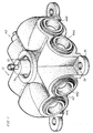
- Dispositif comprenant un collecteur (10, 10a) et un réservoir à air de véhicule automobile (12, 100) ayant un bouchon d'extrémité bombé (15) composé d'une ouverture (22) passant à travers celui-ci, le collecteur (10, 10a) étant fixé au bouchon d'extrémité bombé (15), et comprenant un corps (20, 20a) ayant à l'intérieur de celui-ci une ouverture centrale (25) servant d'orifice d'entrée vers et de sortie à partir de l'intérieur du réservoir, ledit corps ayant une pluralité de passages (44) qui s'ouvrent dans ladite ouverture centrale (25), ladite ouverture centrale étant définie par un bord annulaire (26, 126) qui s'étend dudit corps et est reçu à l'intérieur de ladite ouverture du bouchon d'extrémité (22) avec ledit bord annulaire s'étendant à travers ladite ouverture du bouchon d'extrémité à l'intérieur dudit réservoir (12, 100), chacun de ladite pluralité de passages (44) se terminant dans une surface terminale extérieure ouverte dudit corps (20, 20a), dans lequel l'un desdits passages (44) à l'extrémité extérieure de ce dernier présente un clapet de non-retour à voie unique qui y est fixé pour admettre l'air sous pression vers l'intérieur dudit réservoir via ledit passage, un autre desdits passages (44) à l'extrémité extérieure de celui-ci présente une soupape de sûreté (60) qui y est fixée et qui est sensible à la pression dans ledit réservoir et peut s'ouvrir lorsque ladite pression du réservoir dépasse une pression maximale prédéterminée, et au moins un passage supplémentaire (44) est prévu présentant un raccord recevant le tube à connecter (45) qui y est fixé afin de recevoir un tube à air flexible (50) via lequel un dispositif d'utilisation d'air comprimé à distance est raccordable audit réservoir.
- Dispositif selon la revendication 1, dans lequel ledit bord annulaire comprend un premier bord (26), un deuxième bord annulaire (28) étant prévu sur ledit corps (20) autour dudit premier bord (26) et définissant avec ledit premier bord un évidement annulaire de réception de joint torique (29), ledit deuxième bord annulaire présentant une surface terminale (28a) attenante à une surface exposée (27) dudit bouchon d'extrémité (15), ledit évidement de réception de joint torique contenant un joint torique (30) dans un engagement par pression avec ledit bouchon d'extrémité et scellant ledit corps audit réservoir (12).
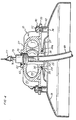
- Dispositif selon la revendication 2, dans lequel ledit réservoir (12) est composé de métal, le collecteur (10) comprenant, en outre, une pluralité de pieds de montage (35) sur ledit corps (20) s'étendant généralement radialement par rapport à ce dernier, lesdits pieds de montage étant supportés sur des plots d'appui (36) soudés à une surface extérieure dudit bouchon d'extrémité (15) qui supportent ledit collecteur sur ledit réservoir.
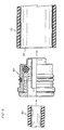
- Dispositif selon la revendication 1, dans lequel ledit réservoir d'air (100) est formé comme un composite, avec un rebord incorporant un raccord fileté polaire plastique ou métallique (105) audit bouchon d'extrémité bombé qui définit ladite ouverture du bouchon d'extrémité, le collecteur comprenant en outre une plaque de montage annulaire généralement radiale (110) montée sur ledit raccord fileté (105), le moyen de fixation (115) fixant ledit corps du collecteur (20a) à ladite plaque avec ledit bord annulaire (126) s'étendant dans ledit raccord (105) et l'ouverture du bouchon d'extrémité, un évidement annulaire de réception de joint torique formé dans une surface extérieure dudit bord annulaire, et un joint torique (128) reçu dans ledit évidement annulaire dans l'engagement par pression avec le rebord de manière interne dudit raccord (105) pour former un rideau d'air avec le rebord.
- Dispositif selon l'une quelconque des revendications précédentes, dans lequel le bord annulaire (26) s'étendant à partir dudit corps (20, 20a) dudit collecteur (10, 10a) via ladite ouverture du bouchon d'extrémité (22) forme une interface étanche à l'air non filetée avec ladite ouverture du bouchon d'extrémité (22).
- Dispositif selon l'une quelconque des revendications précédentes, comprenant une pluralité desdits passages (44), chacun présentant un raccord recevant le tube à connecter (45) dans ce dernier pour recevoir un tube à air flexible (50) par lequel un dispositif associé d'une pluralité de dispositifs d'utilisation d'air comprimé à distance est raccordable audit réservoir (12, 100).
- Dispositif selon l'une quelconque des revendications précédentes, comprenant une vanne de vidange normalement fermée que l'on peut actionner manuellement (75) fixée dans ladite ouverture centrale (25), ou dans l'un desdits passages (45) pour décharger l'eau accumulée dans ledit réservoir (12, 100) .
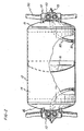
- Dispositif selon la revendication 7, comprenant un tuyau flexible (85) partant de ladite vanne de vidange (75) pour aller dans ledit intérieur du réservoir et présentant un orifice d'entrée (90) à l'extrémité éloignée de ce dernier positionné à un point bas gravitationnel dans ledit réservoir, de sorte que l'eau accumulée peut être enlevée dudit réservoir en ouvrant manuellement ladite vanne de vidange normalement fermée (75).
- Dispositif comprenant un collecteur (10, 10a) et un réservoir à air comprimé de véhicule automobile (12, 100) pour fournir de l'air sous pression à un système pneumatique de véhicule automobile et pour fournir un apport d'un tel air à une pluralité de dispositifs d'utilisation d'air comprimé, dans lequel le réservoir à pression présente un corps cylindrique (14) et un bouchon d'extrémité bombé (15) avec une ouverture (22) formée dans ledit bouchon d'extrémité, le collecteur (10, 100) comprenant un corps de collecteur (20, 20a), ledit corps présentant une ouverture centrale (25) s'étendant à travers ce dernier et servant d'orifice d'entrée vers et de sortie à partir de l'intérieur du réservoir, ledit corps étant monté sur ledit bouchon d'extrémité bombé (15) par rapport au scellement avec ladite ouverture centrale (25) dans un alignement général avec ladite ouverture du bouchon d'extrémité (22) et formant un scellement étanche à l'air entre ledit corps (20, 20a) et ladite ouverture du bouchon d'extrémité (22) autour de ladite ouverture du bouchon d'extrémité, ledit corps présentant, en outre, une pluralité de passages cylindriques s'étendant latéralement (44) présentant des extrémités intérieures s'ouvrant dans ladite ouverture centrale (25) et des extrémités extérieures éloignées, et chacun desdits passages (44) présentant une partie cylindrique allant vers l'intérieur à partir de ladite extrémité extérieure ouverte, dans lequel l'un desdits passages (44) à l'extrémité extérieure de ce dernier présente un clapet de non-retour à voie unique dans ce dernier pour admettre l'air sous pression vers l'intérieur dudit réservoir (12, 100) via ledit passage, et un autre desdits passages (44) à l'extrémité extérieure de ce dernier présente une soupape de sûreté (60) dans celui-ci et est sensible à la pression dans ledit réservoir et qui peut s'ouvrir lorsque ladite pression du réservoir dépasse une pression maximale prédéterminée, et les autres desdits passages (44) présentent des raccords recevant le tube à connecter (45) pour connecter les dispositifs d'utilisation d'air comprimé à distance audit réservoir, ladite ouverture centrale (25) ou l'un desdits passages (44) présentant dans ce dernier une vanne de vidange normalement fermée que l'on peut actionner manuellement (75), et un tuyau flexible (85) partant de ladite vanne de vidange pour aller dans ledit intérieur du réservoir et présentant un orifice d'entrée (90) à l'extrémité éloignée de ce dernier positionné à un point bas gravitationnel dans ledit réservoir, de sorte que l'eau accumulée peut être enlevée dudit réservoir en ouvrant manuellement ladite vanne de vidange normalement fermée (75).
- Dispositif selon la revendication 9, dans lequel ledit corps (20, 20a) dudit collecteur (10, 100) est monté sur ledit bouchon d'extrémité (15) dans un rapport de scellement non fileté à ladite ouverture du bouchon d'extrémité (22).
- Véhicule automobile, tel un camion, incorporant le dispositif selon l'une quelconque des revendications précédentes.
Applications Claiming Priority (3)
| Application Number | Priority Date | Filing Date | Title |
|---|---|---|---|
| US5257097P | 1997-07-15 | 1997-07-15 | |
| US52570P | 1997-07-15 | ||
| PCT/US1998/014557 WO1999004193A1 (fr) | 1997-07-15 | 1998-07-14 | Collecteur de reservoir d'air |
Publications (3)
| Publication Number | Publication Date |
|---|---|
| EP0925468A1 EP0925468A1 (fr) | 1999-06-30 |
| EP0925468A4 EP0925468A4 (fr) | 1999-09-01 |
| EP0925468B1 true EP0925468B1 (fr) | 2003-04-23 |
Family
ID=21978465
Family Applications (1)
| Application Number | Title | Priority Date | Filing Date |
|---|---|---|---|
| EP98934525A Expired - Lifetime EP0925468B1 (fr) | 1997-07-15 | 1998-07-14 | Arrangement comportant un reservoir d'air et un distributeur |
Country Status (5)
| Country | Link |
|---|---|
| US (1) | US6056007A (fr) |
| EP (1) | EP0925468B1 (fr) |
| AT (1) | ATE238514T1 (fr) |
| DE (1) | DE69813744D1 (fr) |
| WO (1) | WO1999004193A1 (fr) |
Families Citing this family (16)
| Publication number | Priority date | Publication date | Assignee | Title |
|---|---|---|---|---|
| US6971404B2 (en) * | 2002-03-20 | 2005-12-06 | G.T. Development Corporation | Pressure protection valve |
| US20030184150A1 (en) * | 2002-03-28 | 2003-10-02 | Legeza Thomas S. | Single check manifold |
| US6846162B2 (en) * | 2002-08-12 | 2005-01-25 | Wen San Chou | Cylinder housing for air compressor |
| US20060070722A1 (en) * | 2004-10-01 | 2006-04-06 | Shelton Jefferson L | Air cannon manifold |
| US20070209648A1 (en) * | 2006-03-10 | 2007-09-13 | Martin Engineering Company | Air cannon for removal of flowable material from a material handling system |
| US7837062B2 (en) | 2006-03-10 | 2010-11-23 | Martin Engineering Company | Air cannon for removal of flowable material from a material handling system |
| US20080236958A1 (en) * | 2007-03-29 | 2008-10-02 | Debiasi International Limited | Pressure vessel for vehicular air brake system |
| AT10161U1 (de) * | 2007-05-10 | 2008-10-15 | Alutech Gmbh | Druckbehälter zur montage an einem fahrzeug |
| US20110108144A1 (en) * | 2009-11-09 | 2011-05-12 | Anova Resources LLC | Multi-port quick connect fluid treatment tank head |
| US9255647B2 (en) * | 2013-02-26 | 2016-02-09 | Halliburton Energy Services, Inc. | Dynamic fluid gas bleeder manifold |
| US10436386B2 (en) | 2016-09-02 | 2019-10-08 | AccuAir Control Systems, LLC | Systems, devices and methods for modular pressure vessels |
| US11054074B2 (en) | 2016-09-21 | 2021-07-06 | Arnott, Llc | System and method for push-to-connect couplings with integrated filtration |
| WO2019084195A1 (fr) | 2017-10-27 | 2019-05-02 | AccuAir Control Systems, LLC | Système d'isolation de vibrations |
| CN112124284B (zh) * | 2020-09-29 | 2022-06-24 | 东风商用车有限公司 | 复合材料贮气筒 |
| CN112706739A (zh) * | 2021-01-25 | 2021-04-27 | 一汽解放汽车有限公司 | 贮气筒、制动系统和车辆 |
| WO2022174304A1 (fr) * | 2021-02-19 | 2022-08-25 | Stewart Thompson | Dispositif pour recevoir un fluide sous pression |
Citations (1)
| Publication number | Priority date | Publication date | Assignee | Title |
|---|---|---|---|---|
| WO1998058206A1 (fr) * | 1997-06-18 | 1998-12-23 | Erwin Weh | Raccordement de remplissage destine a une valve de bouteille de gaz |
Family Cites Families (16)
| Publication number | Priority date | Publication date | Assignee | Title |
|---|---|---|---|---|
| US554458A (en) * | 1896-02-11 | Racking apparatus | ||
| US566024A (en) * | 1896-08-18 | Oil-torch | ||
| US1683021A (en) * | 1927-09-03 | 1928-09-04 | George A Brown | Oil-dispensing apparatus |
| US2121511A (en) * | 1934-12-02 | 1938-06-21 | Fur Holzveredlung Ag | Closure for barrels and the like |
| US3462041A (en) * | 1968-09-13 | 1969-08-19 | Gen Dynamics Corp | High pressure sealing structure |
| US3650551A (en) * | 1971-02-08 | 1972-03-21 | Borg Warner | Self-sealing tank connector |
| US3854526A (en) * | 1973-05-31 | 1974-12-17 | Royal Industries | Tank |
| US4139020A (en) * | 1977-04-04 | 1979-02-13 | The Bendix Corporation | Modular dash control valve manifold |
| US4334561A (en) * | 1979-01-03 | 1982-06-15 | Valico P.V.B.A. | Head piece for a tank for liquefied gas |
| US4564246A (en) * | 1983-11-14 | 1986-01-14 | Sloan Valve Company | Combined reservoir and pipe hanger for railroad brakes |
| US4699292A (en) * | 1986-08-20 | 1987-10-13 | Westvaco Corporation | Pulp bleaching tower pressure relief hatch |
| US5230539A (en) * | 1991-12-31 | 1993-07-27 | Dana Corporation | Quick connect tube coupling |
| US5287987A (en) * | 1992-08-31 | 1994-02-22 | Comdyne I, Inc. | Filament wound pressure vessel |
| US5236250A (en) * | 1992-09-02 | 1993-08-17 | Midland Brake, Inc. | Full-function valve for heavy duty semi-trailer brake systems |
| US5709252A (en) * | 1995-06-06 | 1998-01-20 | Progas, Inc. | Natural gas distribution system |
| AUPO437096A0 (en) * | 1996-12-23 | 1997-01-23 | Stm Auto Gas Tanks Pty Ltd | Integrated filling, dispensing and contents indication unit for liquefied gas tank |
-
1998
- 1998-07-13 US US09/114,536 patent/US6056007A/en not_active Expired - Fee Related
- 1998-07-14 DE DE69813744T patent/DE69813744D1/de not_active Expired - Lifetime
- 1998-07-14 WO PCT/US1998/014557 patent/WO1999004193A1/fr active IP Right Grant
- 1998-07-14 EP EP98934525A patent/EP0925468B1/fr not_active Expired - Lifetime
- 1998-07-14 AT AT98934525T patent/ATE238514T1/de not_active IP Right Cessation
Patent Citations (1)
| Publication number | Priority date | Publication date | Assignee | Title |
|---|---|---|---|---|
| WO1998058206A1 (fr) * | 1997-06-18 | 1998-12-23 | Erwin Weh | Raccordement de remplissage destine a une valve de bouteille de gaz |
Also Published As
| Publication number | Publication date |
|---|---|
| EP0925468A1 (fr) | 1999-06-30 |
| WO1999004193A1 (fr) | 1999-01-28 |
| EP0925468A4 (fr) | 1999-09-01 |
| DE69813744D1 (de) | 2003-05-28 |
| US6056007A (en) | 2000-05-02 |
| ATE238514T1 (de) | 2003-05-15 |
Similar Documents
| Publication | Publication Date | Title |
|---|---|---|
| EP0925468B1 (fr) | Arrangement comportant un reservoir d'air et un distributeur | |
| US8960484B2 (en) | Transport tank | |
| US5429167A (en) | Universal central tire inflation system for trailers | |
| EP1325829B1 (fr) | Contrôle de ventilation des vapeurs de carburant d'un réservoir de carburant | |
| US6260595B1 (en) | Unitized hub cap | |
| US4637435A (en) | Antiseal arrangement for hydropneumatic pressure tanks | |
| US20180304699A1 (en) | Tire pressure management system | |
| EP0679811B1 (fr) | Diffuseur et serrage d'un réservoir d'air pour un accumulateur hydropneumatique | |
| MXPA04007571A (es) | Modulo de sistema de aire que incluye deposito y estructura de montaje. | |
| US4487446A (en) | Combined bumper and air storage system | |
| US6247763B1 (en) | Pressure fluid reservoir for a vehicle hydraulic brake system | |
| CA2495054A1 (fr) | Dessiccateur d'air a membrane et procede d'installation de ce dessiccateur dans un vehicule | |
| US6422013B2 (en) | Fluid reservoir system for a master cylinder | |
| US4489556A (en) | Tandem brake master cylinder | |
| CA1242476A (fr) | Reservoir avec support de tuyauterie combine pour freins de vehicule ferroviaire | |
| US6786560B2 (en) | Integrated air dryer module for vehicle air brake | |
| US6119735A (en) | Filling of tanks with volatile liquids | |
| US20030146661A1 (en) | Pressure protection manifold | |
| US4502281A (en) | Fluid reservoir | |
| WO2000034092A2 (fr) | Cartouche de raccordement pour reservoirs d'air | |
| US4217972A (en) | Non-metallic hydraulic lift casing | |
| CN220785731U (zh) | 储气筒和具有其的车辆 | |
| CN116968711B (zh) | 一种车载储罐及其制造方法 | |
| AU710621B2 (en) | Dual chamber fluid storage vessel | |
| US6050307A (en) | Method and apparatus for removing a heavier liquid from a container having multiple liquids |
Legal Events
| Date | Code | Title | Description |
|---|---|---|---|
| PUAI | Public reference made under article 153(3) epc to a published international application that has entered the european phase |
Free format text: ORIGINAL CODE: 0009012 |
|
| AK | Designated contracting states |
Kind code of ref document: A1 Designated state(s): AT DE FR GB SE |
|
| A4 | Supplementary search report drawn up and despatched |
Effective date: 19990720 |
|
| AK | Designated contracting states |
Kind code of ref document: A4 Designated state(s): AT DE FR GB SE |
|
| RIC1 | Information provided on ipc code assigned before grant |
Free format text: 6F 16L 43/00 A, 6F 17C 13/04 B |
|
| 17P | Request for examination filed |
Effective date: 19990723 |
|
| 17Q | First examination report despatched |
Effective date: 20011126 |
|
| RTI1 | Title (correction) |
Free format text: AIR TANK AND MANIFOLD ARRANGEMENT |
|
| GRAH | Despatch of communication of intention to grant a patent |
Free format text: ORIGINAL CODE: EPIDOS IGRA |
|
| RTI1 | Title (correction) |
Free format text: AIR TANK AND MANIFOLD ARRANGEMENT |
|
| GRAH | Despatch of communication of intention to grant a patent |
Free format text: ORIGINAL CODE: EPIDOS IGRA |
|
| GRAA | (expected) grant |
Free format text: ORIGINAL CODE: 0009210 |
|
| AK | Designated contracting states |
Designated state(s): AT DE FR GB SE |
|
| PG25 | Lapsed in a contracting state [announced via postgrant information from national office to epo] |
Ref country code: FR Free format text: LAPSE BECAUSE OF FAILURE TO SUBMIT A TRANSLATION OF THE DESCRIPTION OR TO PAY THE FEE WITHIN THE PRESCRIBED TIME-LIMIT Effective date: 20030423 Ref country code: AT Free format text: LAPSE BECAUSE OF FAILURE TO SUBMIT A TRANSLATION OF THE DESCRIPTION OR TO PAY THE FEE WITHIN THE PRESCRIBED TIME-LIMIT Effective date: 20030423 |
|
| REG | Reference to a national code |
Ref country code: GB Ref legal event code: FG4D |
|
| REF | Corresponds to: |
Ref document number: 69813744 Country of ref document: DE Date of ref document: 20030528 Kind code of ref document: P |
|
| PG25 | Lapsed in a contracting state [announced via postgrant information from national office to epo] |
Ref country code: SE Free format text: LAPSE BECAUSE OF FAILURE TO SUBMIT A TRANSLATION OF THE DESCRIPTION OR TO PAY THE FEE WITHIN THE PRESCRIBED TIME-LIMIT Effective date: 20030723 Ref country code: GB Free format text: LAPSE BECAUSE OF NON-PAYMENT OF DUE FEES Effective date: 20030723 |
|
| PG25 | Lapsed in a contracting state [announced via postgrant information from national office to epo] |
Ref country code: DE Free format text: LAPSE BECAUSE OF FAILURE TO SUBMIT A TRANSLATION OF THE DESCRIPTION OR TO PAY THE FEE WITHIN THE PRESCRIBED TIME-LIMIT Effective date: 20030724 |
|
| PLBE | No opposition filed within time limit |
Free format text: ORIGINAL CODE: 0009261 |
|
| STAA | Information on the status of an ep patent application or granted ep patent |
Free format text: STATUS: NO OPPOSITION FILED WITHIN TIME LIMIT |
|
| GBPC | Gb: european patent ceased through non-payment of renewal fee |
Effective date: 20030723 |
|
| 26N | No opposition filed |
Effective date: 20040126 |
|
| EN | Fr: translation not filed |