EP0925468B1 - Air tank and manifold arrangement - Google Patents
Air tank and manifold arrangement Download PDFInfo
- Publication number
- EP0925468B1 EP0925468B1 EP98934525A EP98934525A EP0925468B1 EP 0925468 B1 EP0925468 B1 EP 0925468B1 EP 98934525 A EP98934525 A EP 98934525A EP 98934525 A EP98934525 A EP 98934525A EP 0925468 B1 EP0925468 B1 EP 0925468B1
- Authority
- EP
- European Patent Office
- Prior art keywords
- tank
- end cap
- opening
- manifold
- pressure
- Prior art date
- Legal status (The legal status is an assumption and is not a legal conclusion. Google has not performed a legal analysis and makes no representation as to the accuracy of the status listed.)
- Expired - Lifetime
Links
Images


Classifications
-
- B—PERFORMING OPERATIONS; TRANSPORTING
- B60—VEHICLES IN GENERAL
- B60T—VEHICLE BRAKE CONTROL SYSTEMS OR PARTS THEREOF; BRAKE CONTROL SYSTEMS OR PARTS THEREOF, IN GENERAL; ARRANGEMENT OF BRAKING ELEMENTS ON VEHICLES IN GENERAL; PORTABLE DEVICES FOR PREVENTING UNWANTED MOVEMENT OF VEHICLES; VEHICLE MODIFICATIONS TO FACILITATE COOLING OF BRAKES
- B60T17/00—Component parts, details, or accessories of power brake systems not covered by groups B60T8/00, B60T13/00 or B60T15/00, or presenting other characteristic features
- B60T17/04—Arrangements of piping, valves in the piping, e.g. cut-off valves, couplings or air hoses
- B60T17/043—Brake line couplings, air hoses and stopcocks
-
- B—PERFORMING OPERATIONS; TRANSPORTING
- B60—VEHICLES IN GENERAL
- B60T—VEHICLE BRAKE CONTROL SYSTEMS OR PARTS THEREOF; BRAKE CONTROL SYSTEMS OR PARTS THEREOF, IN GENERAL; ARRANGEMENT OF BRAKING ELEMENTS ON VEHICLES IN GENERAL; PORTABLE DEVICES FOR PREVENTING UNWANTED MOVEMENT OF VEHICLES; VEHICLE MODIFICATIONS TO FACILITATE COOLING OF BRAKES
- B60T17/00—Component parts, details, or accessories of power brake systems not covered by groups B60T8/00, B60T13/00 or B60T15/00, or presenting other characteristic features
- B60T17/04—Arrangements of piping, valves in the piping, e.g. cut-off valves, couplings or air hoses
-
- B—PERFORMING OPERATIONS; TRANSPORTING
- B60—VEHICLES IN GENERAL
- B60T—VEHICLE BRAKE CONTROL SYSTEMS OR PARTS THEREOF; BRAKE CONTROL SYSTEMS OR PARTS THEREOF, IN GENERAL; ARRANGEMENT OF BRAKING ELEMENTS ON VEHICLES IN GENERAL; PORTABLE DEVICES FOR PREVENTING UNWANTED MOVEMENT OF VEHICLES; VEHICLE MODIFICATIONS TO FACILITATE COOLING OF BRAKES
- B60T17/00—Component parts, details, or accessories of power brake systems not covered by groups B60T8/00, B60T13/00 or B60T15/00, or presenting other characteristic features
- B60T17/06—Applications or arrangements of reservoirs
-
- F—MECHANICAL ENGINEERING; LIGHTING; HEATING; WEAPONS; BLASTING
- F17—STORING OR DISTRIBUTING GASES OR LIQUIDS
- F17C—VESSELS FOR CONTAINING OR STORING COMPRESSED, LIQUEFIED OR SOLIDIFIED GASES; FIXED-CAPACITY GAS-HOLDERS; FILLING VESSELS WITH, OR DISCHARGING FROM VESSELS, COMPRESSED, LIQUEFIED, OR SOLIDIFIED GASES
- F17C13/00—Details of vessels or of the filling or discharging of vessels
- F17C13/04—Arrangement or mounting of valves
-
- F—MECHANICAL ENGINEERING; LIGHTING; HEATING; WEAPONS; BLASTING
- F17—STORING OR DISTRIBUTING GASES OR LIQUIDS
- F17C—VESSELS FOR CONTAINING OR STORING COMPRESSED, LIQUEFIED OR SOLIDIFIED GASES; FIXED-CAPACITY GAS-HOLDERS; FILLING VESSELS WITH, OR DISCHARGING FROM VESSELS, COMPRESSED, LIQUEFIED, OR SOLIDIFIED GASES
- F17C2201/00—Vessel construction, in particular geometry, arrangement or size
- F17C2201/01—Shape
- F17C2201/0104—Shape cylindrical
- F17C2201/0109—Shape cylindrical with exteriorly curved end-piece
-
- F—MECHANICAL ENGINEERING; LIGHTING; HEATING; WEAPONS; BLASTING
- F17—STORING OR DISTRIBUTING GASES OR LIQUIDS
- F17C—VESSELS FOR CONTAINING OR STORING COMPRESSED, LIQUEFIED OR SOLIDIFIED GASES; FIXED-CAPACITY GAS-HOLDERS; FILLING VESSELS WITH, OR DISCHARGING FROM VESSELS, COMPRESSED, LIQUEFIED, OR SOLIDIFIED GASES
- F17C2201/00—Vessel construction, in particular geometry, arrangement or size
- F17C2201/01—Shape
- F17C2201/0147—Shape complex
- F17C2201/0166—Shape complex divided in several chambers
-
- F—MECHANICAL ENGINEERING; LIGHTING; HEATING; WEAPONS; BLASTING
- F17—STORING OR DISTRIBUTING GASES OR LIQUIDS
- F17C—VESSELS FOR CONTAINING OR STORING COMPRESSED, LIQUEFIED OR SOLIDIFIED GASES; FIXED-CAPACITY GAS-HOLDERS; FILLING VESSELS WITH, OR DISCHARGING FROM VESSELS, COMPRESSED, LIQUEFIED, OR SOLIDIFIED GASES
- F17C2201/00—Vessel construction, in particular geometry, arrangement or size
- F17C2201/03—Orientation
- F17C2201/035—Orientation with substantially horizontal main axis
-
- F—MECHANICAL ENGINEERING; LIGHTING; HEATING; WEAPONS; BLASTING
- F17—STORING OR DISTRIBUTING GASES OR LIQUIDS
- F17C—VESSELS FOR CONTAINING OR STORING COMPRESSED, LIQUEFIED OR SOLIDIFIED GASES; FIXED-CAPACITY GAS-HOLDERS; FILLING VESSELS WITH, OR DISCHARGING FROM VESSELS, COMPRESSED, LIQUEFIED, OR SOLIDIFIED GASES
- F17C2201/00—Vessel construction, in particular geometry, arrangement or size
- F17C2201/05—Size
- F17C2201/056—Small (<1 m3)
-
- F—MECHANICAL ENGINEERING; LIGHTING; HEATING; WEAPONS; BLASTING
- F17—STORING OR DISTRIBUTING GASES OR LIQUIDS
- F17C—VESSELS FOR CONTAINING OR STORING COMPRESSED, LIQUEFIED OR SOLIDIFIED GASES; FIXED-CAPACITY GAS-HOLDERS; FILLING VESSELS WITH, OR DISCHARGING FROM VESSELS, COMPRESSED, LIQUEFIED, OR SOLIDIFIED GASES
- F17C2205/00—Vessel construction, in particular mounting arrangements, attachments or identifications means
- F17C2205/01—Mounting arrangements
- F17C2205/0123—Mounting arrangements characterised by number of vessels
- F17C2205/013—Two or more vessels
- F17C2205/0134—Two or more vessels characterised by the presence of fluid connection between vessels
- F17C2205/0146—Two or more vessels characterised by the presence of fluid connection between vessels with details of the manifold
-
- F—MECHANICAL ENGINEERING; LIGHTING; HEATING; WEAPONS; BLASTING
- F17—STORING OR DISTRIBUTING GASES OR LIQUIDS
- F17C—VESSELS FOR CONTAINING OR STORING COMPRESSED, LIQUEFIED OR SOLIDIFIED GASES; FIXED-CAPACITY GAS-HOLDERS; FILLING VESSELS WITH, OR DISCHARGING FROM VESSELS, COMPRESSED, LIQUEFIED, OR SOLIDIFIED GASES
- F17C2205/00—Vessel construction, in particular mounting arrangements, attachments or identifications means
- F17C2205/03—Fluid connections, filters, valves, closure means or other attachments
- F17C2205/0302—Fittings, valves, filters, or components in connection with the gas storage device
- F17C2205/0323—Valves
- F17C2205/0332—Safety valves or pressure relief valves
-
- F—MECHANICAL ENGINEERING; LIGHTING; HEATING; WEAPONS; BLASTING
- F17—STORING OR DISTRIBUTING GASES OR LIQUIDS
- F17C—VESSELS FOR CONTAINING OR STORING COMPRESSED, LIQUEFIED OR SOLIDIFIED GASES; FIXED-CAPACITY GAS-HOLDERS; FILLING VESSELS WITH, OR DISCHARGING FROM VESSELS, COMPRESSED, LIQUEFIED, OR SOLIDIFIED GASES
- F17C2205/00—Vessel construction, in particular mounting arrangements, attachments or identifications means
- F17C2205/03—Fluid connections, filters, valves, closure means or other attachments
- F17C2205/0302—Fittings, valves, filters, or components in connection with the gas storage device
- F17C2205/0323—Valves
- F17C2205/0335—Check-valves or non-return valves
-
- F—MECHANICAL ENGINEERING; LIGHTING; HEATING; WEAPONS; BLASTING
- F17—STORING OR DISTRIBUTING GASES OR LIQUIDS
- F17C—VESSELS FOR CONTAINING OR STORING COMPRESSED, LIQUEFIED OR SOLIDIFIED GASES; FIXED-CAPACITY GAS-HOLDERS; FILLING VESSELS WITH, OR DISCHARGING FROM VESSELS, COMPRESSED, LIQUEFIED, OR SOLIDIFIED GASES
- F17C2205/00—Vessel construction, in particular mounting arrangements, attachments or identifications means
- F17C2205/03—Fluid connections, filters, valves, closure means or other attachments
- F17C2205/0388—Arrangement of valves, regulators, filters
- F17C2205/0394—Arrangement of valves, regulators, filters in direct contact with the pressure vessel
- F17C2205/0397—Arrangement of valves, regulators, filters in direct contact with the pressure vessel on both sides of the pressure vessel
-
- F—MECHANICAL ENGINEERING; LIGHTING; HEATING; WEAPONS; BLASTING
- F17—STORING OR DISTRIBUTING GASES OR LIQUIDS
- F17C—VESSELS FOR CONTAINING OR STORING COMPRESSED, LIQUEFIED OR SOLIDIFIED GASES; FIXED-CAPACITY GAS-HOLDERS; FILLING VESSELS WITH, OR DISCHARGING FROM VESSELS, COMPRESSED, LIQUEFIED, OR SOLIDIFIED GASES
- F17C2221/00—Handled fluid, in particular type of fluid
- F17C2221/03—Mixtures
- F17C2221/031—Air
-
- F—MECHANICAL ENGINEERING; LIGHTING; HEATING; WEAPONS; BLASTING
- F17—STORING OR DISTRIBUTING GASES OR LIQUIDS
- F17C—VESSELS FOR CONTAINING OR STORING COMPRESSED, LIQUEFIED OR SOLIDIFIED GASES; FIXED-CAPACITY GAS-HOLDERS; FILLING VESSELS WITH, OR DISCHARGING FROM VESSELS, COMPRESSED, LIQUEFIED, OR SOLIDIFIED GASES
- F17C2223/00—Handled fluid before transfer, i.e. state of fluid when stored in the vessel or before transfer from the vessel
- F17C2223/01—Handled fluid before transfer, i.e. state of fluid when stored in the vessel or before transfer from the vessel characterised by the phase
- F17C2223/0107—Single phase
- F17C2223/0123—Single phase gaseous, e.g. CNG, GNC
-
- F—MECHANICAL ENGINEERING; LIGHTING; HEATING; WEAPONS; BLASTING
- F17—STORING OR DISTRIBUTING GASES OR LIQUIDS
- F17C—VESSELS FOR CONTAINING OR STORING COMPRESSED, LIQUEFIED OR SOLIDIFIED GASES; FIXED-CAPACITY GAS-HOLDERS; FILLING VESSELS WITH, OR DISCHARGING FROM VESSELS, COMPRESSED, LIQUEFIED, OR SOLIDIFIED GASES
- F17C2223/00—Handled fluid before transfer, i.e. state of fluid when stored in the vessel or before transfer from the vessel
- F17C2223/04—Handled fluid before transfer, i.e. state of fluid when stored in the vessel or before transfer from the vessel characterised by other properties of handled fluid before transfer
- F17C2223/042—Localisation of the removal point
- F17C2223/046—Localisation of the removal point in the liquid
- F17C2223/047—Localisation of the removal point in the liquid with a dip tube
-
- F—MECHANICAL ENGINEERING; LIGHTING; HEATING; WEAPONS; BLASTING
- F17—STORING OR DISTRIBUTING GASES OR LIQUIDS
- F17C—VESSELS FOR CONTAINING OR STORING COMPRESSED, LIQUEFIED OR SOLIDIFIED GASES; FIXED-CAPACITY GAS-HOLDERS; FILLING VESSELS WITH, OR DISCHARGING FROM VESSELS, COMPRESSED, LIQUEFIED, OR SOLIDIFIED GASES
- F17C2260/00—Purposes of gas storage and gas handling
- F17C2260/03—Dealing with losses
- F17C2260/035—Dealing with losses of fluid
- F17C2260/036—Avoiding leaks
-
- F—MECHANICAL ENGINEERING; LIGHTING; HEATING; WEAPONS; BLASTING
- F17—STORING OR DISTRIBUTING GASES OR LIQUIDS
- F17C—VESSELS FOR CONTAINING OR STORING COMPRESSED, LIQUEFIED OR SOLIDIFIED GASES; FIXED-CAPACITY GAS-HOLDERS; FILLING VESSELS WITH, OR DISCHARGING FROM VESSELS, COMPRESSED, LIQUEFIED, OR SOLIDIFIED GASES
- F17C2270/00—Applications
- F17C2270/01—Applications for fluid transport or storage
- F17C2270/0165—Applications for fluid transport or storage on the road
- F17C2270/0168—Applications for fluid transport or storage on the road by vehicles
- F17C2270/0171—Trucks
-
- Y—GENERAL TAGGING OF NEW TECHNOLOGICAL DEVELOPMENTS; GENERAL TAGGING OF CROSS-SECTIONAL TECHNOLOGIES SPANNING OVER SEVERAL SECTIONS OF THE IPC; TECHNICAL SUBJECTS COVERED BY FORMER USPC CROSS-REFERENCE ART COLLECTIONS [XRACs] AND DIGESTS
- Y10—TECHNICAL SUBJECTS COVERED BY FORMER USPC
- Y10T—TECHNICAL SUBJECTS COVERED BY FORMER US CLASSIFICATION
- Y10T137/00—Fluid handling
- Y10T137/6851—With casing, support, protector or static constructional installations
- Y10T137/6855—Vehicle
- Y10T137/6881—Automotive
-
- Y—GENERAL TAGGING OF NEW TECHNOLOGICAL DEVELOPMENTS; GENERAL TAGGING OF CROSS-SECTIONAL TECHNOLOGIES SPANNING OVER SEVERAL SECTIONS OF THE IPC; TECHNICAL SUBJECTS COVERED BY FORMER USPC CROSS-REFERENCE ART COLLECTIONS [XRACs] AND DIGESTS
- Y10—TECHNICAL SUBJECTS COVERED BY FORMER USPC
- Y10T—TECHNICAL SUBJECTS COVERED BY FORMER US CLASSIFICATION
- Y10T137/00—Fluid handling
- Y10T137/8593—Systems
- Y10T137/85938—Non-valved flow dividers
-
- Y—GENERAL TAGGING OF NEW TECHNOLOGICAL DEVELOPMENTS; GENERAL TAGGING OF CROSS-SECTIONAL TECHNOLOGIES SPANNING OVER SEVERAL SECTIONS OF THE IPC; TECHNICAL SUBJECTS COVERED BY FORMER USPC CROSS-REFERENCE ART COLLECTIONS [XRACs] AND DIGESTS
- Y10—TECHNICAL SUBJECTS COVERED BY FORMER USPC
- Y10T—TECHNICAL SUBJECTS COVERED BY FORMER US CLASSIFICATION
- Y10T137/00—Fluid handling
- Y10T137/8593—Systems
- Y10T137/86292—System with plural openings, one a gas vent or access opening
- Y10T137/86324—Tank with gas vent and inlet or outlet
- Y10T137/86332—Vent and inlet or outlet in unitary mounting
-
- Y—GENERAL TAGGING OF NEW TECHNOLOGICAL DEVELOPMENTS; GENERAL TAGGING OF CROSS-SECTIONAL TECHNOLOGIES SPANNING OVER SEVERAL SECTIONS OF THE IPC; TECHNICAL SUBJECTS COVERED BY FORMER USPC CROSS-REFERENCE ART COLLECTIONS [XRACs] AND DIGESTS
- Y10—TECHNICAL SUBJECTS COVERED BY FORMER USPC
- Y10T—TECHNICAL SUBJECTS COVERED BY FORMER US CLASSIFICATION
- Y10T137/00—Fluid handling
- Y10T137/8593—Systems
- Y10T137/86348—Tank with internally extending flow guide, pipe or conduit
Definitions
- This invention relates to multiple port manifolds for air tanks, such as an air storage tank for supplying air to the air-pressure operated or supplying components of a truck or semi-trailer, such as to an air compressor or to the air brakes.
- welded bushings have been used, one for each pneumatic line which is extended from the tank, one for the tank inlet, to incorporate a check valve, and still another to incorporate a drain valve to permit condensed water to be drained from the tank, and perhaps another to receive a high pressure release valve.
- the tank closest to the air compressor is known as a "wet" tank since it receives condensed moisture in the line from the pump.
- Such wet tanks have thus been required to have some means for draining out the condensed moisture in the form of a bushing-mounted valve, commonly located at the bottom of the tank.
- Lightweight composite air pressure tanks are beginning to replace the traditional metal tanks in truck and semi-trailer operations and the like. Such composite tanks do not lend themselves to conventional attachments such as bushings as have been used in the past in connection with metal tanks. There is accordingly a need for an air tank manifold particularly adapted for use with composite tanks.
- a manifold and air reservoir tank arrangement as defined in claim 1.
- the multiple-port manifolds are designed to be used on metal tanks, such as steel or aluminum, or on composite-wound air tanks, such as reservoirs for heavy duty air systems for truck air brakes and the like.
- the common maximum working pressure for such reservoirs is 103.4x10 4 Pa (150 PSI gauge).
- the multiple-port manifolds are designed both as a distributor of air lines and as a housing for valves which are typically found in truck air brake reservoirs, including one way check valves, pressure protection valves, drain valves, pressure relief valves, and the like.
- air tank connection locations are found anywhere on the body of the tank or at either end of the tank.
- the manifold arrangement embodying this invention allows all of the air lines to be routed to one location, which provides an assistance in standardizing air harnesses and reducing costs.
- the manifolds are designed to employ push-to-connect fittings, thereby eliminating the now-used NPT-type thread with compression fittings, that are labor intensive and prone to leakage.
- a particularly advantageous composite tank for air pressure sources on motor vehicles are the like is that shown in Gaiser US-A-5,287,987 issued February 22, 1994.
- a multi-function manifold is mounted on a domed or head end of an air pressure reservoir in a vehicle air brake system by which a supply of air under pressure is provided to a plurality of air pressure utilization devices.
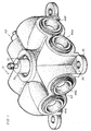
- the manifold has a body that forms a plurality of laterally-extending cylindrical passageways, with inner ends opening into a central common opening or passage and outer ends or ports that receive push-to-connect fittings therein by which air hoses may be attached to the tank at a common location.
- the manifold may have eight connections arranged in four orthogonally-related pairs of side-by-side located ports leading into the central common, passage or opening.
- a particular advantage of the manifolds of arrangements embodying this invention is that the number of tank connections through the tank wall is reduced to one, and the problem of leakage or proper fitting is substantially reduced.
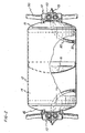
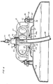
- a manifold is shown generally at 10. As shown in Figs. 2 and 3, the manifold 10 is mounted on a domed end cap of a metal cylindrical air reservoir tank.
- a dual-chamber metal tank 12 is shown with a cylindrical body or shell 14 and opposed closing domed end caps 15.
- the tank 12 is a dual compartment tank having an internal partition 16 which, effectively, divides the tank 12 into two separate reservoir sections.
- the manifold 10 is formed with a generally four-sided housing or body 20 that is adapted to be mounted over a central common inlet and outlet hole or opening 22 formed in the wall 27 of the associated domed end cap 15.
- the body 20 has a central common inlet and outlet passage or opening 25 that is open into the interior of the tank and positioned axially of the tank.
- the central opening 25 is defined by a first annular lip 26 that is proportioned to extend through the tank opening 22, through the wall 27, into the interior of the tank by a short distance.
- the body 20 further forms a second annular lip 28 that is positioned in surrounding relation to the first annular lip 26 and which has a terminal surface 20a adapted to abut the exposed outer surface of the end cap wall 27 when the body 20 is mounted thereon. Also, the lip 28 forms with the lip 26 an annular O-ring receiving recess 29 within which an O-ring 30 is received and is compressed in the space against the adjacent surface of the wall 27 and thereby is in pressure engagement with the end cap 15, for sealing the body 20 to the tank 12.
- the body 20 is supported on the end cap by a plurality of mounting feet 35 that extend generally radially of the tank axis and of the central opening 25, at each of four corners of the body 20 as shown in Fig. 3.
- the feet 35 are proportioned to be supported and mounted on individual studs 35 which in the case of a metal tank are welded to the outer surface of the end cap wall 27 in the appropriate location, and a threaded upper portion 37 of the stud extends through an opening 38 formed in the feet 35 and accepts a retaining nut 40.
- the studs 36 are welded in place by a drawn arc stud welding machine, as well known in the art.
- Tubular spacers 42 are positioned over the studs 36 as supports for the feet 35 of the body 20.
- the body 20 is fixably mounted on an end cap with the O-ring seal 30 partially compressed within the O-ring receiving recess or groove 29, and with the first annular lip 26 extending through the end cap opening 22 and forming a close mechanical fit thereto. It will thus be apparent that a non-threaded airtight seal is formed between the annular lip 26 and end cap opening 22.
- the body 20 is formed with a plurality of cylindrical passages that intersect the central opening 25 and which extend transversely outwardly from the axis of the central opening 25 in an orthogonal arrangement.
- eight such passages are formed in parallel pairs of two, as shown in Figs. 1 and 2, so that each passage is in at least partial intersecting relation to the central opening 25 within the body 20. Therefore, the body 20 of the manifold 10 is formed with a pair of passages 44a and 44b that are in orthogonal relation to a second pair of passages 44c and 44d. Similar passages 44e, f, and 44g, h are located, in pairs, on the remaining two sides of the manifold 10. Each passage is identical in construction and is adapted to contain a push-to-connect connector for accepting therein a flexible air line or tube, such as the air line 50 shown in Fig. 2.
- Each of the passages 44 may define either an inlet or outlet port that is connected in common with the remaining passages 44 by the manifold to the central opening 25. While several of the ports defined by the passages 44 may be used for different purposes, at least a plurality are provided with fittings comprising push-to-connect internal couplings 45 adapted to receive, support and grip associated flexible air lines 50, as shown in Fig. 5. Such an internal coupling may be made in accordance with the teachings of US-A-5,230,539 issued July 27, 1993, and offered by the Dana Corporation as part number 117-02200-TAB, of 4675 Clark Road, Sarasota, Florida 34233.
- one of the passages 44 may instead receive a fitting comprising a high pressure safety relief valve such as the relief valve part number 410-150 made by GT Development Corporation, of 6437 South 44 th Street, Tuckwila, Washington 98168 and identified by the reference numeral 60 in Fig. 3, which is openable when the pressure in the tank exceeds a predetermined maximum pressure.
- the pressure relief fitting and similar items that may require service are retained by a snap ring, such as the snap ring 62 retaining the drain valve 75 in Fig. 4, as described below.
- the remaining items that are installed in the passages 44 of the body 20 may be installed permanently using a press fit, as necessary.
- the central passage or opening 25 of the manifold 10 is extended through the top 27 of the body and forms an additional upwardly-facing.
- central opening 70 internally configured the same as the passages 44.
- the open outer end of each of the passages 44 is configured identically to the open end of the opening 70 by which an insert may be received, and retained by the snap ring 62 and sealed by an O-ring 63.
- the opening 70 is particularly used to receive therein the water drain valve 75.
- the water drain valve may have a valve pintle 76 which is operated by a pull rope 77 from a remote location, to open the normally closed valve, and the valve 75 may be part number 4102-1 of GT Development Corporation, previously identified.
- An inlet stem 80 on the valve 75 receives a flexible water drain tube 85 that extends into the tank interior with an inlet end 90 (Fig. 2) resting on the tank bottom.
- the inlet end is weighted so that it assumes a position at the lowest part of the tank, and when the valve 75 is opened by pulling on the pintle 76, any water that has collected at the lowest point of the valve will be expelled by the internal air pressure through the tube 85 and out of the valve 75.
- drain valve 75 in the central passage of opening 25 it could alternatively be placed in one of the other passages, such as one of the passages 44, as all of the passages 44, and the opening 70, are formed to the same dimensions and configuration for the purpose of interchangeably retaining the particular fittings as may be desired.
- one of the passages 4 may receive a one-way check valve therein by means of which air under pressure may be applied to the interior of the tank and then retained under pressure.
- a check valve may be part number SK-J2058 of Q 3 JMC, Inc., of 777 Manor Park Drive, Columbus, Ohio 43228.
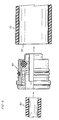
- Fig. 6 represents a modified form of the manifold 10a fitted on the end of a filament wound pressure tank, such as the pressure tank described in the Gaiser US patent '987, identified above. Where possible, like reference numerals have been used to identify like components of the manifold 10a.
- the domed end of a composite filament would reinforced tank 100 is provided with a neck incorporating an integrated metal (or plastic) polar fitting 105.
- the polar fitting 105 is integrally attached to and forms part of the tank 100.
- a portion of the air impervious PET (polyethylene terephthalate) lining 106 extends into the interior of the fitting 105 and forms the inlet or outlet opening for the tank.
- the mounting plate may be made of any suitable material, such as nylon.
- the plate 110 presents a radially flat mounting surface 111 for accepting the body 20a of the manifold 10a.
- the mounting plate is threaded onto the threaded annular region 107 of the fitting 105 and bonded permanently in place, such as by using an adhesive.
- the body 20a is also provided with a plurality of mounting feet 25a that extend generally radially of the tank axis and of the inlet defined by the fitting 105, and are attached to the plate 110 by bolts 115 extending through openings in the feet 35a and corresponding openings formed in the plate 110 and lock nuts 116. In this manner, the feet 35a are mounted directly against the radial surface 111 of the plate 110.
- the body 20a is provided with a central annular lip or skirt 126 which is proportioned to extend into the opening in close relation to the PET liner 106 of the opening.
- the skirt 126 is provided with an outwardly facing annular recess containing an O-ring 128 that forms an air tight seal with the liner 106 of the tank 100.
- the manifold 10a is identical in function and construction to the manifold 10 described above.
- the manifolds 10 and 10a provide for an orderly grouping of the necessary components and air lines at one or the other of the domed ends of an air pressure tank, for a motor vehicle, such as a truck, for supplying pressurized air to the brake system or for other purposes.
- the multi-function manifold reduces to one the number of openings which needs to be formed into the tank wall, thereby greatly reducing chances of leakage and at the same time, providing an orderly arrangement of the air lines and the water drain valve, as may be required.
Abstract
Description
Claims (11)
- An arrangement comprising a manifold (10, 10a) and a motor vehicle air reservoir tank (12, 100) having a domed end cap (15) formed with an opening (22) therethrough, the manifold (10, 10a) being fitted to the domed end cap (15), and comprising a body (20, 20a) having a central opening (25) therein serving as an inlet to and outlet from the interior of the tank, said body having a plurality of passages (44) which open into said central opening (25), said central opening being defined by an annular lip (26, 126) which extends from said body and is received within said end cap opening (22) with said annular lip extending through said end cap opening into the interior of said tank (12, 100), each of said plurality of passages (44) terminating in an open outer end surface of said body (20, 20a), wherein one of said passages (44) at the outer end thereof has a one way check valve attached therein to admit air under pressure to the interior of said tank through said one passage, another one of said passages (44) at the outer end thereof has a pressure relief valve (60) attached therein and responsive to pressure in said tank and openable upon said tank pressure exceeding a predetermined maximum pressure, and at least one additional passage (44) is provided having a push-to-connect tube-receiving fitting (45) attached therein to receive a flexible air tube (50) by which a remote air pressure utilization device is connectable to said tank.
- The arrangement of claim 1, in which said annular lip comprises a first lip (26), a second annular lip (28) being provided on said body (20) in surrounding relation to said first lip (26) and defining with said first lip an annular O-ring receiving recess (29), said second annular lip having a terminal surface (28a) abutting an exposed surface (27) of said end cap (15), said O-ring receiving recess containing an O-ring (30) in pressure engagement with said end cap and sealing said body to said tank (12).
- The arrangement of claim 2, in which said tank (12) is made of metal, the manifold (10) further comprising a plurality of mounting feet (35) on said body (20) extending generally radially thereof, said mounting feet being supported on support studs (36) welded to an outer surface of said end cap (15) which support said manifold on said tank.
- The arrangement of claim 1, in which said air tank (100) is formed as a composite, with a neck incorporating a plastic or metal polar fitting (105) at said domed end cap which defines said end cap opening, the manifold further comprising a generally radial annular mounting plate (110) mounted on said fitting (105), fastener means (115) securing said manifold body (20a) to said plate with said annular lip (126) extending into said fitting (105) and end cap opening, an annular O-ring receiving recess formed in an outer surface of said annular lip, and an O-ring (128) received in said annular recess in pressure engagement with the neck internally of said fitting (105) to form an air seal with the neck.
- The arrangement of any preceding claim, in which the annular lip (26) extending from said body (20, 20a) of said manifold (10, 10a) through said end cap opening (22) forms a non-threaded airtight interface with said end cap opening (22).
- The arrangement of any preceding claim, including a plurality of said passages (44) each having a push-to-connect tube-receiving fitting (45) therein for receiving a flexible air tube (50) by which an associated one of a plurality of remote air pressure utilization devices is connectable to said tank (12, 100).
- The arrangement of any preceding claim, including a manually operable normally closed outlet valve (75) attached in said central opening (25), or in one of said passages (45), for discharging accumulated water from said tank (12, 100).
- The arrangement of claim 7, including a flexible hose (85) leading from said outlet valve (75) into said tank interior and having an inlet (90) at the remote end thereof positioned at a gravitational low point in said tank whereby accumulated water may be removed from said tank by manually opening said normally closed outlet valve (75).
- An arrangement comprising a manifold (10, 10a), and a motor vehicle air pressure tank (12, 100) for supplying a motor vehicle pneumatic system with air under pressure and for providing a supply of such air to a plurality of air pressure utilization devices, in which the pressure tank has a cylindrical body (14) and a domed end cap (15) with an opening (22) formed in said end cap, the manifold (10, 100) comprising a manifold body (20, 20a), said body having a central opening (25) extending therethrough serving as an inlet to and outlet from the interior of the tank, said body being mounted on said domed end cap (15) in sealing relation thereto with said central opening (25) in general alignment with said end cap opening (22) and forming an air tight seal between said body (20, 20a) and said end cap opening (22) in surrounding relation to said end cap opening, said body further having a plurality of laterally extending cylindrical passages (44) having inner ends opening into said central opening (25) and having remote outer ends, and each of said passages (44) having a cylindrical section leading inwardly from its said open outer end, wherein one of said passages (44) at the outer end thereof has a one way check valve therein to admit air under pressure to the interior of said tank (12, 100) through said one passage, and another one of said passages (44) at the outer end thereof has a pressure relief valve (60) therein and responsive to pressure in said tank and openable upon said tank pressure exceeding a predetermined maximum pressure, and other of said passages (44) have push-to-connect tube-receiving fittings (45) to connect remote air pressure utilization devices to said tank, said central opening (25), or one of said passages (44), having therein a manually operable normally closed outlet valve (75), and a flexible hose (85) leading from said outlet valve into said tank interior and having an inlet (90) at the remote end thereof positioned at a gravitational low point in said tank whereby accumulated water may be removed from said tank by manually opening said normally closed outlet valve (75).
- The arrangement of claim 9, in which said body (20, 20a) of said manifold (10, 100) is mounted on said end cap (15) in non-threaded sealing relation to said end cap opening (22).
- A motor vehicle, such as a truck, incorporating the arrangement of any preceding claim.
Applications Claiming Priority (3)
| Application Number | Priority Date | Filing Date | Title |
|---|---|---|---|
| US5257097P | 1997-07-15 | 1997-07-15 | |
| US52570P | 1997-07-15 | ||
| PCT/US1998/014557 WO1999004193A1 (en) | 1997-07-15 | 1998-07-14 | Air tank manifold |
Publications (3)
| Publication Number | Publication Date |
|---|---|
| EP0925468A1 EP0925468A1 (en) | 1999-06-30 |
| EP0925468A4 EP0925468A4 (en) | 1999-09-01 |
| EP0925468B1 true EP0925468B1 (en) | 2003-04-23 |
Family
ID=21978465
Family Applications (1)
| Application Number | Title | Priority Date | Filing Date |
|---|---|---|---|
| EP98934525A Expired - Lifetime EP0925468B1 (en) | 1997-07-15 | 1998-07-14 | Air tank and manifold arrangement |
Country Status (5)
| Country | Link |
|---|---|
| US (1) | US6056007A (en) |
| EP (1) | EP0925468B1 (en) |
| AT (1) | ATE238514T1 (en) |
| DE (1) | DE69813744D1 (en) |
| WO (1) | WO1999004193A1 (en) |
Families Citing this family (16)
| Publication number | Priority date | Publication date | Assignee | Title |
|---|---|---|---|---|
| US6971404B2 (en) * | 2002-03-20 | 2005-12-06 | G.T. Development Corporation | Pressure protection valve |
| US20030184150A1 (en) * | 2002-03-28 | 2003-10-02 | Legeza Thomas S. | Single check manifold |
| US6846162B2 (en) * | 2002-08-12 | 2005-01-25 | Wen San Chou | Cylinder housing for air compressor |
| US20060070722A1 (en) * | 2004-10-01 | 2006-04-06 | Shelton Jefferson L | Air cannon manifold |
| US7837062B2 (en) | 2006-03-10 | 2010-11-23 | Martin Engineering Company | Air cannon for removal of flowable material from a material handling system |
| US20070209648A1 (en) * | 2006-03-10 | 2007-09-13 | Martin Engineering Company | Air cannon for removal of flowable material from a material handling system |
| US20080236958A1 (en) * | 2007-03-29 | 2008-10-02 | Debiasi International Limited | Pressure vessel for vehicular air brake system |
| AT10161U1 (en) * | 2007-05-10 | 2008-10-15 | Alutech Gmbh | PRESSURE TANK FOR MOUNTING ON A VEHICLE |
| US20110108144A1 (en) * | 2009-11-09 | 2011-05-12 | Anova Resources LLC | Multi-port quick connect fluid treatment tank head |
| US9255647B2 (en) * | 2013-02-26 | 2016-02-09 | Halliburton Energy Services, Inc. | Dynamic fluid gas bleeder manifold |
| US10436386B2 (en) | 2016-09-02 | 2019-10-08 | AccuAir Control Systems, LLC | Systems, devices and methods for modular pressure vessels |
| US11054074B2 (en) | 2016-09-21 | 2021-07-06 | Arnott, Llc | System and method for push-to-connect couplings with integrated filtration |
| US10808795B2 (en) | 2017-10-27 | 2020-10-20 | Arnott, Llc | Vibration isolation system |
| CN112124284B (en) * | 2020-09-29 | 2022-06-24 | 东风商用车有限公司 | Composite material air reservoir |
| CN112706739A (en) * | 2021-01-25 | 2021-04-27 | 一汽解放汽车有限公司 | Air reservoir, brake system and vehicle |
| US20240123777A1 (en) * | 2021-02-19 | 2024-04-18 | Stewart Thompson | A device to accept a pressurised fluid |
Citations (1)
| Publication number | Priority date | Publication date | Assignee | Title |
|---|---|---|---|---|
| WO1998058206A1 (en) * | 1997-06-18 | 1998-12-23 | Erwin Weh | Filling connection for a gas bottle valve |
Family Cites Families (16)
| Publication number | Priority date | Publication date | Assignee | Title |
|---|---|---|---|---|
| US566024A (en) * | 1896-08-18 | Oil-torch | ||
| US554458A (en) * | 1896-02-11 | Racking apparatus | ||
| US1683021A (en) * | 1927-09-03 | 1928-09-04 | George A Brown | Oil-dispensing apparatus |
| US2121511A (en) * | 1934-12-02 | 1938-06-21 | Fur Holzveredlung Ag | Closure for barrels and the like |
| US3462041A (en) * | 1968-09-13 | 1969-08-19 | Gen Dynamics Corp | High pressure sealing structure |
| US3650551A (en) * | 1971-02-08 | 1972-03-21 | Borg Warner | Self-sealing tank connector |
| US3854526A (en) * | 1973-05-31 | 1974-12-17 | Royal Industries | Tank |
| US4139020A (en) * | 1977-04-04 | 1979-02-13 | The Bendix Corporation | Modular dash control valve manifold |
| US4334561A (en) * | 1979-01-03 | 1982-06-15 | Valico P.V.B.A. | Head piece for a tank for liquefied gas |
| US4564246A (en) * | 1983-11-14 | 1986-01-14 | Sloan Valve Company | Combined reservoir and pipe hanger for railroad brakes |
| US4699292A (en) * | 1986-08-20 | 1987-10-13 | Westvaco Corporation | Pulp bleaching tower pressure relief hatch |
| US5230539A (en) * | 1991-12-31 | 1993-07-27 | Dana Corporation | Quick connect tube coupling |
| US5287987A (en) * | 1992-08-31 | 1994-02-22 | Comdyne I, Inc. | Filament wound pressure vessel |
| US5236250A (en) * | 1992-09-02 | 1993-08-17 | Midland Brake, Inc. | Full-function valve for heavy duty semi-trailer brake systems |
| US5709252A (en) * | 1995-06-06 | 1998-01-20 | Progas, Inc. | Natural gas distribution system |
| AUPO437096A0 (en) * | 1996-12-23 | 1997-01-23 | Stm Auto Gas Tanks Pty Ltd | Integrated filling, dispensing and contents indication unit for liquefied gas tank |
-
1998
- 1998-07-13 US US09/114,536 patent/US6056007A/en not_active Expired - Fee Related
- 1998-07-14 WO PCT/US1998/014557 patent/WO1999004193A1/en active IP Right Grant
- 1998-07-14 DE DE69813744T patent/DE69813744D1/en not_active Expired - Lifetime
- 1998-07-14 EP EP98934525A patent/EP0925468B1/en not_active Expired - Lifetime
- 1998-07-14 AT AT98934525T patent/ATE238514T1/en not_active IP Right Cessation
Patent Citations (1)
| Publication number | Priority date | Publication date | Assignee | Title |
|---|---|---|---|---|
| WO1998058206A1 (en) * | 1997-06-18 | 1998-12-23 | Erwin Weh | Filling connection for a gas bottle valve |
Also Published As
| Publication number | Publication date |
|---|---|
| DE69813744D1 (en) | 2003-05-28 |
| WO1999004193A1 (en) | 1999-01-28 |
| ATE238514T1 (en) | 2003-05-15 |
| EP0925468A4 (en) | 1999-09-01 |
| US6056007A (en) | 2000-05-02 |
| EP0925468A1 (en) | 1999-06-30 |
Similar Documents
| Publication | Publication Date | Title |
|---|---|---|
| EP0925468B1 (en) | Air tank and manifold arrangement | |
| US9555960B2 (en) | Transport tank | |
| US5429167A (en) | Universal central tire inflation system for trailers | |
| EP1325829B1 (en) | Controlling fuel vapor venting in a fuel tank | |
| US6260595B1 (en) | Unitized hub cap | |
| US4637435A (en) | Antiseal arrangement for hydropneumatic pressure tanks | |
| US20180304699A1 (en) | Tire pressure management system | |
| EP0679811B1 (en) | Flanged diffuser and air cell retainer for pressure vessel | |
| MXPA04007571A (en) | Air system module including reservoir and mounting structure. | |
| US4487446A (en) | Combined bumper and air storage system | |
| US6247763B1 (en) | Pressure fluid reservoir for a vehicle hydraulic brake system | |
| CA2495054A1 (en) | Membrane air dryer and method of mounting a membrane dryer to a vehicle | |
| US6422013B2 (en) | Fluid reservoir system for a master cylinder | |
| US4489556A (en) | Tandem brake master cylinder | |
| CA1242476A (en) | Combined reservoir and pipe hanger for railroad brakes | |
| US6786560B2 (en) | Integrated air dryer module for vehicle air brake | |
| US6119735A (en) | Filling of tanks with volatile liquids | |
| US20030146661A1 (en) | Pressure protection manifold | |
| US4502281A (en) | Fluid reservoir | |
| WO2000034092A2 (en) | Connection cartridge for air tanks | |
| US4217972A (en) | Non-metallic hydraulic lift casing | |
| CN220785731U (en) | Air cylinder and vehicle with same | |
| CN116968711B (en) | Vehicle-mounted storage tank and manufacturing method thereof | |
| AU710621B2 (en) | Dual chamber fluid storage vessel | |
| US6050307A (en) | Method and apparatus for removing a heavier liquid from a container having multiple liquids |
Legal Events
| Date | Code | Title | Description |
|---|---|---|---|
| PUAI | Public reference made under article 153(3) epc to a published international application that has entered the european phase |
Free format text: ORIGINAL CODE: 0009012 |
|
| AK | Designated contracting states |
Kind code of ref document: A1 Designated state(s): AT DE FR GB SE |
|
| A4 | Supplementary search report drawn up and despatched |
Effective date: 19990720 |
|
| AK | Designated contracting states |
Kind code of ref document: A4 Designated state(s): AT DE FR GB SE |
|
| RIC1 | Information provided on ipc code assigned before grant |
Free format text: 6F 16L 43/00 A, 6F 17C 13/04 B |
|
| 17P | Request for examination filed |
Effective date: 19990723 |
|
| 17Q | First examination report despatched |
Effective date: 20011126 |
|
| RTI1 | Title (correction) |
Free format text: AIR TANK AND MANIFOLD ARRANGEMENT |
|
| GRAH | Despatch of communication of intention to grant a patent |
Free format text: ORIGINAL CODE: EPIDOS IGRA |
|
| RTI1 | Title (correction) |
Free format text: AIR TANK AND MANIFOLD ARRANGEMENT |
|
| GRAH | Despatch of communication of intention to grant a patent |
Free format text: ORIGINAL CODE: EPIDOS IGRA |
|
| GRAA | (expected) grant |
Free format text: ORIGINAL CODE: 0009210 |
|
| AK | Designated contracting states |
Designated state(s): AT DE FR GB SE |
|
| PG25 | Lapsed in a contracting state [announced via postgrant information from national office to epo] |
Ref country code: FR Free format text: LAPSE BECAUSE OF FAILURE TO SUBMIT A TRANSLATION OF THE DESCRIPTION OR TO PAY THE FEE WITHIN THE PRESCRIBED TIME-LIMIT Effective date: 20030423 Ref country code: AT Free format text: LAPSE BECAUSE OF FAILURE TO SUBMIT A TRANSLATION OF THE DESCRIPTION OR TO PAY THE FEE WITHIN THE PRESCRIBED TIME-LIMIT Effective date: 20030423 |
|
| REG | Reference to a national code |
Ref country code: GB Ref legal event code: FG4D |
|
| REF | Corresponds to: |
Ref document number: 69813744 Country of ref document: DE Date of ref document: 20030528 Kind code of ref document: P |
|
| PG25 | Lapsed in a contracting state [announced via postgrant information from national office to epo] |
Ref country code: SE Free format text: LAPSE BECAUSE OF FAILURE TO SUBMIT A TRANSLATION OF THE DESCRIPTION OR TO PAY THE FEE WITHIN THE PRESCRIBED TIME-LIMIT Effective date: 20030723 Ref country code: GB Free format text: LAPSE BECAUSE OF NON-PAYMENT OF DUE FEES Effective date: 20030723 |
|
| PG25 | Lapsed in a contracting state [announced via postgrant information from national office to epo] |
Ref country code: DE Free format text: LAPSE BECAUSE OF FAILURE TO SUBMIT A TRANSLATION OF THE DESCRIPTION OR TO PAY THE FEE WITHIN THE PRESCRIBED TIME-LIMIT Effective date: 20030724 |
|
| PLBE | No opposition filed within time limit |
Free format text: ORIGINAL CODE: 0009261 |
|
| STAA | Information on the status of an ep patent application or granted ep patent |
Free format text: STATUS: NO OPPOSITION FILED WITHIN TIME LIMIT |
|
| GBPC | Gb: european patent ceased through non-payment of renewal fee |
Effective date: 20030723 |
|
| 26N | No opposition filed |
Effective date: 20040126 |
|
| EN | Fr: translation not filed |