EP0925387B1 - Anode mit verbesserter lebensdauer und deren herstellungsverfahren - Google Patents
Anode mit verbesserter lebensdauer und deren herstellungsverfahren Download PDFInfo
- Publication number
- EP0925387B1 EP0925387B1 EP97924074A EP97924074A EP0925387B1 EP 0925387 B1 EP0925387 B1 EP 0925387B1 EP 97924074 A EP97924074 A EP 97924074A EP 97924074 A EP97924074 A EP 97924074A EP 0925387 B1 EP0925387 B1 EP 0925387B1
- Authority
- EP
- European Patent Office
- Prior art keywords
- approximately
- ircl
- substrate
- anode
- thermal decomposition
- Prior art date
- Legal status (The legal status is an assumption and is not a legal conclusion. Google has not performed a legal analysis and makes no representation as to the accuracy of the status listed.)
- Expired - Lifetime
Links
- 238000000034 method Methods 0.000 title claims description 21
- 239000000758 substrate Substances 0.000 claims description 43
- HTXDPTMKBJXEOW-UHFFFAOYSA-N dioxoiridium Chemical compound O=[Ir]=O HTXDPTMKBJXEOW-UHFFFAOYSA-N 0.000 claims description 26
- 229910052715 tantalum Inorganic materials 0.000 claims description 26
- 239000002243 precursor Substances 0.000 claims description 24
- GUVRBAGPIYLISA-UHFFFAOYSA-N tantalum atom Chemical compound [Ta] GUVRBAGPIYLISA-UHFFFAOYSA-N 0.000 claims description 24
- 229910000457 iridium oxide Inorganic materials 0.000 claims description 22
- 239000010936 titanium Substances 0.000 claims description 22
- 238000005979 thermal decomposition reaction Methods 0.000 claims description 19
- KFZMGEQAYNKOFK-UHFFFAOYSA-N Isopropanol Chemical compound CC(C)O KFZMGEQAYNKOFK-UHFFFAOYSA-N 0.000 claims description 18
- RTAQQCXQSZGOHL-UHFFFAOYSA-N Titanium Chemical compound [Ti] RTAQQCXQSZGOHL-UHFFFAOYSA-N 0.000 claims description 17
- 239000011248 coating agent Substances 0.000 claims description 14
- 238000000576 coating method Methods 0.000 claims description 14
- 229910052719 titanium Inorganic materials 0.000 claims description 14
- LFQSCWFLJHTTHZ-UHFFFAOYSA-N Ethanol Chemical compound CCO LFQSCWFLJHTTHZ-UHFFFAOYSA-N 0.000 claims description 13
- 229910021639 Iridium tetrachloride Inorganic materials 0.000 claims description 13
- 238000004519 manufacturing process Methods 0.000 claims description 13
- 239000002904 solvent Substances 0.000 claims description 12
- 239000000203 mixture Substances 0.000 claims description 11
- 239000000126 substance Substances 0.000 claims description 9
- 230000015572 biosynthetic process Effects 0.000 claims description 5
- 229910000765 intermetallic Inorganic materials 0.000 claims description 5
- BPUBBGLMJRNUCC-UHFFFAOYSA-N oxygen(2-);tantalum(5+) Chemical compound [O-2].[O-2].[O-2].[O-2].[O-2].[Ta+5].[Ta+5] BPUBBGLMJRNUCC-UHFFFAOYSA-N 0.000 claims description 5
- 229910001936 tantalum oxide Inorganic materials 0.000 claims description 5
- PXHVJJICTQNCMI-UHFFFAOYSA-N Nickel Chemical compound [Ni] PXHVJJICTQNCMI-UHFFFAOYSA-N 0.000 claims description 4
- 238000000151 deposition Methods 0.000 claims description 4
- 230000008021 deposition Effects 0.000 claims description 4
- 238000001704 evaporation Methods 0.000 claims description 4
- 239000003960 organic solvent Substances 0.000 claims description 4
- 239000010935 stainless steel Substances 0.000 claims description 4
- 229910001220 stainless steel Inorganic materials 0.000 claims description 4
- 230000001476 alcoholic effect Effects 0.000 claims description 3
- 229910045601 alloy Inorganic materials 0.000 claims description 3
- 239000000956 alloy Substances 0.000 claims description 3
- 230000008020 evaporation Effects 0.000 claims description 3
- 238000002360 preparation method Methods 0.000 claims description 3
- 238000005488 sandblasting Methods 0.000 claims description 3
- CALMYRPSSNRCFD-UHFFFAOYSA-J tetrachloroiridium Chemical group Cl[Ir](Cl)(Cl)Cl CALMYRPSSNRCFD-UHFFFAOYSA-J 0.000 claims description 3
- RYGMFSIKBFXOCR-UHFFFAOYSA-N Copper Chemical compound [Cu] RYGMFSIKBFXOCR-UHFFFAOYSA-N 0.000 claims description 2
- 229910000831 Steel Inorganic materials 0.000 claims description 2
- 238000004140 cleaning Methods 0.000 claims description 2
- 239000010949 copper Substances 0.000 claims description 2
- 229910052802 copper Inorganic materials 0.000 claims description 2
- 229910052759 nickel Inorganic materials 0.000 claims description 2
- 239000010959 steel Substances 0.000 claims description 2
- 238000005406 washing Methods 0.000 claims description 2
- 238000007669 thermal treatment Methods 0.000 claims 2
- 230000000052 comparative effect Effects 0.000 description 17
- VEXZGXHMUGYJMC-UHFFFAOYSA-N Hydrochloric acid Chemical compound Cl VEXZGXHMUGYJMC-UHFFFAOYSA-N 0.000 description 9
- 229910001069 Ti alloy Inorganic materials 0.000 description 8
- 229910052751 metal Inorganic materials 0.000 description 8
- 239000002184 metal Substances 0.000 description 8
- KDLHZDBZIXYQEI-UHFFFAOYSA-N Palladium Chemical compound [Pd] KDLHZDBZIXYQEI-UHFFFAOYSA-N 0.000 description 6
- QVGXLLKOCUKJST-UHFFFAOYSA-N atomic oxygen Chemical compound [O] QVGXLLKOCUKJST-UHFFFAOYSA-N 0.000 description 6
- 239000001301 oxygen Substances 0.000 description 6
- 229910052760 oxygen Inorganic materials 0.000 description 6
- 238000005554 pickling Methods 0.000 description 6
- KRHYYFGTRYWZRS-UHFFFAOYSA-N Fluorane Chemical compound F KRHYYFGTRYWZRS-UHFFFAOYSA-N 0.000 description 5
- QAOWNCQODCNURD-UHFFFAOYSA-N sulfuric acid Substances OS(O)(=O)=O QAOWNCQODCNURD-UHFFFAOYSA-N 0.000 description 5
- ZAMOUSCENKQFHK-UHFFFAOYSA-N Chlorine atom Chemical compound [Cl] ZAMOUSCENKQFHK-UHFFFAOYSA-N 0.000 description 4
- XEEYBQQBJWHFJM-UHFFFAOYSA-N Iron Chemical compound [Fe] XEEYBQQBJWHFJM-UHFFFAOYSA-N 0.000 description 4
- 239000000460 chlorine Substances 0.000 description 4
- 229910052801 chlorine Inorganic materials 0.000 description 4
- 238000010438 heat treatment Methods 0.000 description 4
- 229910044991 metal oxide Inorganic materials 0.000 description 4
- 150000004706 metal oxides Chemical class 0.000 description 4
- OKKJLVBELUTLKV-UHFFFAOYSA-N Methanol Chemical compound OC OKKJLVBELUTLKV-UHFFFAOYSA-N 0.000 description 3
- 238000005868 electrolysis reaction Methods 0.000 description 3
- 229910052741 iridium Inorganic materials 0.000 description 3
- GKOZUEZYRPOHIO-UHFFFAOYSA-N iridium atom Chemical compound [Ir] GKOZUEZYRPOHIO-UHFFFAOYSA-N 0.000 description 3
- 238000005507 spraying Methods 0.000 description 3
- 238000010025 steaming Methods 0.000 description 3
- HEDRZPFGACZZDS-UHFFFAOYSA-N Chloroform Chemical compound ClC(Cl)Cl HEDRZPFGACZZDS-UHFFFAOYSA-N 0.000 description 2
- LRHPLDYGYMQRHN-UHFFFAOYSA-N N-Butanol Chemical compound CCCCO LRHPLDYGYMQRHN-UHFFFAOYSA-N 0.000 description 2
- -1 SnO 2 Chemical class 0.000 description 2
- 229910010413 TiO 2 Inorganic materials 0.000 description 2
- 239000002253 acid Substances 0.000 description 2
- 238000009835 boiling Methods 0.000 description 2
- 230000003197 catalytic effect Effects 0.000 description 2
- 230000007797 corrosion Effects 0.000 description 2
- 238000005260 corrosion Methods 0.000 description 2
- 238000000354 decomposition reaction Methods 0.000 description 2
- 239000007789 gas Substances 0.000 description 2
- 238000007654 immersion Methods 0.000 description 2
- 229910052742 iron Inorganic materials 0.000 description 2
- ZXEKIIBDNHEJCQ-UHFFFAOYSA-N isobutanol Chemical compound CC(C)CO ZXEKIIBDNHEJCQ-UHFFFAOYSA-N 0.000 description 2
- 239000000463 material Substances 0.000 description 2
- 238000002161 passivation Methods 0.000 description 2
- XLYOFNOQVPJJNP-UHFFFAOYSA-N water Substances O XLYOFNOQVPJJNP-UHFFFAOYSA-N 0.000 description 2
- DNIAPMSPPWPWGF-GSVOUGTGSA-N (R)-(-)-Propylene glycol Chemical compound C[C@@H](O)CO DNIAPMSPPWPWGF-GSVOUGTGSA-N 0.000 description 1
- 229910001252 Pd alloy Inorganic materials 0.000 description 1
- 229910006404 SnO 2 Inorganic materials 0.000 description 1
- 229910004537 TaCl5 Inorganic materials 0.000 description 1
- DKGAVHZHDRPRBM-UHFFFAOYSA-N Tert-Butanol Chemical compound CC(C)(C)O DKGAVHZHDRPRBM-UHFFFAOYSA-N 0.000 description 1
- QCWXUUIWCKQGHC-UHFFFAOYSA-N Zirconium Chemical compound [Zr] QCWXUUIWCKQGHC-UHFFFAOYSA-N 0.000 description 1
- 230000002378 acidificating effect Effects 0.000 description 1
- BTANRVKWQNVYAZ-UHFFFAOYSA-N butan-2-ol Chemical compound CCC(C)O BTANRVKWQNVYAZ-UHFFFAOYSA-N 0.000 description 1
- 238000001354 calcination Methods 0.000 description 1
- 238000004210 cathodic protection Methods 0.000 description 1
- 238000003486 chemical etching Methods 0.000 description 1
- 238000001816 cooling Methods 0.000 description 1
- 229910052593 corundum Inorganic materials 0.000 description 1
- 239000010431 corundum Substances 0.000 description 1
- 230000009849 deactivation Effects 0.000 description 1
- 230000007423 decrease Effects 0.000 description 1
- 230000006866 deterioration Effects 0.000 description 1
- 238000010494 dissociation reaction Methods 0.000 description 1
- 230000005593 dissociations Effects 0.000 description 1
- 238000003487 electrochemical reaction Methods 0.000 description 1
- 238000000909 electrodialysis Methods 0.000 description 1
- 239000003792 electrolyte Substances 0.000 description 1
- 230000001747 exhibiting effect Effects 0.000 description 1
- 238000004880 explosion Methods 0.000 description 1
- 239000011521 glass Substances 0.000 description 1
- 238000009776 industrial production Methods 0.000 description 1
- 229910052500 inorganic mineral Inorganic materials 0.000 description 1
- 238000003475 lamination Methods 0.000 description 1
- 239000011707 mineral Substances 0.000 description 1
- 238000002663 nebulization Methods 0.000 description 1
- 229910052758 niobium Inorganic materials 0.000 description 1
- 230000003647 oxidation Effects 0.000 description 1
- 238000007254 oxidation reaction Methods 0.000 description 1
- 229910052763 palladium Inorganic materials 0.000 description 1
- 239000002245 particle Substances 0.000 description 1
- 230000010287 polarization Effects 0.000 description 1
- 239000010970 precious metal Substances 0.000 description 1
- BDERNNFJNOPAEC-UHFFFAOYSA-N propan-1-ol Chemical compound CCCO BDERNNFJNOPAEC-UHFFFAOYSA-N 0.000 description 1
- 230000001681 protective effect Effects 0.000 description 1
- 230000001105 regulatory effect Effects 0.000 description 1
- 239000002689 soil Substances 0.000 description 1
- 239000012798 spherical particle Substances 0.000 description 1
- 238000004544 sputter deposition Methods 0.000 description 1
- 239000004094 surface-active agent Substances 0.000 description 1
- 150000003481 tantalum Chemical class 0.000 description 1
- OEIMLTQPLAGXMX-UHFFFAOYSA-I tantalum(v) chloride Chemical compound Cl[Ta](Cl)(Cl)(Cl)Cl OEIMLTQPLAGXMX-UHFFFAOYSA-I 0.000 description 1
- 229910052718 tin Inorganic materials 0.000 description 1
- 238000011282 treatment Methods 0.000 description 1
- 238000002604 ultrasonography Methods 0.000 description 1
- 238000001771 vacuum deposition Methods 0.000 description 1
- 229910052726 zirconium Inorganic materials 0.000 description 1
Images
Classifications
-
- C—CHEMISTRY; METALLURGY
- C25—ELECTROLYTIC OR ELECTROPHORETIC PROCESSES; APPARATUS THEREFOR
- C25B—ELECTROLYTIC OR ELECTROPHORETIC PROCESSES FOR THE PRODUCTION OF COMPOUNDS OR NON-METALS; APPARATUS THEREFOR
- C25B11/00—Electrodes; Manufacture thereof not otherwise provided for
- C25B11/04—Electrodes; Manufacture thereof not otherwise provided for characterised by the material
- C25B11/051—Electrodes formed of electrocatalysts on a substrate or carrier
- C25B11/055—Electrodes formed of electrocatalysts on a substrate or carrier characterised by the substrate or carrier material
- C25B11/069—Electrodes formed of electrocatalysts on a substrate or carrier characterised by the substrate or carrier material consisting of at least one single element and at least one compound; consisting of two or more compounds
-
- C—CHEMISTRY; METALLURGY
- C25—ELECTROLYTIC OR ELECTROPHORETIC PROCESSES; APPARATUS THEREFOR
- C25B—ELECTROLYTIC OR ELECTROPHORETIC PROCESSES FOR THE PRODUCTION OF COMPOUNDS OR NON-METALS; APPARATUS THEREFOR
- C25B11/00—Electrodes; Manufacture thereof not otherwise provided for
- C25B11/04—Electrodes; Manufacture thereof not otherwise provided for characterised by the material
- C25B11/051—Electrodes formed of electrocatalysts on a substrate or carrier
- C25B11/073—Electrodes formed of electrocatalysts on a substrate or carrier characterised by the electrocatalyst material
- C25B11/075—Electrodes formed of electrocatalysts on a substrate or carrier characterised by the electrocatalyst material consisting of a single catalytic element or catalytic compound
Definitions
- the present invention relates to an anode with improved durability for use in processes electrochemical. It also relates to the process of manufacture of this anode.
- Electrochemical processes are experiencing many applications in very business sectors various such as mineral and organic electrosynthesis, electrometallurgy, depollution, electrodialysis, cathodic protection, treatment of polluted soils.
- the anodes commonly used for such applications are characterized by a stable geometry resulting from high chemical and electrochemical inertia and by a constant potential during very long periods of use reaching, or even exceeding, two to three years.
- These electrodes known as DSA® (Dimensionally Stable Anodes) have already shown their good electrochemical performance as an anode for the release of chlorine and / or oxygen.
- These anodes consist of a metal of the “valve” type such as Ti, Ta, Nb, Zr, Sn and their alloys, covered with a layer of an electrocatalytic material composed of oxides of precious metals such as IrO 2 , PtO x , RuO 2 , optionally mixed with valve metal oxides such as SnO 2 , TiO 2 or Ta 2 O 5 .
- valve metal is understood to mean a metal which is covered with a thin layer of protective oxide when it is oxidized (passivation) and which lets the current pass only under a cathodic potential.
- the chlorine electrodes used in industrial processes consist of a titanium substrate covered with a mixture of metal oxides including RuO 2 which gives the material its electrocatalytic properties.
- RuO 2 which gives the material its electrocatalytic properties.
- the use of these electrodes is widespread on an industrial scale because of their satisfactory energy performance and their lifespan.
- the anodes coated with RuO 2 specific for the industrial production of chlorine have poor performance as an anode for the release of oxygen in an acid medium.
- the anodes intended for the release of oxygen in particularly in acid electrolytic medium, currently marketed consist of a substrate of titanium coated with a layer of at least one metal oxide, for example iridium oxide.
- the electrocatalytic coating is deposited on the surface of the "valve" metal in the form of an oxide precursor, for example TaCl 5 for Ta 2 O 5 , IrCl 3 or H 2 IrCl 6 for IrO 2 .
- an oxide precursor for example TaCl 5 for Ta 2 O 5 , IrCl 3 or H 2 IrCl 6 for IrO 2 .
- Mixtures of these precursors are also used when it is desired to deposit layers of mixed catalytic oxides.
- the precursor or mixture of precursors is applied in the form of a solution in an alcoholic solvent, preferably in a mixture of ethanol and isopropanol.
- the precursor solution is deposited on the surface of the valve metal, for example with a brush, by spraying, by nebulization or by any other process known in the art.
- the solvent is then evaporated by steaming and the electrode undergoes a heat treatment in air at the decomposition temperature of the precursor to form the corresponding metal oxide.
- US Patent No. 3,878,083 describes for example an electrode comprising a metal base "valve", in particular titanium, on which is deposited a coating consisting of tantalum oxide and iridium oxide.
- This coating is applied by thermal decomposition, at a temperature between 350 ° and 600 ° C., of a tantalum oxide precursor and of an iridium oxide precursor, such as TaCl 5 and IrCl respectively. 3 .
- a TiO 2 layer is formed on the titanium substrate which is protected by an electrocatalytic oxide such as an iridium oxide and / or a tantalum oxide, thus leading to a passivation of the anode. The lifespan of such an anode is therefore not satisfactory.
- tantalum substrate solves this problem because of its excellent resistance to chemical corrosion and its electrochemical stability.
- the tantalum substrate has already been described, no method allows satisfactory electrocatalytic deposits of iridium oxide to be produced on tantalum.
- the dissociation temperatures of IrCl 3 and H 2 IrCl 6 which are the usual precursors of IrO 2 , are higher than the oxidation temperature of tantalum. Therefore, the formation of tantalum oxide on the tantalum substrate appears before the formation of the catalytic oxide IrO 2 , which decreases the performance of these electrodes.
- Test A which is an accelerated test for measuring the lifetime of the anodes, consists of carrying out electrolysis of a concentrated sulfuric acid solution using the anode to be tested, at a current density greater than 25 to 50 times the current density applied in the industrial processes.
- the lifetimes of the anodes in these conditions are therefore shorter than durations life under normal operating conditions, which facilitates comparative study with a view to optimizing conditions anode preparation.
- This test A is carried out as follows.
- electrolysis is carried out of a solution of sulfuric acid at 30% by mass, the temperature of which is regulated at 80 ° C., and which is stirred continuously by a magnetic stirrer.
- the anode has a rectangular shape (100 mm x 10 mm x 1 mm) and is inserted into heat-shrink tubing. Once the sheath is in place, a small circular opening of 0.20 cm 2 is cut out with a punch in the sheath. This is to precisely and reproducibly define the area of the active surface of the anode.
- the distance between the two electrodes is 3 cm ( ⁇ 0.2 cm).
- the gases released by the electrolysis of water are channeled separately to cooling tubes to limit the vesicular entrainment of sulfuric acid and avoid the risk of explosion.
- the current density is then kept constant at this value and the potential difference between the anode and the cathode is recorded.
- the surface mass of IrO 2 is defined as being the mass of electrocatalytic oxide IrO2 deposited as a coating per unit area of substrate.
- the normalized service life ⁇ is thus expressed in hm 2 .g -1 .
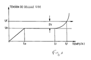
- a graphical representation of the potential difference U between the anode and the cathode measured during the test described above as a function of time is given in Figure 1.
- the potential difference U increases progressively from time 0 to time t o , t o indicating the moment when the anode working current density reaches the desired constant value of 50 kA.m -2 .
- the potential difference is then constant until time t 1 , the anode thus experiences normal operation between t o and t 1 , then after time t 1 , the potential difference increases indicating a deterioration of the anode.
- the value of the potential difference U f U o + 2 (V) is reached at time t f .
- the lifetime of the anode deduced from this curve is therefore equal to t f -t o .
- the anodes object of the present invention have a normalized service life as measured by this test significantly higher than that of anodes currently used, as will emerge from the examples given below.
- the subject of the present invention is an anode with improved longevity, characterized in that it has a standardized service life of at least 14 hm 2 .g -1 , preferably greater than 20 hm 2 .g -1 , and more preferably still greater than 25 hm 2 .g -1 , as measured by test A above and that it consists of a substrate of at least one metallic compound having an external tantalum surface, the external surface being covered with an electrocatalytic coating of iridium oxide.
- the substrate used for the anode according to the invention may consist of tantalum only. However, in order to limit manufacturing costs, this substrate can consist of at least one metallic compound other than tantalum covered with a layer of tantalum. Compounds metals other than tantalum commonly used are chosen from copper, nickel, titanium, their alloys, steel or stainless steel.
- This tantalum layer can be applied by any known method such as vacuum deposition, sputtering, deposition ionic, deposition from a reactive atmosphere, by co-lamination or electrochemically as described in the French patent application n ° 95 07158 not yet published in name of the Applicant Company.
- This layer of tantalum has a thickness between 10 ⁇ m and 500 ⁇ m, preferably between 20 ⁇ m and 200 ⁇ m, more preferably between 20 ⁇ m and 100 ⁇ m.
- the substrate used can be in the form of a plate, a hollow cylinder, a spherical particle or the like, depending on the applications envisaged for the anode.
- the coating of iridium oxide covering the substrate is such that the surface mass of iridium oxide is greater than 4 gm -2 , preferably less than 30 gm -2 and more preferably still between 5 and 20 gm - 2 .
- the present invention also relates to a method for manufacturing an anode as defined above, characterized in that the electrocatalytic coating of iridium oxide is produced in several layers by the thermal decomposition of iridium tetrachloride IrCl 4 previously applied as a coating on the substrate.
- the Applicant Company had the merit of finding that by using such a mode of formation of the electrocatalytic coating, the anode does not undergo deactivation.
- This thermal decomposition is carried out at a temperature below about 500 ° C, preferably below 475 ° C, and more preferably still between approximately 350 and 450 ° C.
- thermal decomposition is first carried out at a temperature between around 350 ° C and 400 ° C, more preferably around 350 ° C then the temperature can be increased up to about 500 ° C, preferably up to 475 ° C and above preferably still between about 350 ° C and 450 ° C.
- the first layers are obtained by thermal decomposition of a solution of IrCl 4 at a temperature between about 350 ° C and 400 ° C, more preferably about 350 ° C then the following layers are obtained with a temperature of thermal decomposition which has been increased and which is less than about 500 ° C.
- the precursor IrCl 4 is deposited on the substrate in the form of a solution in an organic solvent making it possible to lower the temperature of thermal decomposition of IrCl 4 into oxide IrO 2 .
- the solvent having this characteristic is chosen an alcoholic solvent, for example an aliphatic alcohol C 1 -C 4 such as methanol, ethanol, propanol, isopropanol, butanol 1, butanol 2, l isobutanol or tert.-butanol, or a mixture thereof.
- a mixture of isopropanol and ethanol or isopropanol and butanol-1 is used.
- the solvent is evaporated before carrying out the heat treatment in air.
- step (a) above for preparing the substrate cleaning is preferably carried out using a surfactant. Sandblasting increases the surface specific substrate and chemical pickling allows to remove the insulating oxide layer which would have formed on the tantalum surface of the electrode.
- Step (b) comprising the successive operations of applying the IrCl 4 solution, evaporating the solvent and thermal decomposition is repeated as many times as necessary to obtain the desired surface mass of oxide d 'iridium.
- the surface mass of iridium oxide is preferably from 5 to 20 g / m 2 , of course, it can be greater, but this is disadvantageous from an economic point of view.
- Step (b) is repeated at least 3 times, preferably at least 5 times.
- the application of the solution of precursor is carried out for example with a brush, or by immersion, or by any other method known in the art, especially by spraying, spraying, etc.
- the solvent can be evaporated in particular by steaming at the evaporation temperature of the solvent used.
- the thermal decomposition of the precursor is carried out in an oven, in the air.
- the decomposition thermal of the precursor is carried out at a temperature between about 350 and 400 ° C, more preferably about 350 ° C. Then for the following layers, preferably from the third layer, the temperature thermal decomposition is increased, it is lower at around 500 ° C, preferably below 475 ° C and more preferably still between approximately 350 and 450 ° C.
- the final heat treatment step (c) is conducted at a temperature below about 550 ° C, preferably less than 525 ° C and more preferably still between about 450 and 500 ° C.
- a support metal plate of 100 mm X 10 mm X 1 mm is used as substrate for the anode.
- This plate is degreased with chloroform and then subjected to sandblasting under a pressure of 5 bar using corundum (particle size: 125 ⁇ m).
- the plate is then rinsed in a tank of osmosis water under ultrasound for 10 minutes, subjected to a chemical pickling using hydrochloric or hydrofluoric acid then is rinsed.
- a precursor solution is applied by immersion or with a brush.
- the plate thus coated is steamed at 80 ° C for 5 minutes and then calcined in air in an oven at a temperature T 1 for 5 minutes.
- n being the number of layers of the precursor solution which must be applied to obtain the desired areal mass of IrO 2 .
- the plate is calcined in air for two hours at a temperature T 2 .
- the anodes thus prepared are subjected to test A as described above, whereby their lifespan and their normalized service lives are determined.
- Comparative Example 1 was repeated, except that the substrate used was NFT40 titanium and that the step of chemical pickling was conducted using hydrochloric acid at 37% at boiling point.
- Comparative Example 1 was repeated except that the substrates used were titanium alloys such as indicated in the following Table I. Chemical pickling was carried out using concentrated hydrochloric acid 37% and 36% respectively.
- Example 5 Manufacture of Ta / IrO 2 anodes
- Example 6 Manufacture of Ta / IrO 2 anodes [substrate: AISI 316 L (UNS S31603) coated with Ta, precursor: IrCl 4 ].
- Example 5 is repeated, except that one uses a stainless steel plate (316 L) covered with a tantalum layer whose thickness is indicated between parentheses in the following Table II. All anodes made in this example include 10 layers of precursor solution.
- Example 5 according to the invention Your massive 5 4.54 115.0 25.31 10 10.77 274.2 25.46 10 12.40 343.3 27.68 15 13.81 450.0 32.59 20 20.31 528.0 26.00 25 24.08 972.0 40.36 30 31.72 473.3 14.92
- Example 6 according to the invention 316L / Ta (23 ⁇ m) 10 9.39 363.0 38.64 316L / Ta (91 ⁇ m) 10 9.84 345.0 35.05 316L / Ta (93 ⁇ m) 10 9.07 273.0 30.08 316L / Ta (97 ⁇ m) 10 9.27 250.0 26.98 316L / Ta (98 ⁇ m 10 10.03 275.0 27.41 316L / Ta (99 ⁇ m) 10 9.27 253.0 27.30 Comparative Example 7 NF T40 (UNS R50100)
Landscapes
- Chemical & Material Sciences (AREA)
- Engineering & Computer Science (AREA)
- Chemical Kinetics & Catalysis (AREA)
- Electrochemistry (AREA)
- Materials Engineering (AREA)
- Metallurgy (AREA)
- Organic Chemistry (AREA)
- Electrodes For Compound Or Non-Metal Manufacture (AREA)
- Battery Electrode And Active Subsutance (AREA)
Claims (12)
- Anode mit verbesserter Lebensdauer, dadurch gekennzeichnet, daß sie aus einem Substrat aus wenigstens einer metallischen Zusammensetzung gebildet wird, die eine äußere Oberfläche aus Tantal aufweist, wobei diese äußere Oberfläche mit einer elektrokatalytischen Beschichtung aus Iridiumoxid überzogen ist und wobei sie eine normale Lebensdauer aufweist, gemessen in einem Versuch A wie in der Beschreibung angegeben, höher als 14 h.m2.g-1, vorzugsweise höher als 20 h.m2.g-1 und noch mehr bevorzugt höher als 25 h.m2.g-1.
- Anode gemäß Patentanspruch 1, dadurch gekenzeichnet, daß das Substrat aus Tantal ist.
- Anode gemäß Patentanspruch 1, dadurch gekennzeichnet, daß die metallische Zusammensetzung aus Kupfer, Nickel, Titan, deren Legierungen, Stahl oder rostfreiem Stahl ausgewählt ist.
- Anode gemäß Patentanspruch 3, dadurch gekennzeichnet, daß die Schicht aus Tantal eine Dicke zwischen 10 µm und 500 µm, vorzugsweise zwischen 20 µm und 200 µm, und noch mehr bevorzugt zwischen 20 µm und 100 µm aufweist.
- Anode nach einem der Patentansprüche 1 bis 4, dadurch gekennzeichnet, daß die Oberflächenmasse aus Iridiumoxid, die als Beschichtung auf das Substrat aufgetragen ist, größer als 4 g.m-2 ist, vorzugsweise niedriger als 30 g.m-2, und noch mehr bevorzugt noch zwischen 5 und 20 g.m-2 liegt.
- Herstellungsverfahren einer Anode nach einem der Patentansprüche 1 bis 5, dadurch gekennzeichnet, daß die elektrokatalytische Beschichtung aus Iridiumoxid in mehreren Schichten durch thermische Zersetzung von Iridiumtetrachlorid IrCl4 durchgeführt wird, vorzugsweise angewandt als Beschichtung auf dem Substrat.
- Verfahren nach einem der Patentansprüche 1 bis 6,dadurch gekennzeichnet, daß die thermische Zersetzung von IrCl4 bei einer Temperatur ausgeführt wird, die niedriger als ca. 500° C ist, vorzugsweise niedriger als 475° C und noch mehr bevorzugt zwischen ca. 350° C und 450° C liegt.
- Verfahren gemäß Patentanspruch 7, dadurch gekennzeichnet, daß die thermische Zersetzung von IrCl4 zuerst bei einer Temperatur zwischen ca. 350 und 400° C durchgeführt wird, vorzugsweise ca. 350° C, um die ersten Schichten von Iridiumoxid zu bilden, und um jegliche Bildung von thermischem Tantaloxid zu vermeiden, das nicht leitfähig ist, diese Temperatur erhöht wird, bis zu einer Temperatur, die geringer als ca. 500° C ist, vorzugsweise geringer als ca. 475° C und noch mehr bevorzugt zwischen ca. 350 und 450° C ist, um die höheren Schichten aus Iridiumoxid zu bilden.
- Verfahren nach einem der Patentansprüche 6 und 8, dadurch gekennzeichnet, daß der Zwischenstoff IrCl4 in Form einer Lösung in einem organischen Lösungsmittel abgelagert wird, das erlaubt, die thermische Zersetzungstemperatur von IrCl4 in Oxid IrO2 zu senken, vorzugsweise in einem alkoholischen Lösungsmittel, und noch mehr bevorzugt in einem Gemisch aus Ethanol und Isopropanol, wobei das genannte Lösungsmittel vor der thermischen Zersetzung verdunstet wird.
- Verfahren nach einem der Patentansprüche 6 bis 9, dadurch gekennzeichnet, daß es die folgenden Schritte umfasst:(a) Vorbereitung des Substrates, insbesondere bestehend aus Waschen, Sandstrahlen und chemischem Beizen;(b) Abscheidung der Iridiumoxid-Schicht durch Einsatz der IrCl4 Lösung in einem organischen Lösungsmittel auf dem Substrat, Verdampfen des Lösungsmittels und thermische Zersetzung von IrCl4;(c) thermische Endbehandlung, wobei der Verfahrensschritt (b) so oft wie notwendig wiederholt wird, um die gewünschte Oberflächenmasse von Iridiumoxid zu erhalten.
- Verfahren gemäß Patentanspruch 10, dadurch gekennzeichnet, daß der Verfahrensschritt (b) mindestens dreimal wiederholt wird, vorzugsweise mindestens fünfmal, und daß die thermische Zersetzungstemperatur zwischen 350 und 400° C liegt, vorzugsweise bei 350° C mindestens für die zwei ersten Male, bei dem der Verfahrensschritt (b) durchgeführt wird, anschließend der Verfahrensschritt (b) wiederholt wird, wobei die thermische Zersetzungstemperatur erhöht wird, wobei diese dann niedriger als ca. 500° C ist, vorzugsweise niedriger als 475° C und noch mehr bevorzugt zwischen 350 und 450° C liegt.
- Verfahren gemäß Patentanspruch 10 oder 11, dadurch gekennzeichnet, daß der Verfahrensschritt (c) der thermischen Endbehandlung bei einer Temperatur geringer als ca. 550° C ausgeführt wird, vorzugsweise niedriger als 525° C, und noch mehr bevorzugt zwischen 450 und 500° C.
Applications Claiming Priority (3)
| Application Number | Priority Date | Filing Date | Title |
|---|---|---|---|
| FR9605916A FR2748495B1 (fr) | 1996-05-13 | 1996-05-13 | Anode a longevite amelioree et son procede de fabrication |
| FR9605916 | 1996-05-13 | ||
| PCT/FR1997/000836 WO1997043465A1 (fr) | 1996-05-13 | 1997-05-12 | Anode a longevite amelioree et son procede de fabrication |
Publications (2)
| Publication Number | Publication Date |
|---|---|
| EP0925387A1 EP0925387A1 (de) | 1999-06-30 |
| EP0925387B1 true EP0925387B1 (de) | 2000-09-20 |
Family
ID=9492070
Family Applications (1)
| Application Number | Title | Priority Date | Filing Date |
|---|---|---|---|
| EP97924074A Expired - Lifetime EP0925387B1 (de) | 1996-05-13 | 1997-05-12 | Anode mit verbesserter lebensdauer und deren herstellungsverfahren |
Country Status (5)
| Country | Link |
|---|---|
| EP (1) | EP0925387B1 (de) |
| DE (1) | DE69703163T2 (de) |
| ES (1) | ES2152673T3 (de) |
| FR (1) | FR2748495B1 (de) |
| WO (1) | WO1997043465A1 (de) |
Families Citing this family (3)
| Publication number | Priority date | Publication date | Assignee | Title |
|---|---|---|---|---|
| FR2811339B1 (fr) * | 2000-07-07 | 2003-08-29 | Electricite De France | Procede de preparation de materiaux metalliques pour leur utilisation comme electrodes |
| FR2811338B1 (fr) * | 2000-11-10 | 2003-02-14 | Electricite De France | Procede de preparation de materiaux metalliques pour leur utilisation comme electrodes |
| WO2021117311A1 (ja) * | 2019-12-13 | 2021-06-17 | パナソニックIpマネジメント株式会社 | 電解用電極 |
Family Cites Families (4)
| Publication number | Priority date | Publication date | Assignee | Title |
|---|---|---|---|---|
| US4257856A (en) * | 1979-10-17 | 1981-03-24 | Bell Telephone Laboratories, Incorporated | Electrolytic process useful for the electrolysis of water |
| GB8903322D0 (en) * | 1989-02-14 | 1989-04-05 | Ici Plc | Electrolytic process |
| DE3905082A1 (de) * | 1989-02-18 | 1990-08-23 | Bayer Ag | Formstabile anoden und deren verwendung bei der herstellung von alkalidichromaten und chromsaeure |
| JP3044797B2 (ja) * | 1991-02-04 | 2000-05-22 | ダイソー株式会社 | 酸素発生用陽極の製法 |
-
1996
- 1996-05-13 FR FR9605916A patent/FR2748495B1/fr not_active Expired - Fee Related
-
1997
- 1997-05-12 DE DE69703163T patent/DE69703163T2/de not_active Expired - Lifetime
- 1997-05-12 EP EP97924074A patent/EP0925387B1/de not_active Expired - Lifetime
- 1997-05-12 WO PCT/FR1997/000836 patent/WO1997043465A1/fr not_active Ceased
- 1997-05-12 ES ES97924074T patent/ES2152673T3/es not_active Expired - Lifetime
Also Published As
| Publication number | Publication date |
|---|---|
| FR2748495A1 (fr) | 1997-11-14 |
| ES2152673T3 (es) | 2001-02-01 |
| EP0925387A1 (de) | 1999-06-30 |
| FR2748495B1 (fr) | 1998-07-17 |
| DE69703163T2 (de) | 2001-05-17 |
| DE69703163D1 (de) | 2000-10-26 |
| WO1997043465A1 (fr) | 1997-11-20 |
Similar Documents
| Publication | Publication Date | Title |
|---|---|---|
| EP1125005B1 (de) | Kathode für die elektrolyse von wässrigen lösungen | |
| EP3277855B1 (de) | Cermetelektrodenmaterial | |
| EP0113931B1 (de) | Kathode zur elektrolytischen Herstellung von Wasserstoff und ihre Anwendung | |
| JP2010236091A (ja) | 耐食性導電部材とその製造方法及び燃料電池 | |
| WO2011003974A1 (fr) | Procede de depôt par pulverisation cathodique, produit obtenu et cible de pulverisation | |
| FR2463496A1 (fr) | Procede de deposition d'un film metallique poreux sur un substrat metallique ou plastique et application a la fabrication de condensateurs electrolytiques | |
| EA012053B1 (ru) | Способ формирования электрокаталитической поверхности на электроде и электрод | |
| EP0556136A1 (de) | Elektrodenfolie für Elektrolytkondensator und Herstellungsverfahren | |
| EP0023368A1 (de) | Kathode für die elektrolytische Herstellung von Wasserstoff | |
| KR20160028997A (ko) | 전해장치용 내부식성 및 전기 전도성 표면 | |
| FR2599386A1 (fr) | Electrodes durables pour l'electrolyse et procede pour leur fabrication | |
| EP0707095B1 (de) | Elektrode für elektrochemisches Verfahren und deren Verwendung | |
| EP0867527B1 (de) | Elektrode mit katalytischer Beschichtung für elektrochemische Prozesse und Verfahren zu deren Herstellung | |
| EP0131978B1 (de) | Herstellungsverfahren einer Elektrode für elektrochemische Verfahren und Kathode für die elektrolytische Wasserstofferzeugung | |
| EP0925387A1 (de) | Anode mit verbesserter lebensdauer und deren herstellungsverfahren | |
| FR2461023A1 (fr) | Procede de preparation de substrats conducteurs et d'electrodes pour l'electrolyse d'une saumure, et l'electrode a faible surtension ainsi obtenue | |
| TWI490372B (zh) | 釋氫用的電極及其製法和使用 | |
| EP0982412A1 (de) | Verfahren für die Verbesserung der Haftung von metallischen Partikeln auf einen Kohlenstoffsubstrat | |
| EP1788110B1 (de) | Anlaufbeständige Silberbeschichtung, Abscheidungsverfahren und Verwendung. | |
| EP0209427A1 (de) | Kathode für Elektrolyse und Herstellungsverfahren dieser Kathode | |
| EP1205577A1 (de) | Verfahren zur Herstellung von metallischen Materialien und ihre Anwendung als Elektroden | |
| EP1170399A1 (de) | Verfahren zur Behandlung metallischer Werkstoffe für ihre Verwendung als Elektroden | |
| CA2801793C (en) | Substrate coating on one or more sides | |
| CN108866610B (zh) | 一种电解阳极 | |
| FR2689301A1 (fr) | Procédé d'obtention d'une feuille d'aluminium pour électrodes de condensateur électrolytique, feuille pour la fabrication d'électrodes de condensateur électrolytique et condensateur électrolytique obtenu. |
Legal Events
| Date | Code | Title | Description |
|---|---|---|---|
| PUAI | Public reference made under article 153(3) epc to a published international application that has entered the european phase |
Free format text: ORIGINAL CODE: 0009012 |
|
| 17P | Request for examination filed |
Effective date: 19981102 |
|
| AK | Designated contracting states |
Kind code of ref document: A1 Designated state(s): BE CH DE ES FR GB IT LI NL |
|
| GRAG | Despatch of communication of intention to grant |
Free format text: ORIGINAL CODE: EPIDOS AGRA |
|
| 17Q | First examination report despatched |
Effective date: 19991118 |
|
| GRAG | Despatch of communication of intention to grant |
Free format text: ORIGINAL CODE: EPIDOS AGRA |
|
| GRAH | Despatch of communication of intention to grant a patent |
Free format text: ORIGINAL CODE: EPIDOS IGRA |
|
| GRAH | Despatch of communication of intention to grant a patent |
Free format text: ORIGINAL CODE: EPIDOS IGRA |
|
| GRAA | (expected) grant |
Free format text: ORIGINAL CODE: 0009210 |
|
| AK | Designated contracting states |
Kind code of ref document: B1 Designated state(s): BE CH DE ES FR GB IT LI NL |
|
| RIN1 | Information on inventor provided before grant (corrected) |
Inventor name: TAXIL, PIERRE Inventor name: COMNINELLIS, CHRISTOS Inventor name: SAVALL, ANDRE Inventor name: CARDARELLI, FRANCOIS Inventor name: MANOLI, GEORGIA Inventor name: LECLERC, OLIVIER Inventor name: REID, VERONIQUE |
|
| REG | Reference to a national code |
Ref country code: CH Ref legal event code: EP |
|
| REF | Corresponds to: |
Ref document number: 69703163 Country of ref document: DE Date of ref document: 20001026 |
|
| ITF | It: translation for a ep patent filed | ||
| GBT | Gb: translation of ep patent filed (gb section 77(6)(a)/1977) |
Effective date: 20001220 |
|
| REG | Reference to a national code |
Ref country code: ES Ref legal event code: FG2A Ref document number: 2152673 Country of ref document: ES Kind code of ref document: T3 |
|
| PG25 | Lapsed in a contracting state [announced via postgrant information from national office to epo] |
Ref country code: BE Free format text: LAPSE BECAUSE OF NON-PAYMENT OF DUE FEES Effective date: 20010531 |
|
| PG25 | Lapsed in a contracting state [announced via postgrant information from national office to epo] |
Ref country code: LI Free format text: LAPSE BECAUSE OF NON-PAYMENT OF DUE FEES Effective date: 20010611 Ref country code: CH Free format text: LAPSE BECAUSE OF NON-PAYMENT OF DUE FEES Effective date: 20010611 |
|
| PLBE | No opposition filed within time limit |
Free format text: ORIGINAL CODE: 0009261 |
|
| STAA | Information on the status of an ep patent application or granted ep patent |
Free format text: STATUS: NO OPPOSITION FILED WITHIN TIME LIMIT |
|
| 26N | No opposition filed | ||
| BERE | Be: lapsed |
Owner name: ELECTRICITE DE FRANCE SERVICE NATIONAL Effective date: 20010531 |
|
| REG | Reference to a national code |
Ref country code: GB Ref legal event code: IF02 |
|
| REG | Reference to a national code |
Ref country code: CH Ref legal event code: PL |
|
| PGFP | Annual fee paid to national office [announced via postgrant information from national office to epo] |
Ref country code: DE Payment date: 20120514 Year of fee payment: 16 |
|
| PGFP | Annual fee paid to national office [announced via postgrant information from national office to epo] |
Ref country code: GB Payment date: 20120521 Year of fee payment: 16 Ref country code: FR Payment date: 20120615 Year of fee payment: 16 |
|
| PGFP | Annual fee paid to national office [announced via postgrant information from national office to epo] |
Ref country code: IT Payment date: 20120522 Year of fee payment: 16 |
|
| PGFP | Annual fee paid to national office [announced via postgrant information from national office to epo] |
Ref country code: ES Payment date: 20120524 Year of fee payment: 16 |
|
| PGFP | Annual fee paid to national office [announced via postgrant information from national office to epo] |
Ref country code: NL Payment date: 20130412 Year of fee payment: 17 |
|
| GBPC | Gb: european patent ceased through non-payment of renewal fee |
Effective date: 20130512 |
|
| PG25 | Lapsed in a contracting state [announced via postgrant information from national office to epo] |
Ref country code: DE Free format text: LAPSE BECAUSE OF NON-PAYMENT OF DUE FEES Effective date: 20131203 |
|
| PG25 | Lapsed in a contracting state [announced via postgrant information from national office to epo] |
Ref country code: IT Free format text: LAPSE BECAUSE OF NON-PAYMENT OF DUE FEES Effective date: 20130512 |
|
| REG | Reference to a national code |
Ref country code: FR Ref legal event code: ST Effective date: 20140131 |
|
| REG | Reference to a national code |
Ref country code: DE Ref legal event code: R119 Ref document number: 69703163 Country of ref document: DE Effective date: 20131203 |
|
| PG25 | Lapsed in a contracting state [announced via postgrant information from national office to epo] |
Ref country code: GB Free format text: LAPSE BECAUSE OF NON-PAYMENT OF DUE FEES Effective date: 20130512 |
|
| PG25 | Lapsed in a contracting state [announced via postgrant information from national office to epo] |
Ref country code: FR Free format text: LAPSE BECAUSE OF NON-PAYMENT OF DUE FEES Effective date: 20130531 |
|
| REG | Reference to a national code |
Ref country code: ES Ref legal event code: FD2A Effective date: 20140610 |
|
| PG25 | Lapsed in a contracting state [announced via postgrant information from national office to epo] |
Ref country code: ES Free format text: LAPSE BECAUSE OF NON-PAYMENT OF DUE FEES Effective date: 20130513 |
|
| REG | Reference to a national code |
Ref country code: NL Ref legal event code: V1 Effective date: 20141201 |
|
| PG25 | Lapsed in a contracting state [announced via postgrant information from national office to epo] |
Ref country code: NL Free format text: LAPSE BECAUSE OF NON-PAYMENT OF DUE FEES Effective date: 20141201 |