EP0922937A2 - Tube pour débitmètre ultrasonique - Google Patents
Tube pour débitmètre ultrasonique Download PDFInfo
- Publication number
- EP0922937A2 EP0922937A2 EP98122721A EP98122721A EP0922937A2 EP 0922937 A2 EP0922937 A2 EP 0922937A2 EP 98122721 A EP98122721 A EP 98122721A EP 98122721 A EP98122721 A EP 98122721A EP 0922937 A2 EP0922937 A2 EP 0922937A2
- Authority
- EP
- European Patent Office
- Prior art keywords
- wall
- measuring tube
- flow meter
- meter according
- structuring
- Prior art date
- Legal status (The legal status is an assumption and is not a legal conclusion. Google has not performed a legal analysis and makes no representation as to the accuracy of the status listed.)
- Withdrawn
Links
Images

Classifications
-
- G—PHYSICS
- G01—MEASURING; TESTING
- G01F—MEASURING VOLUME, VOLUME FLOW, MASS FLOW OR LIQUID LEVEL; METERING BY VOLUME
- G01F1/00—Measuring the volume flow or mass flow of fluid or fluent solid material wherein the fluid passes through a meter in a continuous flow
- G01F1/66—Measuring the volume flow or mass flow of fluid or fluent solid material wherein the fluid passes through a meter in a continuous flow by measuring frequency, phase shift or propagation time of electromagnetic or other waves, e.g. using ultrasonic flowmeters
- G01F1/662—Constructional details
Definitions
- the invention relates to a flow meter in the form of a measuring tube through which a medium to be measured flows the flow medium is sonicated with ultrasound and that emitted ultrasound signal detected in different ways becomes.
- the principle of wave propagation of ultrasound in the moving medium is used to measure the flow velocity v of a medium and thus the volume V through a pipe.
- wave packets are sent and received upstream and downstream and the respective transit times t ⁇ and t ⁇ are determined.
- the speed v is proportional to the difference between the reciprocal running times (1 / t ⁇ -1 / t ⁇ ).
- the phase and the amplitude of a reflected wave depend on the material properties of the sound-conducting medium, the material used as the reflector and on the angle ⁇ between the perpendicular to the reflector and the incident sound signal.
- ⁇ L , G ArcSin ⁇ L, I ⁇ L, II
- ⁇ T, G ArcSin ⁇ L, I ⁇ T, II
- ⁇ L or ⁇ T is the velocity of the longitudinal or transverse wave in the respective material.
- the critical angle for the longitudinal wave is generally smaller than the critical angle for the transverse wave. If the angle of incidence is greater than ⁇ T, G ' , there is total reflection. Then ⁇ T, G ' is the so-called critical angle for total reflection and the reflection coefficient becomes 1.
- the incident one splits Longitudinal wave in the solid state in this way into a longitudinal wave and a transverse wave that this together with the incident wave is a surface wave, a Rayleigh wave, can form.
- the strongest surface wave is created at an angle of incidence slightly above the critical angle. condition for the excitation is that the so-called incident wave equal to the wavelength of Rayleigh's Surface wave is.
- the speed of the surface wave depends on the longitudinal and transverse wave speeds in the reflector material.
- the beam displacement takes the one reflected at the intended location Longitudinal wave energy away and leads there a level loss.
- This level loss and the simultaneous Generation of the shifted wave lead to a phase curve, which has a strong unfavorable influence on the measuring accuracy because it has the maturity differences that make up the flowed through volume is calculated, falsified.
- measuring tubes for ultrasonic flow measurements which have a relatively small operating range have different sound velocities in media.
- the object of the invention is to provide a flow meter with minimized Overall length or increased measuring range with respect to Speed of sound in the measuring media or with increased measuring accuracy to provide.
- the invention is based on the knowledge that the disruptive beam displacement of the ultrasound signal can be suppressed by structuring the outer wall, ie the wall not in contact with the medium, of the measuring tube.
- the structuring extends so far to the inner wall of the measuring tube that it covers the spatial areas required for the formation of the beam dislocation.
- the inner wall of the measuring tube is not covered by the structuring, so it remains unstructured within a certain wall thickness. Because the structure of the inner wall of the measuring tube coming into contact with the medium is not changed by the structuring, there is the advantage that the function of the measuring tube is not disturbed.
- the wall thickness can be, for example, in a range of 0.25 ... 2 wavelengths, it can be adapted to the requirement profile of the measuring tube. For example, in the case of a strong effect of the beam dislocation, the structuring can be brought closer to the inner wall than with only a slight splitting off of the ultrasound signal.
- the nature of the medium can also influence the dimensioning of the wall thickness, for example if the medium has an abrasive effect on the measuring tube, the wall thickness should be high enough so that no leaks occur in the measuring tube.
- the structuring can take place, for example, in that Bores, for example blind holes, or cuts, for example saw cuts or millings, in the outer wall of the measuring tube.
- Bores for example blind holes
- cuts for example saw cuts or millings
- the borehole or cutting pattern can be in any Matched to the shape of the respective measuring tube be, for example, in terms of pattern, diameter, depth and direction of the holes or direction, width and depth the cuts.
- the structuring is advantageously carried out by introducing the individual components of the structuring, for example individual bores or cuts, at a distance of a few wavelength fractions of the interfering sound wave in the measuring tube.
- the propagation of an ultrasonic wave on the measuring tube is suppressed from the point at which it hits the measuring tube. It is advantageous if the structuring pattern is regular, for example by regularly arranging bores or cuts.
- this type of suppression of the disruptive beam dislocation own the individual components of the structuring advantageously a varying distance with each other. The distances can also be irregular.
- the individual Components of the structuring have the same dimensions, for example if the individual holes of a borehole pattern the same depth and / or the same diameter have, or the individual cuts of a pattern have the same depth and / or the same width.
- the structuring is arranged in this way is that that is projected onto the inner wall of the measuring tube Pattern of structuring with the shape of the on the Measuring tube impinging wave fronts of the ultrasonic signal matches as much as possible. If necessary, an additional one Angular misalignment between the projected pattern and the Wavefront occur.
- Cavities in the measuring tube created by the structuring can be filled with material different from the wall material be. It is advantageous if the filling material is a has a high damping constant for acoustic waves.
- a cover plate can be placed on the structure are, for example by welding a metal plate, with the outer wall of the measuring tube, for example ends flush. This can structure the mechanical or chemical influences in the vicinity of the measuring tube to be protected.
- the reflective areas of the measuring tube are realized by special guide reflectors.
- a variant of a measuring tube 1 is shown schematically in FIG shown, the transmitter / receiver units 2, 3, wherein is either sounded in one direction or through the Use of combined transmitter / receiver units 2, 3 alternately in the opposite direction from left to right or right is sounded to the left through the medium flowing through.
- the course of the ultrasound signal 6 is through a family of lines indicated.
- the special guide reflectors 4, 5 serve for this purpose, those emitted by the transmitting / receiving units 2, 3 or received ultrasonic signals in a rough direction to lead. In between, approximately in the middle of the figure shown the ultrasonic signal 6 on a part of the inner wall of the Measuring tube 1, in this case reflected on the upper wall.
- FIG. 2 shows a streak image of an ultrasound beam, which is reflected solid / liquid at an interface.
- the beam dislocation 8 results from the splitting off of a Surface wave.
- the solid is below a drawn line and the fluid above located on this line.
- An incident beam also forms a surface normal 9 an angle of incidence 7, the reflected beam with the surface normal 9 an angle of reflection 71 forms.
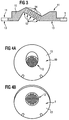
- Figure 3 shows schematically as a sectional view in side view a special guide reflector 10 according to the invention as part of a measuring tube 1 with through the introduction of boreholes 12 the outer wall 13 of the reflector 10 implemented structuring.
- the boreholes 12 are perpendicular to that which they have drilled behind Measuring tube outer wall 13 introduced.
- the shape of the inner wall 11 of the reflector 1 remains unchanged.
- the cavities formed by the holes 12 are with Filling material 14 filled.
- FIG. 4a shows a reflector 10 in a view of its outer wall 13.
- the reflector 10 is through holes 12 that are marked here by a common arrow, from structured the outer wall 13 forth.
- the diameter of the boreholes 12 is 1 mm.
- FIG. 4b shows a reflector when looking at the outer wall 13 10 as in Figure 4a in supervision parallel to the course of the Boreholes 12 indicated by a common arrow are. You can recognize that by regular arrangement of the Boreholes 12 structuring.
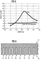
- Figure 5 shows by plotting the deviation of the measured Flow from a reference value in% against the Runtime of the ultrasound signal in ⁇ s the main impact the invention.
- the two graphs show that for one According to the invention, the flow-through numbers are drilled behind the reflector over a wide range of speeds of sound, which are converted here into terms of the ultrasound signal have been largely consistent during the deviation the flow measurements of a reflector a considerable one Dependence on the speed of sound shows.
- Figure 6 shows schematically as a sectional view in side view structuring the outer wall 13 of the measuring tube 1 with a Arrangement of saw cuts 15 that are perpendicular to the inner wall 11 of the measuring tube 1 are introduced and the one to the other have variable spacing.
Landscapes
- Physics & Mathematics (AREA)
- Electromagnetism (AREA)
- Fluid Mechanics (AREA)
- General Physics & Mathematics (AREA)
- Length Measuring Devices Characterised By Use Of Acoustic Means (AREA)
- Investigating Or Analyzing Materials By The Use Of Ultrasonic Waves (AREA)
Applications Claiming Priority (2)
| Application Number | Priority Date | Filing Date | Title |
|---|---|---|---|
| DE1997155152 DE19755152C1 (de) | 1997-12-11 | 1997-12-11 | Ultraschall-Durchflußmeßrohr |
| DE19755152 | 1997-12-11 |
Publications (2)
| Publication Number | Publication Date |
|---|---|
| EP0922937A2 true EP0922937A2 (fr) | 1999-06-16 |
| EP0922937A3 EP0922937A3 (fr) | 2000-07-05 |
Family
ID=7851618
Family Applications (1)
| Application Number | Title | Priority Date | Filing Date |
|---|---|---|---|
| EP98122721A Withdrawn EP0922937A3 (fr) | 1997-12-11 | 1998-11-30 | Tube pour débitmètre ultrasonique |
Country Status (2)
| Country | Link |
|---|---|
| EP (1) | EP0922937A3 (fr) |
| DE (1) | DE19755152C1 (fr) |
Cited By (2)
| Publication number | Priority date | Publication date | Assignee | Title |
|---|---|---|---|---|
| DE102018133066A1 (de) * | 2018-12-20 | 2020-06-25 | Endress+Hauser Flowtec Ag | Ultraschall-Messgerät |
| CN113242959B (zh) * | 2018-12-20 | 2024-05-28 | 恩德斯+豪斯流量技术股份有限公司 | 超声仪器 |
Citations (2)
| Publication number | Priority date | Publication date | Assignee | Title |
|---|---|---|---|---|
| EP0212470A2 (fr) * | 1985-08-12 | 1987-03-04 | Panametrics, Inc. | Appareil pour mesurer les caractéristiques d'un fluide en utilisant des signaux de surface à interrogation de volume |
| DE3911408A1 (de) * | 1989-04-07 | 1990-10-11 | Siemens Ag | Messrohr fuer ultraschall-durchflussmessungen |
Family Cites Families (1)
| Publication number | Priority date | Publication date | Assignee | Title |
|---|---|---|---|---|
| DE4336370C1 (de) * | 1993-10-25 | 1995-02-02 | Siemens Ag | Vorrichtung zur Durchflußmessung |
-
1997
- 1997-12-11 DE DE1997155152 patent/DE19755152C1/de not_active Expired - Fee Related
-
1998
- 1998-11-30 EP EP98122721A patent/EP0922937A3/fr not_active Withdrawn
Patent Citations (2)
| Publication number | Priority date | Publication date | Assignee | Title |
|---|---|---|---|---|
| EP0212470A2 (fr) * | 1985-08-12 | 1987-03-04 | Panametrics, Inc. | Appareil pour mesurer les caractéristiques d'un fluide en utilisant des signaux de surface à interrogation de volume |
| DE3911408A1 (de) * | 1989-04-07 | 1990-10-11 | Siemens Ag | Messrohr fuer ultraschall-durchflussmessungen |
Cited By (4)
| Publication number | Priority date | Publication date | Assignee | Title |
|---|---|---|---|---|
| DE102018133066A1 (de) * | 2018-12-20 | 2020-06-25 | Endress+Hauser Flowtec Ag | Ultraschall-Messgerät |
| CN113242959A (zh) * | 2018-12-20 | 2021-08-10 | 恩德斯+豪斯流量技术股份有限公司 | 超声仪器 |
| US11982647B2 (en) | 2018-12-20 | 2024-05-14 | Endress+Hauser Flowtec Ag | Ultrasonic measuring device |
| CN113242959B (zh) * | 2018-12-20 | 2024-05-28 | 恩德斯+豪斯流量技术股份有限公司 | 超声仪器 |
Also Published As
| Publication number | Publication date |
|---|---|
| DE19755152C1 (de) | 1999-05-06 |
| EP0922937A3 (fr) | 2000-07-05 |
Similar Documents
| Publication | Publication Date | Title |
|---|---|---|
| DE4430223A1 (de) | Ultraschallströmungs-Meßverfahren und Vorrichtung zur Durchführung des Verfahrens | |
| DE3020282C2 (de) | Durchfluß-Strömungsmesser mit Ultraschall | |
| DE4010148A1 (de) | Verbesserung fuer einen ultraschall-gas-/fluessigkeits-durchflussmesser | |
| EP2440888B1 (fr) | Procédé de mesure d'un mesurande | |
| DE1958235A1 (de) | Verfahren und Geraet zur Messung von Stroemungen in Leitungen | |
| EP1716394A2 (fr) | Debitmetre a ultrasons dote d'elements d'emission et de reception entrecroises | |
| EP3577427A1 (fr) | Compteur à ultrasons et procédé d'acquisition d'une grandeur de débit | |
| DE102014115203B3 (de) | Verfahren und Anordnung zur Ultraschall-Clamp-on-Durchflussmessung und Schaltungsanordnung zur Steuerung einer Ultraschall-Clamp-on-Durchflussmessung | |
| EP1955019B1 (fr) | Dispositif de mesure à ultrasons pour déterminer et/ou surveiller l'écoulement volumique ou massique d'une substance dans une conduite tubulaire | |
| EP2656017A1 (fr) | Élément de couplage d'un transducteur ultrasonique pour un débitmètre à ultrasons | |
| DE102011089685A1 (de) | Messanordnung zur Bestimmung eines Füllstands und/oder einer Konzentration einer Flüssigkeit | |
| DE102009046159A1 (de) | Ultraschall-Durchfluss- und Partikelmesssystem | |
| DE19944047A1 (de) | Vorrichtung zur Messung der Konzentration oder Dichte sowie von Partikeln | |
| DE102020123992B3 (de) | THz-Messvorrichtung und THz-Messverfahren zur Vermessung von Prüfobjekten, insbesondere Rohren | |
| DE102010063789A1 (de) | Ultraschall-Durchflussmessgerät | |
| EP3867636B1 (fr) | Procédé et dispositif de détermination non invasive de caractéristiques d'un courant polyphasé | |
| DE2656857C2 (de) | Wandler für Schiffs-Ultraschall- Dopplernavigationssysteme | |
| DE19934212B4 (de) | Verfahren und Vorrichtung zum Messen der Strömungsgeschwindigkeit eines Fluidstromes | |
| EP0922937A2 (fr) | Tube pour débitmètre ultrasonique | |
| DE3911408A1 (de) | Messrohr fuer ultraschall-durchflussmessungen | |
| EP3405781B1 (fr) | Dispositif de détermination de caractéristiques d'un milieu, comprenant un élément d'amortissement et/ou un élément de guidage ouvert | |
| DE3013482A1 (de) | Ultraschallkopf mit elektroakustischem wandler fuer ultraschall-durchflussmessungen nach dem doppler-prinzip | |
| DE102015106695A1 (de) | Verfahren und Vorrichtung zur Durchflussmessung | |
| DE102016116070A1 (de) | Verfahren zur Erkennung von Fremdkörpern bei einem Vortex-Durchflussmessgerät, ein Vortex-Durchflussmessgerät, eine Anordnung mit einem Vortex-Durchflussmessgerät und eine Abfüllanlage mit einer Anordnung | |
| DE102011004830B4 (de) | Phasenverfahren zur Messung der Ausbreitungsgeschwindigkeit von Schallwellen mit dynamischem Messfenster |
Legal Events
| Date | Code | Title | Description |
|---|---|---|---|
| PUAI | Public reference made under article 153(3) epc to a published international application that has entered the european phase |
Free format text: ORIGINAL CODE: 0009012 |
|
| AK | Designated contracting states |
Kind code of ref document: A2 Designated state(s): CH DE DK GB LI NL |
|
| AX | Request for extension of the european patent |
Free format text: AL;LT;LV;MK;RO;SI |
|
| PUAL | Search report despatched |
Free format text: ORIGINAL CODE: 0009013 |
|
| AK | Designated contracting states |
Kind code of ref document: A3 Designated state(s): AT BE CH CY DE DK ES FI FR GB GR IE IT LI LU MC NL PT SE |
|
| AX | Request for extension of the european patent |
Free format text: AL;LT;LV;MK;RO;SI |
|
| 17P | Request for examination filed |
Effective date: 20001106 |
|
| AKX | Designation fees paid | ||
| RBV | Designated contracting states (corrected) |
Designated state(s): CH DE DK GB LI NL |
|
| REG | Reference to a national code |
Ref country code: DE Ref legal event code: 8566 |
|
| 17Q | First examination report despatched |
Effective date: 20070413 |
|
| STAA | Information on the status of an ep patent application or granted ep patent |
Free format text: STATUS: THE APPLICATION IS DEEMED TO BE WITHDRAWN |
|
| 18D | Application deemed to be withdrawn |
Effective date: 20070601 |