EP0922937A2 - Ultrasonic flow metering tube - Google Patents
Ultrasonic flow metering tube Download PDFInfo
- Publication number
- EP0922937A2 EP0922937A2 EP98122721A EP98122721A EP0922937A2 EP 0922937 A2 EP0922937 A2 EP 0922937A2 EP 98122721 A EP98122721 A EP 98122721A EP 98122721 A EP98122721 A EP 98122721A EP 0922937 A2 EP0922937 A2 EP 0922937A2
- Authority
- EP
- European Patent Office
- Prior art keywords
- wall
- measuring tube
- flow meter
- meter according
- structuring
- Prior art date
- Legal status (The legal status is an assumption and is not a legal conclusion. Google has not performed a legal analysis and makes no representation as to the accuracy of the status listed.)
- Withdrawn
Links
Images

Classifications
-
- G—PHYSICS
- G01—MEASURING; TESTING
- G01F—MEASURING VOLUME, VOLUME FLOW, MASS FLOW OR LIQUID LEVEL; METERING BY VOLUME
- G01F1/00—Measuring the volume flow or mass flow of fluid or fluent solid material wherein the fluid passes through a meter in a continuous flow
- G01F1/66—Measuring the volume flow or mass flow of fluid or fluent solid material wherein the fluid passes through a meter in a continuous flow by measuring frequency, phase shift or propagation time of electromagnetic or other waves, e.g. using ultrasonic flowmeters
- G01F1/662—Constructional details
Definitions
- the invention relates to a flow meter in the form of a measuring tube through which a medium to be measured flows the flow medium is sonicated with ultrasound and that emitted ultrasound signal detected in different ways becomes.
- the principle of wave propagation of ultrasound in the moving medium is used to measure the flow velocity v of a medium and thus the volume V through a pipe.
- wave packets are sent and received upstream and downstream and the respective transit times t ⁇ and t ⁇ are determined.
- the speed v is proportional to the difference between the reciprocal running times (1 / t ⁇ -1 / t ⁇ ).
- the phase and the amplitude of a reflected wave depend on the material properties of the sound-conducting medium, the material used as the reflector and on the angle ⁇ between the perpendicular to the reflector and the incident sound signal.
- ⁇ L , G ArcSin ⁇ L, I ⁇ L, II
- ⁇ T, G ArcSin ⁇ L, I ⁇ T, II
- ⁇ L or ⁇ T is the velocity of the longitudinal or transverse wave in the respective material.
- the critical angle for the longitudinal wave is generally smaller than the critical angle for the transverse wave. If the angle of incidence is greater than ⁇ T, G ' , there is total reflection. Then ⁇ T, G ' is the so-called critical angle for total reflection and the reflection coefficient becomes 1.
- the incident one splits Longitudinal wave in the solid state in this way into a longitudinal wave and a transverse wave that this together with the incident wave is a surface wave, a Rayleigh wave, can form.
- the strongest surface wave is created at an angle of incidence slightly above the critical angle. condition for the excitation is that the so-called incident wave equal to the wavelength of Rayleigh's Surface wave is.
- the speed of the surface wave depends on the longitudinal and transverse wave speeds in the reflector material.
- the beam displacement takes the one reflected at the intended location Longitudinal wave energy away and leads there a level loss.
- This level loss and the simultaneous Generation of the shifted wave lead to a phase curve, which has a strong unfavorable influence on the measuring accuracy because it has the maturity differences that make up the flowed through volume is calculated, falsified.
- measuring tubes for ultrasonic flow measurements which have a relatively small operating range have different sound velocities in media.
- the object of the invention is to provide a flow meter with minimized Overall length or increased measuring range with respect to Speed of sound in the measuring media or with increased measuring accuracy to provide.
- the invention is based on the knowledge that the disruptive beam displacement of the ultrasound signal can be suppressed by structuring the outer wall, ie the wall not in contact with the medium, of the measuring tube.
- the structuring extends so far to the inner wall of the measuring tube that it covers the spatial areas required for the formation of the beam dislocation.
- the inner wall of the measuring tube is not covered by the structuring, so it remains unstructured within a certain wall thickness. Because the structure of the inner wall of the measuring tube coming into contact with the medium is not changed by the structuring, there is the advantage that the function of the measuring tube is not disturbed.
- the wall thickness can be, for example, in a range of 0.25 ... 2 wavelengths, it can be adapted to the requirement profile of the measuring tube. For example, in the case of a strong effect of the beam dislocation, the structuring can be brought closer to the inner wall than with only a slight splitting off of the ultrasound signal.
- the nature of the medium can also influence the dimensioning of the wall thickness, for example if the medium has an abrasive effect on the measuring tube, the wall thickness should be high enough so that no leaks occur in the measuring tube.
- the structuring can take place, for example, in that Bores, for example blind holes, or cuts, for example saw cuts or millings, in the outer wall of the measuring tube.
- Bores for example blind holes
- cuts for example saw cuts or millings
- the borehole or cutting pattern can be in any Matched to the shape of the respective measuring tube be, for example, in terms of pattern, diameter, depth and direction of the holes or direction, width and depth the cuts.
- the structuring is advantageously carried out by introducing the individual components of the structuring, for example individual bores or cuts, at a distance of a few wavelength fractions of the interfering sound wave in the measuring tube.
- the propagation of an ultrasonic wave on the measuring tube is suppressed from the point at which it hits the measuring tube. It is advantageous if the structuring pattern is regular, for example by regularly arranging bores or cuts.
- this type of suppression of the disruptive beam dislocation own the individual components of the structuring advantageously a varying distance with each other. The distances can also be irregular.
- the individual Components of the structuring have the same dimensions, for example if the individual holes of a borehole pattern the same depth and / or the same diameter have, or the individual cuts of a pattern have the same depth and / or the same width.
- the structuring is arranged in this way is that that is projected onto the inner wall of the measuring tube Pattern of structuring with the shape of the on the Measuring tube impinging wave fronts of the ultrasonic signal matches as much as possible. If necessary, an additional one Angular misalignment between the projected pattern and the Wavefront occur.
- Cavities in the measuring tube created by the structuring can be filled with material different from the wall material be. It is advantageous if the filling material is a has a high damping constant for acoustic waves.
- a cover plate can be placed on the structure are, for example by welding a metal plate, with the outer wall of the measuring tube, for example ends flush. This can structure the mechanical or chemical influences in the vicinity of the measuring tube to be protected.
- the reflective areas of the measuring tube are realized by special guide reflectors.
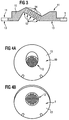
- a variant of a measuring tube 1 is shown schematically in FIG shown, the transmitter / receiver units 2, 3, wherein is either sounded in one direction or through the Use of combined transmitter / receiver units 2, 3 alternately in the opposite direction from left to right or right is sounded to the left through the medium flowing through.
- the course of the ultrasound signal 6 is through a family of lines indicated.
- the special guide reflectors 4, 5 serve for this purpose, those emitted by the transmitting / receiving units 2, 3 or received ultrasonic signals in a rough direction to lead. In between, approximately in the middle of the figure shown the ultrasonic signal 6 on a part of the inner wall of the Measuring tube 1, in this case reflected on the upper wall.
- FIG. 2 shows a streak image of an ultrasound beam, which is reflected solid / liquid at an interface.
- the beam dislocation 8 results from the splitting off of a Surface wave.
- the solid is below a drawn line and the fluid above located on this line.
- An incident beam also forms a surface normal 9 an angle of incidence 7, the reflected beam with the surface normal 9 an angle of reflection 71 forms.
- Figure 3 shows schematically as a sectional view in side view a special guide reflector 10 according to the invention as part of a measuring tube 1 with through the introduction of boreholes 12 the outer wall 13 of the reflector 10 implemented structuring.
- the boreholes 12 are perpendicular to that which they have drilled behind Measuring tube outer wall 13 introduced.
- the shape of the inner wall 11 of the reflector 1 remains unchanged.
- the cavities formed by the holes 12 are with Filling material 14 filled.
- FIG. 4a shows a reflector 10 in a view of its outer wall 13.
- the reflector 10 is through holes 12 that are marked here by a common arrow, from structured the outer wall 13 forth.
- the diameter of the boreholes 12 is 1 mm.
- FIG. 4b shows a reflector when looking at the outer wall 13 10 as in Figure 4a in supervision parallel to the course of the Boreholes 12 indicated by a common arrow are. You can recognize that by regular arrangement of the Boreholes 12 structuring.
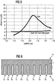
- Figure 5 shows by plotting the deviation of the measured Flow from a reference value in% against the Runtime of the ultrasound signal in ⁇ s the main impact the invention.
- the two graphs show that for one According to the invention, the flow-through numbers are drilled behind the reflector over a wide range of speeds of sound, which are converted here into terms of the ultrasound signal have been largely consistent during the deviation the flow measurements of a reflector a considerable one Dependence on the speed of sound shows.
- Figure 6 shows schematically as a sectional view in side view structuring the outer wall 13 of the measuring tube 1 with a Arrangement of saw cuts 15 that are perpendicular to the inner wall 11 of the measuring tube 1 are introduced and the one to the other have variable spacing.
Abstract
Description
Die Erfindung betrifft einen Durchflußmesser in Form eines von einem zu messenden Medium durchflossenen Meßrohres, wobei das Durchflußmedium mit Ultraschall beschallt wird und das ausgesandte Ultraschallsignal auf verschiedenen Wegen detektiert wird.The invention relates to a flow meter in the form of a measuring tube through which a medium to be measured flows the flow medium is sonicated with ultrasound and that emitted ultrasound signal detected in different ways becomes.
Das Prinzip der Wellenausbreitung von Ultraschall im bewegten Medium wird dazu benutzt, die Strömungsgeschwindigkeit v eines Mediums und damit das durch ein Rohr geflossene Volumen V zu messen. Es werden insbesondere Wellenpakete stromaufwärts und stromabwärts gesendet und empfangen und die jeweiligen Laufzeiten t↑ und t↓ bestimmt. Die Geschwindigkeit v ist zur Differenz der reziproken Laufzeiten (1/t↑-1/t↓) proportional.The principle of wave propagation of ultrasound in the moving medium is used to measure the flow velocity v of a medium and thus the volume V through a pipe. In particular, wave packets are sent and received upstream and downstream and the respective transit times t ↑ and t ↓ are determined. The speed v is proportional to the difference between the reciprocal running times (1 / t ↑ -1 / t ↓).
Bei der Durchflußmessung von Flüssigkeiten mittels Ultraschall
sind im allgemeinen zwei Verfahrensweisen möglich, um
vom Ultraschallsender zum Empfänger ausgesandte Wellenpakete
zu senden.
Die meisten auf dem Markt befindlichen Geräte benutzen das
Zwei- oder Mehrstrahlprinzip, bei dem sich die Wandler direkt
gegenüberstehen und die Wellenpakete direkt, d.h. ohne Reflexion
an den Innenwänden des Meßrohrs, durch das Medium gesendet
werden.
Gewisse Nachteile dieser Systeme können durch die Benutzung
von Reflexionen an den Innenwänden des Meßrohrs überwunden
werden. Die reflektierenden Bereiche des Meßrohrs können
durch spezielle Leitreflektoren realisiert sein.
Bei der Verwendung von Reflexionen zur Signalführung kann es
allerdings zu störenden Strahlversetzungen des Ultraschallsignals
kommen.When measuring the flow of liquids by means of ultrasound, two methods are generally possible in order to send wave packets sent from the ultrasound transmitter to the receiver.
Most devices on the market use the two-beam or multi-beam principle, in which the transducers face each other directly and the wave packets are sent directly through the medium, ie without reflection on the inner walls of the measuring tube.
Certain disadvantages of these systems can be overcome by using reflections on the inner walls of the measuring tube. The reflecting areas of the measuring tube can be realized by special guide reflectors.
When using reflections for signal routing, however, disruptive beam dislocations of the ultrasound signal can occur.
Bei der Benutzung von Reflexionen zur Signalführung innerhalb
des Meßrohrs hängen die Phase und die Amplitude einer reflektierten
Welle von den Materialeigenschaften des schallführenden
Mediums, des als Reflektor benutzten Materials und von
dem Winkel α zwischen der senkrechten auf den Reflektor und
dem einfallenden Schallsignal ab. Hierbei existieren verschiedene
Grenzwinkel, bei denen Wellenmoden-Umwandlungen
stattfinden. Man unterscheidet zwischen dem Grenzwinkel für
die Longitudinalwelle:
Hierbei steht I für die Flüssigkeit, II für den reflektierenden Festkörper, ν L bzw. ν T ist die Geschwindigkeit der Longitudinal- bzw. Transversalwelle im jeweiligen Material. Der Grenzwinkel für die Longitudinalwelle liegt im allgemeinen bei kleineren Winkeln, als der Grenzwinkel für die Transversalwelle. Ist der Einschallwinkel größer als α T,G' so herrscht totale Reflexion. α T,G' ist dann der sog. Grenzwinkel für Totalreflexion und der Reflexionskoeffizient wird zu 1.Here I stands for the liquid, II for the reflecting solid, ν L or ν T is the velocity of the longitudinal or transverse wave in the respective material. The critical angle for the longitudinal wave is generally smaller than the critical angle for the transverse wave. If the angle of incidence is greater than α T, G ' , there is total reflection. Then α T, G ' is the so-called critical angle for total reflection and the reflection coefficient becomes 1.
Bei Einfallswinkeln im Bereich des Grenzwinkels der Totalreflexion für die Transversalwelle spaltet die eingestrahlte Longitudinalwelle im Festkörper derart in eine Longitudinalwelle und eine Transversalwelle auf, daß diese zusammen mit der einfallenden Welle eine Oberflächenwelle, eine Rayleighwelle, bilden können. Die stärkste Oberflächenwelle entsteht bei einem Einfallswinkel etwas über dem Grenzwinkel. Bedingung für die Anregung ist, daß die sog. Spurwellenlänge der einfallenden Welle gleich der Wellenlänge der rayleighschen Oberflächenwelle ist. Die Geschwindigkeit der Oberflächenwelle hängt von den Longitudinal-und den Transversalwellen-Geschwindigkeiten im Reflektormaterial ab. Wegen der Reziprozität strahlt auch die entstehende Oberflächenwelle wieder eine Transversalwelle und eine Longitudinalwelle ab, die aber durch die Propagation der Rayleighwelle und der endlichen Breite der einfallenden Welle an einer anderen Stelle des Reflektors um einige Wellenlängen versetzt, wieder abgestrahlt wird.At angles of incidence in the area of the critical angle of total reflection for the transverse wave, the incident one splits Longitudinal wave in the solid state in this way into a longitudinal wave and a transverse wave that this together with the incident wave is a surface wave, a Rayleigh wave, can form. The strongest surface wave is created at an angle of incidence slightly above the critical angle. condition for the excitation is that the so-called incident wave equal to the wavelength of Rayleigh's Surface wave is. The speed of the surface wave depends on the longitudinal and transverse wave speeds in the reflector material. Because of the reciprocity radiates the resulting surface wave again a transverse wave and a longitudinal wave, but the through the propagation of the Rayleigh wave and the finite Width of the incident wave at another point on the reflector offset by a few wavelengths, emitted again becomes.
Ganz allgemein kann gesagt werden, daß bei der Reflexion von
Schallwellen ein Teil der reflektierten Schallwelle in den
reflektierenden Bereich des Meßrohrs eindringt, sich dort
ausbreitet und ortsversetzt teilweise als Störsignal wieder
in das Fluid abgestrahlt wird.
Dieses Eindringen wird erheblich verstärkt, wenn die oben erwähnte
Bedingung für das Auftreten starker Oberflächenwellen
im Material gleichzeitig für einen großen Flächenanteil des
reflektierenden Bereiches erfüllt ist.In general, it can be said that when sound waves are reflected, part of the reflected sound wave penetrates into the reflecting area of the measuring tube, spreads there and is partially radiated back into the fluid as an interference signal.
This penetration is considerably increased if the above-mentioned condition for the occurrence of strong surface waves in the material is simultaneously fulfilled for a large proportion of the reflecting area.
Die Strahlversetzung nimmt der an der vorgesehenen Stelle reflektierten Longitudinalwelle Energie weg und führt dort zu einem Pegelverlust. Dieser Pegelverlust und die gleichzeitige Erzeugung der ortsversetzten Welle führen zu zu einem Phasenverlauf, der einen starken ungünstigen Einfluß auf die Meßgenauigkeit hat, da er die Laufzeitdifferenzen, aus denen das durchflossenene Volumen errechnet wird, verfälscht.The beam displacement takes the one reflected at the intended location Longitudinal wave energy away and leads there a level loss. This level loss and the simultaneous Generation of the shifted wave lead to a phase curve, which has a strong unfavorable influence on the measuring accuracy because it has the maturity differences that make up the flowed through volume is calculated, falsified.
Das Auftreten der Strahlversetzung schränkt den Betriebsbereich für Ultraschalldurchflußmessungen bezüglich verschiedener Schallgeschwindigkeiten stark ein.The occurrence of beam dislocation limits the operating range for ultrasonic flow measurements regarding various Speeds of sound strongly.
Bisher sind Meßrohre für Ultraschalldurchflußmessungen bekannt, die einen relativ kleinen Betriebsbereich bezüglich verschiedener Schallgeschwindigkeiten in Medien aufweisen.So far, measuring tubes for ultrasonic flow measurements are known, which have a relatively small operating range have different sound velocities in media.
Aufgabe der Erfindung ist es, einen Durchflußmesser mit minimierter Baulänge bzw. erhöhtem Meßbereich bezüglich der Schallgeschwindigkeit in den Meßmedien oder mit erhöhter Meßgenauigkeit bereitzustellen. The object of the invention is to provide a flow meter with minimized Overall length or increased measuring range with respect to Speed of sound in the measuring media or with increased measuring accuracy to provide.
Die Lösung dieser Aufgabe geschieht durch die Merkmale des
Anspruches 1.This problem is solved by the features of
Der Erfindung liegt die Erkenntnis zugrunde, daß sich die
störende Strahlversetzung des Ultraschallsignals durch eine
Strukurierung des Außenwand, d.h. der nicht mit dem Medium in
Kontakt tretenden Wand, des Meßrohrs unterdrücken läßt.
Die Strukturierung reicht dazu so weit an die Innenwand des
Meßrohrs heran, daß sie die zur Ausbildung der Strahlversetzung
benötigten Raumbereiche erfaßte Die Innenwand des
Meßrohrs wird durch die Strukturierung nicht erfaßt, sie
bleibt also innerhalb einer bestimmten Wandstärke unstrukturiert.
Weil die Form der mit dem Medium in Kontakt tretenden
Innenwand des Meßrohrs durch die Strukturierung nicht verändert
wird, ergibt sich der Vorteil, daß das Meßrohr auch
nicht in seiner Funktion gestört wird.The invention is based on the knowledge that the disruptive beam displacement of the ultrasound signal can be suppressed by structuring the outer wall, ie the wall not in contact with the medium, of the measuring tube.
The structuring extends so far to the inner wall of the measuring tube that it covers the spatial areas required for the formation of the beam dislocation. The inner wall of the measuring tube is not covered by the structuring, so it remains unstructured within a certain wall thickness. Because the structure of the inner wall of the measuring tube coming into contact with the medium is not changed by the structuring, there is the advantage that the function of the measuring tube is not disturbed.
Für Rayleighwellen liegt beispielsweise die Eindringtiefe,
bei der die Amplitude des Signals auf einen Wert 1/e abgefallen
ist, bei einer Ultraschallfrequenz f = 2 MHZ in Edelstahl
bei ca. 1,25 mm.
Die Wandstärke kann beispielsweise in einem Bereich 0,25...2
Wellenlängen liegen, sie kann dabei an das Anforderungsprofil
des Meßrohres angepaßt sein. Beispielsweise kann bei einem
starken Effekt der Strahlversetzung die Strukturierung näher
an die Innenwand herangeführt werden als bei nur geringer Abspaltung
des Ultraschallsignals. Auch die Beschaffenheit des
Mediums kann die Dimensionierung der Wandstärke beeinflussen,
beispielsweise sollte bei abrasiver Wirkung des Mediums auf
das Meßrohr die Wandstärke hoch genug sein, damit keine Lecks
im Meßrohr auftreten.For Rayleigh waves, for example, the penetration depth, at which the amplitude of the signal has dropped to a
The wall thickness can be, for example, in a range of 0.25 ... 2 wavelengths, it can be adapted to the requirement profile of the measuring tube. For example, in the case of a strong effect of the beam dislocation, the structuring can be brought closer to the inner wall than with only a slight splitting off of the ultrasound signal. The nature of the medium can also influence the dimensioning of the wall thickness, for example if the medium has an abrasive effect on the measuring tube, the wall thickness should be high enough so that no leaks occur in the measuring tube.
Die Strukturierung kann beispielsweise dadurch erfolgen, daß Bohrungen, beispielsweise Sacklochbohrungen, oder Schnitte, beispielsweise Sägeschnitte oder Fräsungen, in die Außenwand des Meßrohrs eingebracht werden. Bohrungen und Schnitte besitzen gegenüber einer großflächigen Materialabtragung den Vorteil, daß die Stabilität des Meßrohrs weitgehend erhalten bleibt.The structuring can take place, for example, in that Bores, for example blind holes, or cuts, for example saw cuts or millings, in the outer wall of the measuring tube. Have holes and cuts compared to a large-scale material removal Advantage that the stability of the measuring tube is largely preserved remains.
Prinzipiell können die Bohrloch- bzw. Schnittmuster in beliebiger Weise auf die Form des jeweiligen Meßrohrs abgestimmt sein, beispielsweise in bezug auf Muster, Durchmesser, Tiefe und Richtung der Bohrungen oder Richtung, Breite und Tiefe der Schnitte.In principle, the borehole or cutting pattern can be in any Matched to the shape of the respective measuring tube be, for example, in terms of pattern, diameter, depth and direction of the holes or direction, width and depth the cuts.
Zur Verhinderung der Ausbreitung störender Ultraschallwellen
im Meßrohr erfolgt die Strukturierung vorteilhafterweise dadurch,
daß die einzelnen Bestandteile der Strukturierung,
beispielsweise einzelne Bohrungen oder Schnitte, im Abstand
einiger Wellenlängenbruchteile der störenden Schallwelle im
Meßrohr voneinander eingebracht sind. Dadurch wird schon am
Ort des Auftreffens einer Ultraschallwelle auf das Meßrohr
deren Ausbreitung im Meßrohr unterdrückt.
Dabei ist es vorteilhaft, wenn das Strukturierungsmuster regelmäßig
ist, beispielsweise durch regelmäßige Anordnung von
Bohrungen oder Schnitten.To prevent the propagation of disruptive ultrasonic waves in the measuring tube, the structuring is advantageously carried out by introducing the individual components of the structuring, for example individual bores or cuts, at a distance of a few wavelength fractions of the interfering sound wave in the measuring tube. As a result, the propagation of an ultrasonic wave on the measuring tube is suppressed from the point at which it hits the measuring tube.
It is advantageous if the structuring pattern is regular, for example by regularly arranging bores or cuts.
Andererseits kann die Strahlversetzung auch dadurch unterdrückt werden, daß zwar die Ausbreitung der Ultraschallwellen im Meßrohr erlaubt wird, aber deren Ausbreitungsgeschwindigkeit über den gesamten reflektierenden Bereich hinweg durch eine Strukturierung moduliert wird. Diese Modulation bewirkt, daß die störende Strahlversetzung über die Fläche des reflektierenden Bereichs hinweg weitgehend ausgelöscht wird. Bei dieser Art der Unterdrückung der störenden Strahlversetzung besitzen die einzelnen Bestandteile der Strukturierung vorteilhafterweise einen variierenden Abstand mit zueinander. Die Abstände können dabei auch irregulär sein.On the other hand, this can also suppress beam dislocation be that while the propagation of the ultrasonic waves is allowed in the measuring tube, but their speed of propagation across the entire reflective area a structuring is modulated. This modulation causes that the disruptive beam displacement across the surface of the reflective Area is largely wiped out. At this type of suppression of the disruptive beam dislocation own the individual components of the structuring advantageously a varying distance with each other. The distances can also be irregular.
Bei der Strukturierung ist es vorteilhaft, wenn die einzelnen Bestandteile der Strukturierung die gleichen Maße besitzen, beispielsweise wenn die einzelnen Bohrungen eines Bohrlochmusters die gleiche Tiefe und/oder den gleichen Durchmesser aufweisen, bzw. die einzelnen Schnitte eines Schnittmusters die gleiche Tiefe und/oder die gleiche Breite aufweisen.When structuring, it is advantageous if the individual Components of the structuring have the same dimensions, for example if the individual holes of a borehole pattern the same depth and / or the same diameter have, or the individual cuts of a pattern have the same depth and / or the same width.
Auch geeignet, insbesondere bei Meßrohren mit geringer Wandstärke, ist die Strukturierung durch Walzen, Rändeln, Prägen oder vergleichbare Bearbeitungsschritte.Also suitable, especially for measuring tubes with thin walls, is the structuring by rolling, knurling, embossing or comparable processing steps.
Eine beliebige Kombination dieser Strukturierungsmaßnahmen ist im Sinne der Erfindung ebenfalls denkbar.Any combination of these structuring measures is also conceivable in the sense of the invention.
Weiterhin ist es vorteilhaft, wenn die Strukturierung so angeordnet ist, daß das auf die Innenwand des Meßrohrs projizierte Muster der Strukturierung mit der Form der auf das Meßrohr auftreffenden Wellenfronten des Ultraschallsignals möglichst übereinstimmt. Gegebenenfalls kann auch ein zusätzlicher Winkelversatz zwischen dem projizierten Muster und der Wellenfront auftreten.It is also advantageous if the structuring is arranged in this way is that that is projected onto the inner wall of the measuring tube Pattern of structuring with the shape of the on the Measuring tube impinging wave fronts of the ultrasonic signal matches as much as possible. If necessary, an additional one Angular misalignment between the projected pattern and the Wavefront occur.
Durch die Strukturierung entstandene Hohlräume des Meßrohrs können mit vom Wandmaterial verschiedem Material ausgefüllt sein. Dabei ist es vorteilhaft, wenn das Füllmaterial eine hohe Dämpfungskonstante für akustische Wellen besitzt.Cavities in the measuring tube created by the structuring can be filled with material different from the wall material be. It is advantageous if the filling material is a has a high damping constant for acoustic waves.
Weiterhin kann durch die Aufbringung einer Abdeckung auf die Strukturierung die Strukturierung geschützt werden. Beispielsweise kann eine Deckplatte auf die Strukturierung gelegt werden, beispielsweise durch Aufschweißen einer Metallplatte, die mit der Außenwand des Meßrohrs beispielsweise bündig abschließt. Dadurch kann die Strukturierung vor mechanischen oder chemischen Einflüssen der Umgebung des Meßrohrs geschützt werden.Furthermore, by applying a cover to the Structuring the structuring to be protected. For example a cover plate can be placed on the structure are, for example by welding a metal plate, with the outer wall of the measuring tube, for example ends flush. This can structure the mechanical or chemical influences in the vicinity of the measuring tube to be protected.
Zur Wegoptimierung des Ultraschallsignals in dem zu messenden Fluid ist es vorteilhaft, wenn die reflektierenden Bereiche des Meßrohrs durch spezielle Leitreflektoren realisiert sind. For path optimization of the ultrasonic signal in the one to be measured Fluid it is advantageous if the reflective areas of the measuring tube are realized by special guide reflectors.
In den folgenden Figuren wird die Erfindung anhand von Ausführungsbeispielen
dargestellt.
In Figur 1 wird eine Variante eines Meßrohres 1 schematisch
dargestellt, die Sende-/Empfangseinheiten 2, 3 aufweist, wobei
entweder in einer Richtung geschallt wird oder durch den
Einsatz von kombinierten Sende-/Empfangseinheiten 2, 3 abwechselnd
in Gegenrichtung von links nach rechts bzw. rechts
nach links durch das hindurchfließende Medium geschallt wird.
Der Verlauf des Ultraschallsignales 6 ist durch eine Linienschar
angedeutet. Die speziellen Leitreflektoren 4, 5 dienen
dazu, die von den Sende-/Empfangseinheiten 2, 3 ausgesandten
bzw. empfangenen Ultraschallsignale in eine grobe Richtung zu
führen. Dazwischen, etwa in der Mitte der dargestellten Figur
wird das Ultraschallsignal 6 an einem Teil der Innenwand des
Meßrohrs 1, in diesem Fall an der oberen Wand, reflektiert.A variant of a measuring
Figur 2 zeigt eine Schlierenaufnahme eines Ultraschallstrahles,
der an einer Grenzfläche fest/flüssig reflektiert wird.
Die Strahlversetzung 8 ergibt sich durch die Abspaltung einer
Oberflächenwelle. In Figur 2 ist dabei der Festkörper unterhalb
einer eingezeichneten Grenzlinie und das Fluid oberhalb
dieser Linie angesiedelt. Ein einfallender Strahl bildet mit
einer Flächennormalen 9 einen Einfallswinkel 7, wobei der
reflektierte Strahl mit der Flächennormalen 9 einen Reflexionswinkel
71 bildet.FIG. 2 shows a streak image of an ultrasound beam,
which is reflected solid / liquid at an interface.
The
Figur 3 zeigt schematisch als Schnittbild in Seitenansicht
einen erfindungsgemäßen speziellen Leitreflektor 10 als Teil
eines Meßrohrs 1 mit durch Einbringung von Bohrlöchern 12 an
der Außenwand 13 des Reflektors 10 realisierter Strukturierung.
Die Bohrlöcher 12 sind senkrecht zu der von ihnen hinterbohrten
Meßrohraußenwand 13 eingebracht. Die Form der Innenwand
11 des Reflektors 1 bleibt dadurch unverändert. Die
durch die Bohrungen 12 entstandenen Hohlräume sind mit
Füllmaterial 14 gefüllt.Figure 3 shows schematically as a sectional view in side view
a
Figur 4a zeigt einen Reflektor 10 in Aufsicht auf dessen Außenwand
13. Der Reflektor 10 ist durch Bohrlöcher 12, die
hier durch einen gemeinsamen Pfeil gekennzeichnet sind, von
der Außenwand 13 her strukturiert. Der Durchmesser der Bohrlöcher
12 beträgt 1 mm.FIG. 4a shows a
Figur 4b zeigt in Betrachtung der Außenwand 13 einen Reflektor
10 wie in Figur 4a in Aufsicht parallel zum Verlauf der
Bohrlöcher 12, die durch einen gemeinsamen Pfeil gekennzeichnet
sind. Man erkennt die durch regelmäßige Anordnung der
Bohrlöcher 12 entstandene Strukturierung.FIG. 4b shows a reflector when looking at the
Figur 5 zeigt durch eine Auftragung der Abweichung des gemessenen Durchflusses von einem Referenzwert in % gegen die Laufzeit des Ultraschallsignals in µs die wesentliche Auswirkung der Erfindung. Die beiden Graphen zeigen, daß für einen erfindungsgemäß hinterbohrten Reflektor die Durchflußmeßzahlen über einen breiten Bereich von Schallgeschwindigkeiten, die hier in Laufzeiten des Ultraschallsignals umgerechnet wurden, weitgehend gleichbleibend sind, während die Abweichung der Durchflußmeßzahlen eines Reflektors eine beträchtliche Abhängigkeit von der Schallgeschwindigkeit zeigt. Figure 5 shows by plotting the deviation of the measured Flow from a reference value in% against the Runtime of the ultrasound signal in µs the main impact the invention. The two graphs show that for one According to the invention, the flow-through numbers are drilled behind the reflector over a wide range of speeds of sound, which are converted here into terms of the ultrasound signal have been largely consistent during the deviation the flow measurements of a reflector a considerable one Dependence on the speed of sound shows.
Die Wirksamkeit des Vorgehens im erfinderischen Sinne kann somit dokumentiert werden. Für das Experiment wurde eine konstante Strömungsgeschwindigkeit eingestellt. Die Variation der Schallgeschwindigkeit c erfolgte durch Erwärmen des Mediums.The effectiveness of the procedure in the inventive sense can thus be documented. For the experiment, a constant Flow rate set. The variation the speed of sound c was achieved by heating the medium.
Figur 6 zeigt schematisch als Schnittbild in Seitenansicht
eine Strukturierung der Außenwand 13 des Meßrohrs 1 mit einer
Anordnung von Sägeschnitten 15, die senkrecht zur Innenwand
11 des Meßrohrs 1 eingebracht sind und die zueinander einen
variablen Abstand besitzen.Figure 6 shows schematically as a sectional view in side view
structuring the
Claims (9)
wobei ein das Ultraschallsignal (6) reflektierender Bereich des Meßrohrs (1) von seiner Außenwand (13) her so strukturiert ist, daß
wherein an area of the measuring tube (1) reflecting the ultrasonic signal (6) is structured from its outer wall (13) in such a way that
Applications Claiming Priority (2)
| Application Number | Priority Date | Filing Date | Title |
|---|---|---|---|
| DE1997155152 DE19755152C1 (en) | 1997-12-11 | 1997-12-11 | Ultrasonic flow gauge |
| DE19755152 | 1997-12-11 |
Publications (2)
| Publication Number | Publication Date |
|---|---|
| EP0922937A2 true EP0922937A2 (en) | 1999-06-16 |
| EP0922937A3 EP0922937A3 (en) | 2000-07-05 |
Family
ID=7851618
Family Applications (1)
| Application Number | Title | Priority Date | Filing Date |
|---|---|---|---|
| EP98122721A Withdrawn EP0922937A3 (en) | 1997-12-11 | 1998-11-30 | Ultrasonic flow metering tube |
Country Status (2)
| Country | Link |
|---|---|
| EP (1) | EP0922937A3 (en) |
| DE (1) | DE19755152C1 (en) |
Cited By (1)
| Publication number | Priority date | Publication date | Assignee | Title |
|---|---|---|---|---|
| DE102018133066A1 (en) * | 2018-12-20 | 2020-06-25 | Endress+Hauser Flowtec Ag | Ultrasonic measuring device |
Citations (2)
| Publication number | Priority date | Publication date | Assignee | Title |
|---|---|---|---|---|
| EP0212470A2 (en) * | 1985-08-12 | 1987-03-04 | Panametrics, Inc. | Apparatus for measuring fluid characteristics using surface generated volumetric interrogation signals |
| DE3911408A1 (en) * | 1989-04-07 | 1990-10-11 | Siemens Ag | Measuring tube for ultrasonic flow measurements |
Family Cites Families (1)
| Publication number | Priority date | Publication date | Assignee | Title |
|---|---|---|---|---|
| DE4336370C1 (en) * | 1993-10-25 | 1995-02-02 | Siemens Ag | Device for flow measurement |
-
1997
- 1997-12-11 DE DE1997155152 patent/DE19755152C1/en not_active Expired - Fee Related
-
1998
- 1998-11-30 EP EP98122721A patent/EP0922937A3/en not_active Withdrawn
Patent Citations (2)
| Publication number | Priority date | Publication date | Assignee | Title |
|---|---|---|---|---|
| EP0212470A2 (en) * | 1985-08-12 | 1987-03-04 | Panametrics, Inc. | Apparatus for measuring fluid characteristics using surface generated volumetric interrogation signals |
| DE3911408A1 (en) * | 1989-04-07 | 1990-10-11 | Siemens Ag | Measuring tube for ultrasonic flow measurements |
Cited By (2)
| Publication number | Priority date | Publication date | Assignee | Title |
|---|---|---|---|---|
| DE102018133066A1 (en) * | 2018-12-20 | 2020-06-25 | Endress+Hauser Flowtec Ag | Ultrasonic measuring device |
| CN113242959A (en) * | 2018-12-20 | 2021-08-10 | 恩德斯+豪斯流量技术股份有限公司 | Ultrasonic instrument |
Also Published As
| Publication number | Publication date |
|---|---|
| EP0922937A3 (en) | 2000-07-05 |
| DE19755152C1 (en) | 1999-05-06 |
Similar Documents
| Publication | Publication Date | Title |
|---|---|---|
| DE4430223A1 (en) | Ultrasonic flow measuring method and device for carrying out the method | |
| DE4010148A1 (en) | IMPROVEMENT FOR AN ULTRASONIC GAS / LIQUID FLOW METER | |
| EP2440888B1 (en) | Method for measuring a measurement variable | |
| DE19722274A1 (en) | Method for measuring density and mass flow | |
| DE1958235A1 (en) | Method and device for measuring currents in lines | |
| EP1716394A2 (en) | Ultrasonic flow sensor comprising staggered transmitting and receiving elements | |
| EP3577427A1 (en) | Ultrasonic meter and method for sensing a flow variable | |
| DE102014115203B3 (en) | Method and arrangement for ultrasonic clamp-on flow measurement and circuit arrangement for controlling an ultrasonic clamp-on flow measurement | |
| EP1955019B1 (en) | Ultrasonic measuring apparatus for determining and/or monitoring the volume or mass flow rate of a medium through a pipe | |
| WO2012084391A1 (en) | Coupling element of an ultrasonic transducer for an ultrasonic flow meter | |
| DE19944047C2 (en) | Device for measuring concentration or density as well as particles | |
| DE102009046159A1 (en) | Ultrasonic flow and particle measuring system | |
| DE102010063789A1 (en) | Ultrasonic flowmeter | |
| EP3867636B1 (en) | Method and device for non-invasive determination of multi-phase current properties | |
| DE2656857C2 (en) | Transducer for ship ultrasonic Doppler navigation systems | |
| DE19934212B4 (en) | Method and device for measuring the flow rate of a fluid stream | |
| EP0922937A2 (en) | Ultrasonic flow metering tube | |
| DE102011115691A1 (en) | Method for determination of viscosity of mineral oil, involves computing viscosity based on amplitude and frequency of ultrasonic signals and time period required for ultrasonic waves for passing through measuring section | |
| DE3911408A1 (en) | Measuring tube for ultrasonic flow measurements | |
| DE3241815A1 (en) | NON-DESTRUCTIVE ULTRASONIC TEST DEVICE | |
| DE3013482A1 (en) | Ultrasonic head for Doppler flow measurement - has piezoelectric vibrator half-wave plate and low temp. coefficient path | |
| DE102015106695A1 (en) | Method and device for flow measurement | |
| DE102016116070A1 (en) | Vortex flowmeter foreign body detection method, vortex flowmeter, vortex flowmeter assembly, and single-position bottling system | |
| DE102011004830B4 (en) | Phase method for measuring the propagation velocity of sound waves with dynamic measurement window | |
| EP3855134A1 (en) | Device for measuring the flow speed of a fluid |
Legal Events
| Date | Code | Title | Description |
|---|---|---|---|
| PUAI | Public reference made under article 153(3) epc to a published international application that has entered the european phase |
Free format text: ORIGINAL CODE: 0009012 |
|
| AK | Designated contracting states |
Kind code of ref document: A2 Designated state(s): CH DE DK GB LI NL |
|
| AX | Request for extension of the european patent |
Free format text: AL;LT;LV;MK;RO;SI |
|
| PUAL | Search report despatched |
Free format text: ORIGINAL CODE: 0009013 |
|
| AK | Designated contracting states |
Kind code of ref document: A3 Designated state(s): AT BE CH CY DE DK ES FI FR GB GR IE IT LI LU MC NL PT SE |
|
| AX | Request for extension of the european patent |
Free format text: AL;LT;LV;MK;RO;SI |
|
| 17P | Request for examination filed |
Effective date: 20001106 |
|
| AKX | Designation fees paid | ||
| RBV | Designated contracting states (corrected) |
Designated state(s): CH DE DK GB LI NL |
|
| REG | Reference to a national code |
Ref country code: DE Ref legal event code: 8566 |
|
| 17Q | First examination report despatched |
Effective date: 20070413 |
|
| STAA | Information on the status of an ep patent application or granted ep patent |
Free format text: STATUS: THE APPLICATION IS DEEMED TO BE WITHDRAWN |
|
| 18D | Application deemed to be withdrawn |
Effective date: 20070601 |