EP0922580A2 - Farbkontrollsystem für eine Druckmaschine - Google Patents
Farbkontrollsystem für eine Druckmaschine Download PDFInfo
- Publication number
- EP0922580A2 EP0922580A2 EP98309181A EP98309181A EP0922580A2 EP 0922580 A2 EP0922580 A2 EP 0922580A2 EP 98309181 A EP98309181 A EP 98309181A EP 98309181 A EP98309181 A EP 98309181A EP 0922580 A2 EP0922580 A2 EP 0922580A2
- Authority
- EP
- European Patent Office
- Prior art keywords
- ink
- controller
- adaptive
- sid
- tuner
- Prior art date
- Legal status (The legal status is an assumption and is not a legal conclusion. Google has not performed a legal analysis and makes no representation as to the accuracy of the status listed.)
- Withdrawn
Links
Images


Classifications
-
- B—PERFORMING OPERATIONS; TRANSPORTING
- B41—PRINTING; LINING MACHINES; TYPEWRITERS; STAMPS
- B41F—PRINTING MACHINES OR PRESSES
- B41F33/00—Indicating, counting, warning, control or safety devices
- B41F33/0027—Devices for scanning originals, printing formes or the like for determining or presetting the ink supply
-
- B—PERFORMING OPERATIONS; TRANSPORTING
- B41—PRINTING; LINING MACHINES; TYPEWRITERS; STAMPS
- B41F—PRINTING MACHINES OR PRESSES
- B41F33/00—Indicating, counting, warning, control or safety devices
- B41F33/0036—Devices for scanning or checking the printed matter for quality control
- B41F33/0045—Devices for scanning or checking the printed matter for quality control for automatically regulating the ink supply
-
- B—PERFORMING OPERATIONS; TRANSPORTING
- B41—PRINTING; LINING MACHINES; TYPEWRITERS; STAMPS
- B41P—INDEXING SCHEME RELATING TO PRINTING, LINING MACHINES, TYPEWRITERS, AND TO STAMPS
- B41P2233/00—Arrangements for the operation of printing presses
- B41P2233/10—Starting-up the machine
- B41P2233/11—Pre-inking
Definitions
- the present invention relates generally to a system and method for controlling the ink feed in a web-offset printing press in order to achieve and maintain target values of color. More particularly, the invention relates to a system for controlling the ink feed using a fuzzy logic adaptive closed loop controller.
- a web-offset printing press operates to print a multi-color image by combining several single color images through superimposed printing on a moving substrate or web.
- a typical four color printing process includes black, cyan, magenta and yellow ink.
- the color quality of the printed image is determined by the degree to which the colors of the printed image match a desired or exemplary reference image, which is often provided or endorsed by the print customer.
- One way to evaluate color involves visual examination of the printed image by a trained pressman.
- Another way to evaluate color is to measure the optical density of a solid color bar printed on the substrate. In general terms, the actual color quality is compared to the desired quality, and the amount of ink fed to the substrate is adjusted as necessary.
- the printing press includes an inking assembly for each color of ink used in the printing process.
- Each inking assembly includes an ink reservoir as well as a blade disposed along the outer surface of an ink fountain roller.
- the amount of ink supplied to the roller train of the press and ultimately to a substrate such as paper is adjusted by changing the spacing between the edge of the blade and the outer surface of the ink fountain roller.
- the blade is divided into a plurality of blade segments, and the position of each blade segment relative to the ink fountain roller is independently adjustable by movement of an adjusting screw, or ink key, to thereby control the amount of ink fed to a corresponding strip or zone of the substrate extending in the longitudinal direction.
- a typical printing press includes 24-30 ink keys which operate to control ink to an ink key zone having a dimension of approximately 1.2-2.5 inches.
- Ink is also spread laterally from one ink key zone to adjacent zones on the substrate due to the movement of vibrator rollers, which oscillate in a lateral direction relative to the longitudinal direction of travel of the substrate.
- ink keys In order to preset the initial positions of the ink keys, it is common for a printing press operator to visually examine printed copies or proofs of the image to be printed and to note the amount of color necessary in respective zones of the image to be printed. Based on this visual examination as well as experience with the press, ink, and type of substrate (typically paper), the operator may preset the ink keys to approximate the settings that will be required once the press is running.
- low-tack yellow ink has a low pigment strength and requires a greater amount of ink to produce an image with a given optical density.
- uncoated paper requires more ink than does coated paper to achieve an image having a given optical density.
- the rate of ink flow from the ink fountain to the web must be controlled by adjusting the ink keys for each of the ink colors.
- the time spent for the ink key adjustment until the desired solid ink density for each zone is achieved on press is termed makeready.
- ink key adjustment is typically achieved based on visual examination and manual adjustment by an experienced press operator.
- makeready it is common for a press operator to continually monitor the printed output and to make appropriate ink key adjustments in order to achieve appropriate quality control of the color of the printed image. For example, if the color in a zone is too weak, the operator adjusts the corresponding ink key to allow more ink flow to that zone; if the color is too strong, the corresponding ink key is adjusted to decrease the ink flow. Also during runtime, further color adjustments may be necessary to compensate for changing press conditions, or to account for the personal preferences of the customer.
- Optical density of various points of a printed image can be measured by using a densitometer or scanning densitometer either off-line or on-line of the web printing process. Optical density measurements are performed by illuminating a test image with a light source and measuring the intensity of the light reflected from the image.
- start-up waste can be a major percentage of total time and materials required.
- a conventional proportional-integral-derivative (PID) controller is the most widely used controller in industry.
- the conventional PID controller was developed in the 1940's based on the classical linear time-invariant system. Theoretically, such a controller would work well in a printing application to control ink feed rate provided that the entire printing process was linear and time invariant. In other words, the color density would need to be proportional to the ink key settings and the factors affecting the entire printing process would need to remain unchanged.
- a conventional PID controller does not work well if the controlled system is highly nonlinear or includes uncertain factors in the working environment. Because web offset printing is a very complicated process, there are many known and unknown factors which affect the measured solid ink density (SID) values such that the overall system is nonlinear. Known factors affecting the SID values include the make and model of the printing press, ink and color variations, fountain solution pH value, operating temperature variations, differences in paper stock, age and speed of the press, etc. Consequently, it is not desirable to control color using a PID controller alone having a fixed set of PID parameters because such a controller is unable to account for all the different operating conditions.
- SID solid ink density
- adaptive control With adaptive control, the gain parameters Kp, Ki, and Kd of a PID controller are tuned to "optimal" values in real time.
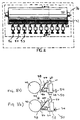
- Fig. 1 illustrates a web-offset printing system 10 for printing a multi-color image upon a moving web 12.
- four printing units 14, 16, 18, and 20 each print one color of the image upon the web 12.
- the location of printing units 14, 16, 18, and 20 relative to each other is determined by the printer, and may vary.
- Each printing unit 14, 16, 18, 20 includes a printing plate cylinder and a blanket cylinder. This type of printing is commonly referred to as web-offset printing.
- each printing unit includes an upper blanket cylinder 22, an upper printing plate cylinder 24, a lower blanket cylinder 26, and a lower printing plate cylinder 28 to permit printing on both sides of web 12.
- colors 31, 32, 33, and 34 on printing units 14, 16, 18, and 20, respectively are typically black (K), cyan (C), magenta (M), and yellow (Y).
- Cyan, magenta, and yellow are three subtractive primary color inks which are used to reproduce the color image.
- the black ink is used to sharpen features and to replace the overprints of the three primary ink colors.
- Each printing unit 14, 16, 18, and 20 includes an associated inking assembly 36 which is shown in Fig. 2.
- Inking assembly 36 operates to supply ink to a roller train which includes a plate cylinder and a blanket cylinder and then to the web 12.
- inking assembly 36 includes an ink reservoir 38 disposed adjacent an ink fountain roller 40 (also known as the ink ball) which extends laterally across the web.
- a blade 42 extends along the ink fountain roller 40 and is segmented so that the spacing of each segment relative to the ink fountain roller 40 can be independently adjusted to control the ink fed to a respective ink key zone on the web 12.
- each blade segment 44 has an edge 46 which is moved toward and away from the outer surface 48 of the ink fountain roller 40 by adjustment of an associated ink flow adjustment device 50.
- a portion of the ink fountain roller 40 forms one main wall of the ink reservoir 38.
- the other principal wall of the reservoir 38 is provided by the blade segments 44.
- Ink passes from the ink reservoir 38 through the space between the surface of the ink fountain roller 40 and the lower edge 46 of the blade segment 44, and the spacing of the blade edge 46 to the ink fountain roller 40 acts to control the thickness of the ink film provided to the outer surface 48 of ink fountain roller 40.
- a plurality of the ink flow adjustment devices 50 are disposed at equally-spaced lateral locations along the inking assembly 36 to press against the blade segments 44 at those locations to establish and adjust the size of the space between the roller 40 and the blade segment 44.
- Each ink flow adjustment device 50 includes an ink key 54 having screw threads engaging threads in a fixed portion of the frame of the inking assembly 36.
- the ink key 54 has a tip portion 56 which pushes against the associated blade segment 44 to deflect it and to thereby provide locally adjustable control of the spacing and the ink feed.
- the ink key 54 is driven by a bi-directional actuator motor 58 which operates to move the ink key 54 toward and away from the ink fountain roller 40.
- a potentiometer 60 has a movable arm mechanically connected with the ink key 54.
- the potentiometer 60 has a pair of outside electrical terminals and an inside electrical terminal located between the outside electrical terminals.
- the inside terminal of the potentiometer is mechanically connected to the movable arm of the potentiometer 60.
- the position of the movable arm of the potentiometer 60 depends upon the position of the ink key 54.
- the potentiometer 60 is energized at its outside electrical terminals so that an electrical signal indicative of the position of the ink key is produced at the inside electrical terminal of the potentiometer.
- the motor 58 is responsive to a signal on line 66 to position the ink key 54 as desired.
- Fig. 4 is an illustration of a side view of a roller train 96 of a lower printing unit of a Harris M1000B printing press.
- Ink is supplied from the inking assembly 36 via the ink fountain roller 40 to a ductor roller 98 which continuously moves back and forth from contact with the ink fountain roller 40 and roller 100.
- the amount of ink on the ink fountain roller itself is also adjustable by changing the angle that the ink fountain roller 40 rotates each stroke. This occurs by adjusting a conventional ratchet assembly (not shown) as is known in the art.
- the rotation angle along with the positions of the blade segments 44, determine the amount of ink transferred to the ductor roller 98.
- the relationship between the rotation angle and the amount of ink transferred to ductor roller 98 is assumed to be linear.
- Ink is supplied from roller 100 to the various other rollers 102-124 as shown in Fig. 4.
- the arrows of Fig. 4 indicate the direction of rotation of rollers 98-124.
- Rollers 100, 104, 114, and 118 are vibrator rollers which oscillate back and forth in a lateral direction with respect to the longitudinal direction of travel of the web 12, thereby operating to spread ink from one ink key zone to adjacent ink key zones.
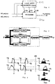
- the control system 200 operates to adjust the position of the ink keys 54 to control the position of the blade segments 44 in order to control the amount of ink fed to corresponding ink key zones on the web 12 of the printing press.
- the control system 200 includes controller 204 and a color density measuring system 208.
- the color density measuring system 208 generates measured solid ink density (SID) values for color bar patches in a color bar oriented transversely across the web 12.
- the controller 204 operates to maintain the SID values for each color patch within a desired range.
- the measured SID values are called the controlled variables, and are the ultimate control target of the controller 204.
- the controller 204 includes a fuzzy logic parameter tuner 212, a conventional Proportional-Integral-Differential (PID) controller 216, and optionally, a decoupling computation unit 220.
- the fuzzy logic parameter tuner 212 adaptively adjusts gain parameters in the PID controller 216.
- the PID controller 216 provides signals to the decoupling computation unit 220.
- the decoupling computation unit 220 takes into account the effects of the ink key coupling due to the lateral movement of the vibrator rollers 100, 104, 114 and 118 and provides signals to drive the motors 58 to independently control the position of each ink key 54. In operation without the decoupling computation unit 220, the signals from the PID controller 216 are directly provided to the ink keys 54.
- controller 204 can also interface with a ratchet assembly 224 to control the angle of rotation of the ink fountain roller 40.
- the color density measuring system 208 includes a color CCD video camera mounted on a transport bar that spans across the web.
- the system 208 reports values of solid ink density of solid color patches within a color bar that is oriented transversely across the web 12.
- a strobe light is flashed at an appropriate time so that the color CCD camera obtains an image of a portion of the color bar on the web 12.
- the image of the color bar is processed through an algorithm to calculate an accurate SID value for each individual color patch. These SID values are fed to the controller 204.
- the camera is moved laterally across the web 12 in a series of steps to acquire sequential images in all the ink key zones across the web 12.
- a color density measuring system 208 which accurately measures the optical density of a printed image while the press is running is the color measuring system (CMS) described in U.S. Pat. App. Serial No. 08/434,928, invented by John C. Seymour, Jeffrey P. Rappette, Frank N. Vroman, Chia-Lin Chu, Bradly S. Moersfelder, Michael A. Gill and Karl R. Voss, entitled "SYSTEM AND METHOD FOR MONITORING COLOR IN A PRINTING PRESS", which is hereby incorporated by reference.
- CMS color measuring system
- Fig. 6 illustrates the relationship between the PID controller 216 and the fuzzy logic parameter tuner 212.
- the two calculated signals, SID_err(j,k,t) (or the SID error signal for color j and ink key k at time t) and SID_derr(j,k,t) (or the change in the SID error signal for color j and ink key k at time t) are fed both to the fuzzy logic parameter tuner 212 and the PID controller 216.
- the PID controller 216 computes the ink key settings to achieve the desired set point SID values for each ink key zone and for each ink color, without accounting for the coupling of the ink keys.
- the function of the fuzzy logic parameter tuner 212 is to adjust the three gain parameters in the PID controller 216 adaptively to compensate for the variations in press performance.
- the second method is preferred because it is more stable and reduces drastic swings in parameter values over time.
- the overall output of the PID controller 216 is the unadjusted command ink key setting. Since the color density measuring system 208 reports the SID values sequentially, the PID controller 216 can be implemented sequentially.
- the parameters Kp, Ki, and Kd of the PID controller 216 are tuned to some "optimal" value in real time.
- One way to accomplish adaptive control is utilizing fuzzy logic.
- Fuzzy logic is based on fuzzy set theory and operates to map an input space to an output space.
- fuzzy logic incorporates the operation knowledge of human experts into a control loop. Fuzzy logic is also useful for modelling nonlinear functions of arbitrary complexity. Fuzzy logic can be blended with conventional control techniques, such as conventional PID control.
- the embodiment described herein is an example of an indirect fuzzy logic control system.
- An indirect fuzzy logic control system is used in conjunction with, for example, a conventional PID controller and has the advantage that the control design is separated from the adaptive mechanism.
- a direct fuzzy logic controller generally uses a static incremental process model to relate the error in the calculated control action to the deviation in the desired behavior.
- Fuzzy logic includes the concept of fuzzy sets.
- a fuzzy set is one that does not have clear and crisp boundaries but instead describes a somewhat vague concept. Examples of fuzzy sets are:
- a membership function is a curve that defines how each point in the input space is mapped to a membership value (or degree of membership), which is a value between 0 and 1.
- a man of age 69 may belong to the fuzzy set of "old people" with a membership value of .8 (the degree of belonging to the set).
- a membership function can be represented by curves of various shapes including, for example, triangular, gaussian, bell shaped, sigmoidal, and polynomial-based curves, as well as others.
- fuzzy sets do not obey the rule of "mutually exclusive."
- An item can belong to two or more different fuzzy sets simultaneously.
- a man of age 69 could belong to the fuzzy set "young people” with a membership function value of only .2 at the same time he belongs to the fuzzy set "old people” with a membership function value of .8.
- a fuzzy inference system such as that depicted in Fig. 7, is capable of implementing a nonlinear mapping from its input space to an output space.
- the mapping is accomplished by a number of fuzzy if-then rules, each of which describes the local behavior of the mapping and which reflects certain knowledge of human experts' decision making process.
- fuzzy if-then rules each of which describes the local behavior of the mapping and which reflects certain knowledge of human experts' decision making process.
- the following rules are an example of a method for determining the size of a tip at a restaurant:
- the rules establish a simple input-output inference system, where "food quality” and “service quality” are the input fuzzy variables, and the single output fuzzy variable is "the amount of the tip".
- the antecedent of a rule defines a fuzzy region in the input space, while the consequent specifies a fuzzy region in the output space.
- a fuzzy inference system basically includes the functions of fuzzification, inferencing, aggregation, and defuzzification.
- One way to accomplish the above steps is known as the Mamdani fuzzy inference system, which is known in the art.
- the Mamdani inference system includes output membership functions (shown as C1 and C2) which are also fuzzy sets.
- the inputs to the fuzzy inference system are common crisp values, they must undergo a fuzzification process in order to apply fuzzy if-then rules. Similarly, the results of the multiple fuzzy if-then rules must be aggregated and then defuzzified to generate a crisp output.
- Fuzzification is accomplished with the use of a plurality of input membership functions, wherein the membership values of each membership function are determined for a given input variable.
- the next step is determining which of the if-then rules are activated for the given input variables.
- An if-then rule is activated if the membership values of the fuzzy variables included in its antecedent are nonzero.
- Interpreting an if-then rule includes evaluating the antecedent (which involves fuzzifying the input and applying any necessary fuzzy operators) and applying that result to the consequent. If there are two or more fuzzy variables in the antecedent of a rule, the fuzzy operators must be applied.
- the output of the statement A AND B, where A and B are within the range (0,1) is determined by min (A, B) (i.e., the minimum of the two values). This is illustrated in the left portion of Fig. 8.
- the output of the statement A OR B, where A and B are within the range (0,1) can be determined by max (A, B) (i.e, the maximum of the two values).
- the outputs of the activated rules are aggregated.
- the output fuzzy sets are aggregated by combining them into a single output fuzzy set, typically using the max operator, as shown in the right portion of Fig. 8.
- the resulting set is defuzzified, or resolved to a single number.
- Defuzzification is the conversion of a fuzzy quantity to a precise quantity.
- Four known defuzzification methods are described in "Fuzzy Logic with Engineering Applications” by Timothy J. Ross, copyright 1995 by McGraw-Hill, Inc.
- the centroid method also known as the center of area or center of gravity method, is utilized to perform the defuzzification.
- the design and implementation of the fuzzy logic parameter tuner 212 for the ink key control is accomplished as follows.
- the basic principle is to build the fuzzy inference system for parameter tuning of the PID parameters.
- the two fuzzy input variables are SID_err(j,k,t) and SID_derr(j,k,t).
- Each input variable is fuzzified into a plurality of membership functions.
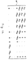
- each input variable can be fuzzified into five membership functions, as illustrated in Fig. 9. It should be noted that a different number of membership functions can be employed such as 4, 6 or 7.
- the membership functions are selected to be triangular, and are such that an input has a nonzero value for at most two membership functions simultaneously.
- the membership functions are as follows:
- the output sets in the preferred embodiment also include five membership functions, as illustrated in Fig. 10.
- FAi(j,k,t) FAi(j,k,t-1) + alphaI(j) * FOi(j,k,t) where: FAi is the fuzzy accumulator output for the integral term and FOi is the fuzzy tuner output for the integral term.
- the alphaP and alphaI terms each take a proportion of its associated fuzzy tuner output and add that to the fuzzy accumulator. This step is intended to make the tuning process more stable.
- Kp(j,k,t) FAp(j,k,t) * MaxPGain(j) * COVERAGE(j,k)
- Ki(j,k,t) FAi(j,k,t) * MaxIGain(j) * COVERAGE(j,k)
- Kd(j,k,t) FAi(j,k,t) * MaxDGain(j) * COVERAGE(j,k)
- COVERAGE(j,k) is set to .20 for all keys for all colors.
- the actual values of plate coverage for each ink key zone if available, can be used to achieve faster convergence.
- the FAi term is used in the calculation of Kd.
- a separate FAd term can be determined, using a FOd term as an output of the inference rules.
- d_Kp(j,k,t) alphaP(j) * FOp(j,k,t)* MaxPGain(j)* COVERAGE(j,k)
- d_Ki(j,k,t) alphaI(j) * FOi(j,k,t)* MaxIGain(j)* COVERAGE(j,k)
- d_Kd(j,k,t) alphaI(j) * FOi(j,k,t)* MaxDGain(j)* COVERAGE(j,k)
- the initial values of Kp, Ki, Kd can be determined by the known Ziegler-Nichols method.
- an input set including six membership functions instead of five can be defined.
- the six input membership functions could be the same as the five membership functions previously defined, with the exception that ZE is divided into two functions, termed PZE (positive zero) and NZE (negative zero).
- PZE positive zero
- NZE negative zero
- the fuzzy logic adaptive controller 216 could use the following inference rules:
- the effective ink key settings from the PID controller 212 can be used to directly control the ink keys, or can be further processed by the decoupling computation unit 220 to generate adjusted or actual ink key settings.
- the problem of ink key coupling is due to the spread of ink by the movement of the vibrator rollers. If the controller 204 determines that the ink flow to a particular ink key zone should be increased, because the increased ink amount spreads to adjacent ink key zones, increasing the ink flow to one zone will also increase the ink flow to neighboring zones. In order to compensate for this, the ink flow to neighboring keys must be decreased. This will have an effect on the neighboring ink keys as well.
- One side of a web has 24 ink key zones, which correspond to 24 SID measurements.
- One method to implement the system is to wait until all 24 SID measurements are obtained, and then change all 24 ink key readings at once. However, this method is slow.
- Another way to implement the system is to change an ink key immediately after the corresponding SID measurement is obtained, without accounting for the effects of neighboring ink keys. In this case, the method will eventually stabilize, but it does not take into account the effects of neighboring ink keys.
- An ink key distribution function or ink key spread function can be determined which represents the spread of ink from a source of ink which is the width of an ink key zone.
- the ink key spread function can be represented by a vector whose elements are representative of ink amounts in a corresponding zone.
- Vector V is obtained by averaging the experimentally obtained data over the width corresponding to each ink key zone, and then scaling so that the addition of all vector elements adds up to 1.
- the elements in vector V can then be interpreted as the fraction of ink which is distributed to a specific ink key zone.
- Each ink key results in its own distribution of ink, which is proportional to the ink key opening.
- 46% of the ink provided by a given ink key is passed directly into its corresponding ink key zone, 20% is passed to the immediate neighboring zones, and 4% is passed to the next set of neighbors, and so on.
- the decoupling computation unit 220 of Fig. 1 The effects of the vibrator rollers are taken into account by the decoupling computation unit 220 of Fig. 1. Mathematically, this is a deconvolution in which one seeks to find the ink key settings given an ink key distribution function and the effective ink key settings. In the preferred embodiment of the color control system 200, the SID measurements for respective ink key zones reach the PID loop serially in time rather than all at once.
- E S A
- E a vector representing the effective ink key openings
- A a vector representing the actual ink key openings
- S an ink key spread matrix, determined from vector V.
- E and A are both a 24 by 1 element vectors.
- S is a 24 by 24 element matrix. (The size is determined by the fact that there are 24 ink keys on the Harris M1000B press). If the ink spread is invariant across the ink keys, then matrix S is a Toeplitz matrix, that is, a matrix in which each row is a shifted version of the row above. Each row contains the elements of the vector V.
- Matrix S is illustrated in Fig. 11.
- inverted matrix S -1 may be slightly ill-conditioned. This means that the matrix may amplify noise. Additionally, the inverted matrix includes entries in each of the 24 columns. Thus to multiply E by a row of S -1 requires the use of all 24 entries.
- M -1 approximates an inverse spread function.
- M -1 is a symmetric matrix, and the numbers used to derive this matrix are .518, .196 and .045. In other words, for any ink key zone, it is assumed that 51.8% of the ink remains in that zone, 19.6% goes to immediate neighbors, and 4.5% goes to the neighbors two zones away.
- M -1 instead of S -1 , because there are at most 5 entries in a row of M -1 , it is necessary to obtain at most 5 SID measurements at a given time before an ink key change can be implemented.
- the numbers .518, .196 and .045 are a particular set of spread coefficients that will produce convergence of the control loop.
- Use of the matrix M -1 may introduce edge effects in the calculated ink key settings for the ink keys on each end.
- the edge effects are due to the fact that at an end, an increased ink amount for an ink key will affect the amount of ink fed to the adjacent keys on one side only.
- One approach to more accurately computing the ink key settings for the ink keys on the ends may be accomplished by modifying the element values in the matrix M -1 . For example, the ink that theoretically would be fed to a side of the web is accounted for by including that amount in the amount of ink fed to the end ink key zone. In other words, the element in the first row, first column of M -1 would be increased by adding [(.196 + .045)/.518].
- the element in the second row, first column of M -1 would be increased by adding (.045/.518).
- the ink key settings for the affected ink key settings on the other side of the web would be taken into account by modifying the elements in the last column of the last and second to last rows.
- the element in the last row, last column would be increased by adding [(.196 + .045)/.518].
- the element in the second to last row, last column would be increased by adding (.045/.518).
- Various other refinements are possible to account for edge effects.
- control loop operates with the following constraints: if the measured SID value is within .1 of the desired SID value, then the PID controller 216 operates without using the fuzzy logic parameter tuner 212 to tune the PID gain parameters, because of concern that the rule set is not optimized at that range. Additionally, there is a dead band zone. For example, if the SID value is within .07 of the desired SID value, the PID controller 216 does not operate to make further adjustments to the ink key settings.
- both the ink key settings and the ratchet assembly rotation angle control the amount of ink fed to the respective ink key zones, it is possible to change the ink key settings and/or the ratchet setting R in the ratchet assembly.
- any ratchet setting is acceptable.
- Ratchet settings which are too low may require ink key openings which are beyond the physical limits of the ink key.
- setting the ratchet too high leads to very low ink key openings, and a greater sensitivity of ink film thickness to changes in ink key opening. This reduces the precision in the ink key opening.
- the optimal condition is met when the ratchet setting is as low as possible without forcing the ink key openings beyond a certain fraction of the physical limit. This fraction is necessary to allow room for subsequent adjustment.
- the control algorithm may call for an ink key setting which is beyond the physical limits of an ink key.
- the requested ink key setting may be for an opening greater than 100%, or for a setting which is negative.
- requested ink key openings which are out of range are merely clipped, so that they do not go beyond the extreme values.
- the correction is straightforward. If, for example, the requested ink key opening is 120%, the current ratchet setting must be increased to at least 1.2 times its current value. In this case, the new ink key opening would be set to 100%. Alternatively, it may be preferred to increase the ratchet setting 10% higher in order to allow for some further range of adjustment.
- the above color control system was designed to be implemented in conjunction with a Telecolor II type ink fountain.
- a Telecolor II type ink fountain for example, the above color control system was designed to be implemented in conjunction with a Telecolor II type ink fountain.
- such a system will also be useful in connection with other ink fountains.
Landscapes
- Engineering & Computer Science (AREA)
- Quality & Reliability (AREA)
- Inking, Control Or Cleaning Of Printing Machines (AREA)
Applications Claiming Priority (2)
| Application Number | Priority Date | Filing Date | Title |
|---|---|---|---|
| US6503797P | 1997-11-10 | 1997-11-10 | |
| US65037P | 1997-11-10 |
Publications (2)
| Publication Number | Publication Date |
|---|---|
| EP0922580A2 true EP0922580A2 (de) | 1999-06-16 |
| EP0922580A3 EP0922580A3 (de) | 2000-03-29 |
Family
ID=22059937
Family Applications (1)
| Application Number | Title | Priority Date | Filing Date |
|---|---|---|---|
| EP98309181A Withdrawn EP0922580A3 (de) | 1997-11-10 | 1998-11-10 | Farbkontrollsystem für eine Druckmaschine |
Country Status (2)
| Country | Link |
|---|---|
| EP (1) | EP0922580A3 (de) |
| JP (1) | JPH11207931A (de) |
Cited By (3)
| Publication number | Priority date | Publication date | Assignee | Title |
|---|---|---|---|---|
| DE102008058964A1 (de) * | 2008-11-25 | 2010-05-27 | Robert Bosch Gmbh | Verfahren zur Regelung einer Bearbeitungsmaschine mit wenigstens einer Regeleinrichtung |
| US10976263B2 (en) | 2016-07-20 | 2021-04-13 | Ball Corporation | System and method for aligning an inker of a decorator |
| US11034145B2 (en) | 2016-07-20 | 2021-06-15 | Ball Corporation | System and method for monitoring and adjusting a decorator for containers |
Families Citing this family (1)
| Publication number | Priority date | Publication date | Assignee | Title |
|---|---|---|---|---|
| JP4641352B2 (ja) * | 2001-02-23 | 2011-03-02 | 大日本印刷株式会社 | インキ壺 |
Family Cites Families (6)
| Publication number | Priority date | Publication date | Assignee | Title |
|---|---|---|---|---|
| CH509159A (de) * | 1969-11-07 | 1971-06-30 | Koenig & Bauer Schnellpressfab | Verfahren zur Voreinstellung von Zonenschrauben an Farbwerken von Rotationsdruckmaschinen und Vorrichtung zur Durchführung des Verfahrens |
| US4655135A (en) * | 1981-10-16 | 1987-04-07 | Harris Graphics Corporation | Adaptive control system for press presetting |
| CH653618A5 (fr) * | 1983-06-21 | 1986-01-15 | Bobst Sa | Procede et dispositif pour maintenir constante la densite d'une couleur imprimee. |
| US5218555A (en) * | 1989-11-27 | 1993-06-08 | Toyo Boseki Kabushiki Kaisha | Method for judging a color difference using rules fuzzy inference and apparatus therefor |
| DE4212575A1 (de) * | 1991-04-20 | 1992-10-22 | Intech Pev Informationstechnis | Arbeitsmaschine mit der einstellung und optimierung des arbeitsergebnisses dienenden eingabestationen |
| US5724259A (en) * | 1995-05-04 | 1998-03-03 | Quad/Tech, Inc. | System and method for monitoring color in a printing press |
-
1998
- 1998-11-10 JP JP10318917A patent/JPH11207931A/ja active Pending
- 1998-11-10 EP EP98309181A patent/EP0922580A3/de not_active Withdrawn
Cited By (3)
| Publication number | Priority date | Publication date | Assignee | Title |
|---|---|---|---|---|
| DE102008058964A1 (de) * | 2008-11-25 | 2010-05-27 | Robert Bosch Gmbh | Verfahren zur Regelung einer Bearbeitungsmaschine mit wenigstens einer Regeleinrichtung |
| US10976263B2 (en) | 2016-07-20 | 2021-04-13 | Ball Corporation | System and method for aligning an inker of a decorator |
| US11034145B2 (en) | 2016-07-20 | 2021-06-15 | Ball Corporation | System and method for monitoring and adjusting a decorator for containers |
Also Published As
| Publication number | Publication date |
|---|---|
| EP0922580A3 (de) | 2000-03-29 |
| JPH11207931A (ja) | 1999-08-03 |
Similar Documents
| Publication | Publication Date | Title |
|---|---|---|
| US6142078A (en) | Adaptive color control system and method for regulating ink utilizing a gain parameter and sensitivity adapter | |
| EP0881076B2 (de) | Steuerungssystem von Farbzufuhreinstellelementen in einer Druckmaschine | |
| US6318260B1 (en) | Ink key control in a printing press including lateral ink spread, ink saturation, and back-flow compensation | |
| US6230622B1 (en) | Image data-oriented printing machine and method of operating the same | |
| DE4214139C2 (de) | Verfahren zur Feuchtmittelregulierung beim Drucken von einem Formzylinder in einer Offsetdruckmaschine | |
| EP0585740B1 (de) | Verfahren zur Steuerung des Druckprozesses auf einer autotypisch arbeitenden Druckmaschine, insbesondere Bogenoffsetdruckmaschine | |
| US6477954B1 (en) | Ink key presetting system for offset printing machines | |
| EP1083047B1 (de) | Verfahren und Vorrichtung zur Steuerung der Farbführungsmenge in einer mehrfarbigen Druckmaschine | |
| EP0922580A2 (de) | Farbkontrollsystem für eine Druckmaschine | |
| EP1245388B1 (de) | Verfahren zum Zuführen von Feuchtwasser in eine Druckmaschine | |
| US4972774A (en) | Automatically controlling water feedrate on a lithographic press | |
| JPS6054849A (ja) | インキ装置への湿し水供給を領域毎に測定技術的に制御する装置 | |
| US6679171B2 (en) | Method of controlling an ink layer on a printing form of a printing machine | |
| CN113942301B (zh) | 跨机器的颜色预调设配置 | |
| Englund et al. | Ink flow control by multiple models in an offset lithographic printing process | |
| GB2283940A (en) | Printing press process controller | |
| US6668723B2 (en) | Method for regulating the ink-to-wetting agent equilibrium in a rotary offset printing machine | |
| JP7473219B2 (ja) | オフセット輪転機の印刷システムおよびオフセット輪転機 | |
| JPH081914A (ja) | インキ供給量のプリセット装置 | |
| US6655272B2 (en) | Dampening control method taking account of a plurality of variables that influence the printing process | |
| JP3434177B2 (ja) | 色調早期安定化方法及び装置 | |
| US20210402754A1 (en) | Fountain solution thickness measurement using print engine response | |
| JPH11245381A (ja) | 印刷紙面の横方向印刷濃度制御装置 | |
| Englund et al. | Combining traditional and neural-based techniques for ink feed control in a newspaper printing press | |
| JP3121999B2 (ja) | 印刷インキの供給方法 |
Legal Events
| Date | Code | Title | Description |
|---|---|---|---|
| PUAI | Public reference made under article 153(3) epc to a published international application that has entered the european phase |
Free format text: ORIGINAL CODE: 0009012 |
|
| AK | Designated contracting states |
Kind code of ref document: A2 Designated state(s): BE DE DK FI FR GB IT NL |
|
| AX | Request for extension of the european patent |
Free format text: AL;LT;LV;MK;RO;SI |
|
| PUAL | Search report despatched |
Free format text: ORIGINAL CODE: 0009013 |
|
| AK | Designated contracting states |
Kind code of ref document: A3 Designated state(s): AT BE CH CY DE DK ES FI FR GB GR IE IT LI LU MC NL PT SE |
|
| AX | Request for extension of the european patent |
Free format text: AL;LT;LV;MK;RO;SI |
|
| 17P | Request for examination filed |
Effective date: 20000731 |
|
| STAA | Information on the status of an ep patent application or granted ep patent |
Free format text: STATUS: THE APPLICATION HAS BEEN WITHDRAWN |
|
| AKX | Designation fees paid |
Free format text: BE DE DK FI FR GB IT NL |
|
| 18W | Application withdrawn |
Withdrawal date: 20001013 |