EP0922349B1 - Communications network - Google Patents
Communications network Download PDFInfo
- Publication number
- EP0922349B1 EP0922349B1 EP97935692A EP97935692A EP0922349B1 EP 0922349 B1 EP0922349 B1 EP 0922349B1 EP 97935692 A EP97935692 A EP 97935692A EP 97935692 A EP97935692 A EP 97935692A EP 0922349 B1 EP0922349 B1 EP 0922349B1
- Authority
- EP
- European Patent Office
- Prior art keywords
- network
- packet
- directed
- node
- trail
- Prior art date
- Legal status (The legal status is an assumption and is not a legal conclusion. Google has not performed a legal analysis and makes no representation as to the accuracy of the status listed.)
- Expired - Lifetime
Links
Images


Classifications
-
- H—ELECTRICITY
- H04—ELECTRIC COMMUNICATION TECHNIQUE
- H04Q—SELECTING
- H04Q11/00—Selecting arrangements for multiplex systems
- H04Q11/0001—Selecting arrangements for multiplex systems using optical switching
- H04Q11/0005—Switch and router aspects
-
- H—ELECTRICITY
- H04—ELECTRIC COMMUNICATION TECHNIQUE
- H04L—TRANSMISSION OF DIGITAL INFORMATION, e.g. TELEGRAPHIC COMMUNICATION
- H04L45/00—Routing or path finding of packets in data switching networks
- H04L45/02—Topology update or discovery
-
- H—ELECTRICITY
- H04—ELECTRIC COMMUNICATION TECHNIQUE
- H04L—TRANSMISSION OF DIGITAL INFORMATION, e.g. TELEGRAPHIC COMMUNICATION
- H04L45/00—Routing or path finding of packets in data switching networks
- H04L45/16—Multipoint routing
-
- H—ELECTRICITY
- H04—ELECTRIC COMMUNICATION TECHNIQUE
- H04Q—SELECTING
- H04Q11/00—Selecting arrangements for multiplex systems
- H04Q11/0001—Selecting arrangements for multiplex systems using optical switching
- H04Q11/0005—Switch and router aspects
- H04Q2011/0007—Construction
- H04Q2011/0024—Construction using space switching
-
- H—ELECTRICITY
- H04—ELECTRIC COMMUNICATION TECHNIQUE
- H04Q—SELECTING
- H04Q11/00—Selecting arrangements for multiplex systems
- H04Q11/0001—Selecting arrangements for multiplex systems using optical switching
- H04Q11/0005—Switch and router aspects
- H04Q2011/0007—Construction
- H04Q2011/0033—Construction using time division switching
-
- H—ELECTRICITY
- H04—ELECTRIC COMMUNICATION TECHNIQUE
- H04Q—SELECTING
- H04Q11/00—Selecting arrangements for multiplex systems
- H04Q11/0001—Selecting arrangements for multiplex systems using optical switching
- H04Q11/0005—Switch and router aspects
- H04Q2011/0037—Operation
- H04Q2011/0039—Electrical control
-
- H—ELECTRICITY
- H04—ELECTRIC COMMUNICATION TECHNIQUE
- H04Q—SELECTING
- H04Q11/00—Selecting arrangements for multiplex systems
- H04Q11/0001—Selecting arrangements for multiplex systems using optical switching
- H04Q11/0005—Switch and router aspects
- H04Q2011/0052—Interconnection of switches
-
- H—ELECTRICITY
- H04—ELECTRIC COMMUNICATION TECHNIQUE
- H04Q—SELECTING
- H04Q11/00—Selecting arrangements for multiplex systems
- H04Q11/0001—Selecting arrangements for multiplex systems using optical switching
- H04Q11/0062—Network aspects
- H04Q2011/0073—Provisions for forwarding or routing, e.g. lookup tables
-
- H—ELECTRICITY
- H04—ELECTRIC COMMUNICATION TECHNIQUE
- H04Q—SELECTING
- H04Q11/00—Selecting arrangements for multiplex systems
- H04Q11/0001—Selecting arrangements for multiplex systems using optical switching
- H04Q11/0062—Network aspects
- H04Q2011/009—Topology aspects
Definitions
- the present invention relates to a communications network, and in particular to the routing of packets in a network.
- Some network topologies allow "one-dimensional" routing. For example, in a unidirectional ring the source simply places a packet onto the ring and the packet eventually reaches its destination without requiring any routing decision by intermediate nodes.
- One-dimensional routing may also be used, for example, on buses or rings with bi-directional links.
- one dimensional routing offers a number of attractive features, it suffers a serious limitation in that there is poor scaling of the relative routing efficiency and maximum throughput of the network as the number of nodes in the network is increased.
- multi-dimensional networks may be used.
- the main advantage of using a multi-dimensional network is that there is a multiplicity of paths available between any pair of nodes on the network. It is therefore possible to adopt a routing method that selects the shortest available path, and such a method in general will have a higher relative routing efficiency and a higher value for the maximum throughput.
- existing methods of routing on multi-dimensional networks have their own serious drawbacks. Because the routing methods can select from a multiplicity of paths through the network it is possible for two or more packets to attempt to occupy the same link simultaneously. The method therefore needs to be capable of resolving the contention that arises in this case.
- a method of routing a packet in a communications network which comprises a multiplicity of nodes ) and links which are configured as a multiplicity of directed trails which in combination span every node of the network, the method comprising:
- the present invention provides a fundamentally new approach to packet routing in multi-dimensional communications networks. It potentially offers all the advantage of one-dimensional routing, whilst overcoming the crucial disadvantage of poor scalability of routing efficiency and of the maximum throughput. It also completely avoids the need for contention resolution within the network.
- Preferred implementations of the invention offer the advantages of very simple processing and routing nodes which may be based on simple header-word recognition. Message delivery time is dominated by the speed of light delay. No contention is required within the network, there is no need for buffering within the network and the network is free of deadlock or livelock. Nodes in the network can be named in an arbitrary fashion. Networks embodying the present invention offer efficient routing and good throughput and these advantages are maintained as the method is scaled for larger networks. Using the invention, there is zero delay variation and packets can be delivered in the correct sequence.
- the invention can support both connectionless (datagram) and connection-orientated modes and in connection-orientated mode provides guaranteed bandwidth. The method also makes physical-layer broadcasting practical.
- the method includes reading the destination address at each node traversed by the packet.
- the only processing required at the node is that needed to determine whether or not the packet address matches the node address.
- each intermediate node forwards a packet which is received at the intermediate node and which is addressed to another node in a direction which is predetermined and independent of any information carried by the packet.
- An important advantage of the present invention is that it enables intermediate nodes to function without requiring any processing of the packet beyond that necessary to determine whether or not the packet destination address corresponds to the node address.
- the present invention is by not means limited in applicability to systems operating in the optical domain, it does offer special advantages when used with ultrafast photonic networks. It enables efficient use of the bandwidth offered by such networks, while avoiding the disadvantages of using deflection routing or the technological problems associated with the provision of optical buffers.
- each directed trail in the network is a subgraph of at least one closed directed trial and consists of a directed cycle or union of a plurality of connected directed cycles from a link-disjoint directed-cycle decomposition of the network.
- a timing sequence for the prescheduled switching of intermediate nodes comprises a frame divided into a plurality of time slots, and a source node outputs a packet onto the network in a selected one of the plurality of time slots within the timing frame, and the length of the link between successive nodes in a trial is such that a packet leaving one node in a first time slot arrives at the next successive node in a second time slot.
- the packet may be advanced or retarded by one time slot as it passes from one node to the next.
- a communications network a multiplicity of nodes and links which are configured as a multiplicity of directed trails which in combination span every node of the network and which include at least one directed trail linking each source node and each destination node in the network; the network further comprising means for selecting a directed trail T from the multiplicity of directed trails in dependence upon the destination of a packet, the selected trail T including the source node and destination node of the packet; and means for outputting the packet at the source node onto the selected one of the multiplicity of directed trails.
- the present invention also encompasses multiprocessor computer systems, local area networks, metropolitan area networks, campus networks and communications switches using networks in accordance with the preceding aspects of the invention.
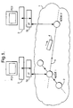
- An optical communications network comprises a LAN 1 linking a number of personal computer workstations 3. Each workstation is connected to the LAN via a network interface 3a. The workstations and LAN together provide a distributed computing environment which may be used, for example, for the visualisation of complex data. Each workstation is connected to a respective node 2 of the network. Packets of data 4 are communicated between the workstations 3 via the nodes 2 and links 5. In this example, the links 5 are formed from optical fibre and transmit the packets 4 in the optical domain.
- the network may comprise many hundreds of nodes.
- the nodes and the interconnecting fibres are configured as an nxn torus network.
- the n ⁇ n torus network is a regular network with unidirectional links, and the nodes have indegree and outdegree of 2.
- the links form a grid on the surface of a torus, and all the links in the n rows or n columns are codirectional.
- An example of a 4 ⁇ 4 network is shown in Fig. 4 .
- Each node contains a 2 ⁇ 2 'crossbar' switch or its logical equivalent. In the cross configuration the switch connects the input column to the output column, and the input row to the output row; in the bar configuration the input column is connected to the output row, and the input row is connected to the output column.
- Figure 8(a) shows the situation in which all switches are set to the cross position.
- the network consists of a set of 2 n cycles, each of length n .
- This link-disjoint directed-cycle decomposition of the network graph is well suited to the routing method of the present invention.
- a different cycle-decomposition of the network is obtained when all the switches are set to the bar position, as shown in Fig. 8(b) ; in that case the network consists of n cycles, each of length 2 n .
- this cycle decomposition is less well suited to directed-trail routing because a directed trail leading between a source-destination pair may, necessarily, be the union of many cycles.
- the switching operations that maintain a packet on its selected trail leading from its source to its destination can operate in an automatic fashion, without requiring the intermediate nodes to interrogate the packet destination address or to perform any intelligent route selection.
- the network operates in a slotted fashion with packets constrained to some maximum length, i.e. time is divided into a regular time slots which are dimensioned to contain a packet of the maximum allowable size together with a guard band.
- the crossbar switches in all the routing nodes in the network are arranged to operate in a regular, coherent fashion, locked to a global network clock at the time-slot rate. When the switches change configuration they do so during the guard band so as not to corrupt packets.
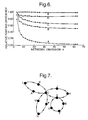
- Figure 9 is a time diagram showing the packet time slots, each of length T, arranged in frames of length n time slots.
- the crossbar switches are all set in the cross position (denoted c in the diagram); in the final time slot of the frame the switches are all set to the bar position (denoted b ).
- the length of each link connecting a pair of adjacent nodes in the network is selected and controlled so that the signal group time-of-flight is equal to ( qn + 1 - ⁇ ) T, where q is any integer, and ⁇ is the phase difference between the clock signals at the two nodes, expressed as a fraction of the time slot period T .
- the length of every link in the network is equal to an arbitrary integer number of frames plus one time slot.
- a packet which exits from a node in the j th time slot of a frame will arrive at the next node in the ( j +1)th time slot of a frame.
- the packet may be advanced or retarded by a fixed integer number of time slots.
- the packet may be advanced/retarded by any fixed integer number of slots which is not a multiple of n, if n is odd, or by a number which is odd if n is even.
- the only processing operation that a network node is required to perform on incoming packets is simple: the destination address of every incoming packet is examined, and if it corresponds to the address of the node the packet is removed from the network, otherwise it is forwarded.
- the process of comparing the packet address and the node address is a simple single-word matching operation, and can be performed at high speed; for example, optical recognition of 6-bit address words has been demonstrated recently at a peak rate of 100 Gbit/s [11]. Since the directed-trail routing does not use an algorithm that relies on any particular sequential numbering system for the network nodes, the nodes can be labelled in an entirely arbitrary fashion. This can simplify the tasks of planning, administrating and evolving the network.
- connectionless mode a source can transmit to a chosen destination by inserting packets in a vacant time slot corresponding to a directed trail that leads to the destination. There are no guarantees on the availability of suitable vacant time slots, and communication between the source and destination is transitory.
- connection-oriented mode prior signalling is used to reserve a regular sequence of suitable time slots allowing a connection to be established between a source-destination pair.
- broadcasting from a given source to every other node in the network can be achieved in a straightforward fashion; a packet which is to be broadcast is copied by each node as it traverses the network.
- broadcasting is not efficient if physical-layer mechanisms are used alone.
- transport-layer protocols can be highly effective in low-speed networks, for very high-speed networking the additional delays may be unacceptable.
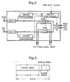
- Figure 2 shows the structure of a 2-connected node suitable for insertion in the MSN shown in Figure 4 .
- the heavy lines shown in Figure 2 are optical fibre paths.
- the delay units at the two inputs to the node provide the necessary adjustment on the lengths of the two incoming links to satisfy the requirement described earlier, that on each link connecting a pair of nodes, the signal group time-of-flight along the link should be equal to ( qn +1- ⁇ ) T, where q is any integer, and ⁇ is the phase difference between the clock signals at the two nodes, expressed as a fraction of the time slot period T.
- Each delay unit could consist of a combination of: i) a length of fibre cut to a suitable length to provide coarse timing adjustment; ii) a step-adjustable delay line consisting of a chain of 2x2 space switches and fibre delays (such as described in ref [12]) to provide timing adjustment to within a few hundred picoseconds; and iii) a free-space adjustable optical delay line (such as optical delay line type ODL-300-15-SMF manufactured by Santec Corporation) to provide fine adjustment to within a few tens of picoseconds.
- drifts in the optical path length of the incoming links may be caused by environmental factor acting on the fibre - for example, movement causing stretch, or temperature variations.
- This continuous environmental compensation can be achieved by detecting a variation in the relative timing of incoming packet arrivals and the time-slot clock at the node, and providing an electrical feedback control signal to the step-adjustable delay line and the free-space adjustable delay line units.
- the header-processing units performs the following tasks: i) detects the presence or absence of a packet in a time slot; ii) detects the time of arrival of a packet; and iii) determines whether or not an incoming packet is addressed to the node. For tasks i) and ii) it is sufficient to use a ⁇ 1 GHz-bandwidth photodetector to detect a fraction of the packet signal. The presence of a signal from this photodetector during the time slot indicates the presence of a packet.
- a suitable AND gate is a semiconductor optical amplifier supporting four-wave mixing (FWM).
- the basic space-switching operation is performed by the three crossbar switches.
- the reason for 3 switches rather than only 1 is that this provides the signal paths needed to connect to and from a local host computer system.
- Suitable space switches capable of operation in a time of 1 ns or less are lithium niobate devices such as type Y-35-8772-02 supplied by GEC Advanced Components.
- the space switches in the node are activated by the electronic switch controller unit shown in Figure 2 which acts on the basis of the following information: i) whether or not the position of the time slot in the frame corresponds to a 'cross' or 'bar' configuration in the directed-trail routing cycle (1 bit); ii) whether or not an incoming packet occupies the current time slot (1 bit per input port); iii) whether or not the destination address for an incoming packet matches the address of the node (1 bit per input port); iv) whether or not a packet that is waiting in the host's output buffer wishes to access an output port in the current time slot (1 bit per output port).
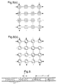
- the various curves are:A, hamiltonian-cycle routing in nxn torus network;B, directed-trail routing in nxn torus network; C, directed-trail routing in nxn MSN; D, dead-reckoning routing in nxn MSN; E,routing in nxn MSN using a routing rule that provides a shortest-path route (Maxemchuk's "first rule"[5]). It can be seen that methods B and C implementing the present invention maintain a relatively high efficiency of 60% or greater as the network size is scaled upwards. The efficiency is markedly greater than hamiltonian-cycle routing which is a one-dimensional routing technique applicable to a torus network.
- Figure 16 shows an N ⁇ N buffered packet switch, in which the interconnect 160 is a network embodying the invention.
- Figure 17 shows a multiprocessor computer in which processors, memory, file stores and I/O ports are connected to respective nodes of a network employing directed-trail routing.
- the packet itself carries no routing information, apart from its destination address, and intermediate nodes between the source and destination perform no routing function in reaction to the packet.
- the only processing operation that network nodes are required to perform on incoming packets is simple: at every node n k in G , the destination address of every incoming packet is examined; if the packet destination address corresponds to the address of n k the packet is removed from the network, otherwise it is forwarded.
- Mechanisms ensure that a packet, once despatched by its source onto a chosen trail, will be forwarded along that trail until removed at the packet destination.
- the operation of these mechanisms at all nodes is entirely independent from the presence or absence of any packet or packet content.
- an eulerian digraph is the union of a set of link-disjoint directed cycles (a directed cycle being a closed alternating sequence of nodes and links, in which each link is a directed link from the immediately-preceding node to the immediately-following node, and all the links and nodes are distinct).
- This set is a link-disjoint directed-cycle decomposition of G , denoted D ( G ).
- any open trail in G is a subgraph of at least one closed trail consisting of a cycle, or the union of several connected cycles, from D ( G ).
- the shortest open trail from A to B namely ACDEFB
- the closed trail CKLACDEFBDHJC which is the union of the connected cycles CKLAC, CDHJC and DEFBD .
- Cutpoints in the closed trails occur at every connecting point of the component cycles. Rearrangement of the internal connections between inward and outward links at the various cutpoints cause different trails to be selected.
- Directed trail routing offers many of the advantages of one-dimensional routing while overcoming the limited efficiency of such techniques.
- One-dimensional routing may be carried out in one-dimensional networks-e.g. single-directional or bi-directional busses or rings-or using hamiltonian cycles.
- the source node selects the entire trail from the source to the destination before sending the packet.
- Intermediate nodes need perform no routing function in reaction to a packet, and this greatly simplifies the design of the nodes. This also eliminates contention within the transmission path; this removes the necessity for contention resolution using internal network buffers or deflection-routing strategies, which introduce delay variations and can undesirably rearrange a packet sequence.
- the source is located at the intersection of row sr and column sc ; similarly the destination is located at the intersection of row dr and column dc . If, for example, sr is even and sc is odd, the source node orientation is called 'up and right'.
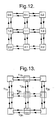
- Figure 12 shows a two-dimensional 3x3 mesh with bidirectional links. This is an example of a network which is symmetric in the graphical sense (defined earlier) because for every link there is a corresponding link with the opposite orientation, forming a symmetric pair.
- Each node contains a space switch that can be configured in the cross or bar position.
- Figure 13 shows the configuration of the network when all the switches are in the cross position. In this case, the network is composed of a set of closed trails ( T 1h , T 1v , and so on), each trail consisting of the union of cycles formed from symmetric pairs.
- Figure 14 shows the configuration when all the switches are in the bar position.
Landscapes
- Engineering & Computer Science (AREA)
- Computer Networks & Wireless Communication (AREA)
- Signal Processing (AREA)
- Data Exchanges In Wide-Area Networks (AREA)
- Use Of Switch Circuits For Exchanges And Methods Of Control Of Multiplex Exchanges (AREA)
- Telephonic Communication Services (AREA)
Applications Claiming Priority (3)
| Application Number | Priority Date | Filing Date | Title |
|---|---|---|---|
| GB9617907 | 1996-08-28 | ||
| GBGB9617907.2A GB9617907D0 (en) | 1996-08-28 | 1996-08-28 | Communications network |
| PCT/GB1997/002160 WO1998009403A2 (en) | 1996-08-28 | 1997-08-12 | Communications network |
Publications (2)
| Publication Number | Publication Date |
|---|---|
| EP0922349A2 EP0922349A2 (en) | 1999-06-16 |
| EP0922349B1 true EP0922349B1 (en) | 2008-10-22 |
Family
ID=10799007
Family Applications (1)
| Application Number | Title | Priority Date | Filing Date |
|---|---|---|---|
| EP97935692A Expired - Lifetime EP0922349B1 (en) | 1996-08-28 | 1997-08-12 | Communications network |
Country Status (9)
Families Citing this family (67)
| Publication number | Priority date | Publication date | Assignee | Title |
|---|---|---|---|---|
| US6631018B1 (en) | 1997-08-27 | 2003-10-07 | Nortel Networks Limited | WDM optical network with passive pass-through at each node |
| DE69841787D1 (de) * | 1997-09-17 | 2010-09-09 | British Telecomm | Prozessverwaltunssystem in einem computernetzwerk |
| SE9904685D0 (sv) * | 1999-12-17 | 1999-12-17 | Switchcore Ab | A programmable packet decoder |
| JP4629307B2 (ja) * | 2001-02-24 | 2011-02-09 | インターナショナル・ビジネス・マシーンズ・コーポレーション | トーラス・ネットワークおよびツリー・ネットワークでの算術機能 |
| US7617302B1 (en) * | 2001-11-02 | 2009-11-10 | Nortel Networks Limited | Communication networks |
| US7315517B2 (en) * | 2002-05-22 | 2008-01-01 | Board Of Supervisors Of Louisiana State University And Agricultural And Mechanical College | Non-blocking WDM optical networks |
| US7881239B2 (en) | 2004-03-27 | 2011-02-01 | Dust Networks, Inc. | Low-powered autonomous radio node with temperature sensor and crystal oscillator |
| US8194655B2 (en) * | 2004-08-05 | 2012-06-05 | Dust Networks, Inc. | Digraph based mesh communication network |
| US8059629B1 (en) | 2004-03-27 | 2011-11-15 | Dust Networks, Inc. | Digraph network timing synchronization |
| WO2005096722A2 (en) * | 2004-03-27 | 2005-10-20 | Dust Networks | Digraph based mesh communication network |
| US7961664B1 (en) | 2004-03-27 | 2011-06-14 | Dust Networks, Inc. | Digraph network subnetworks |
| US7420980B1 (en) * | 2004-03-27 | 2008-09-02 | Dust Networks, Inc. | Digraph network superframes |
| US20060002341A1 (en) * | 2004-06-30 | 2006-01-05 | Yigal Bejerano | Methods and devices for scheduling the transmission of packets in configurable access wireless networks that provide Quality-of-Service guarantees |
| JP4422595B2 (ja) * | 2004-11-26 | 2010-02-24 | 富士通株式会社 | 監視システム,被監視装置,監視装置,及び監視方法 |
| JP4291281B2 (ja) * | 2005-02-03 | 2009-07-08 | 富士通株式会社 | 情報処理システム、計算ノード、情報処理システムの制御方法 |
| US7826379B2 (en) * | 2005-02-07 | 2010-11-02 | International Business Machines Corporation | All-to-all sequenced fault detection system |
| US8495411B2 (en) * | 2005-02-07 | 2013-07-23 | International Business Machines Corporation | All row, planar fault detection system |
| US7529963B2 (en) * | 2005-02-07 | 2009-05-05 | International Business Machines Corporation | Cell boundary fault detection system |
| US7506197B2 (en) * | 2005-02-07 | 2009-03-17 | International Business Machines Corporation | Multi-directional fault detection system |
| US7437595B2 (en) * | 2005-02-07 | 2008-10-14 | International Business Machines Corporation | Row fault detection system |
| US7451342B2 (en) * | 2005-02-07 | 2008-11-11 | International Business Machines Corporation | Bisectional fault detection system |
| WO2007096852A1 (en) * | 2006-02-21 | 2007-08-30 | University College Cork - National University Of Ireland, Cork | An optical communication network |
| US20080022079A1 (en) * | 2006-07-24 | 2008-01-24 | Archer Charles J | Executing an allgather operation with an alltoallv operation in a parallel computer |
| US8165025B2 (en) * | 2006-12-08 | 2012-04-24 | Ixia | Method and apparatus for generating a unique packet identifier |
| US8140826B2 (en) * | 2007-05-29 | 2012-03-20 | International Business Machines Corporation | Executing a gather operation on a parallel computer |
| US8161480B2 (en) * | 2007-05-29 | 2012-04-17 | International Business Machines Corporation | Performing an allreduce operation using shared memory |
| US8122228B2 (en) * | 2008-03-24 | 2012-02-21 | International Business Machines Corporation | Broadcasting collective operation contributions throughout a parallel computer |
| US7991857B2 (en) * | 2008-03-24 | 2011-08-02 | International Business Machines Corporation | Broadcasting a message in a parallel computer |
| US8422402B2 (en) * | 2008-04-01 | 2013-04-16 | International Business Machines Corporation | Broadcasting a message in a parallel computer |
| JP5104489B2 (ja) * | 2008-04-03 | 2012-12-19 | 日本電気株式会社 | 分散イベント検出システム、分散イベント検出方法、及び分散イベント検出用プログラム |
| US8375197B2 (en) * | 2008-05-21 | 2013-02-12 | International Business Machines Corporation | Performing an allreduce operation on a plurality of compute nodes of a parallel computer |
| US8161268B2 (en) * | 2008-05-21 | 2012-04-17 | International Business Machines Corporation | Performing an allreduce operation on a plurality of compute nodes of a parallel computer |
| US8484440B2 (en) | 2008-05-21 | 2013-07-09 | International Business Machines Corporation | Performing an allreduce operation on a plurality of compute nodes of a parallel computer |
| US8281053B2 (en) | 2008-07-21 | 2012-10-02 | International Business Machines Corporation | Performing an all-to-all data exchange on a plurality of data buffers by performing swap operations |
| US8565089B2 (en) * | 2010-03-29 | 2013-10-22 | International Business Machines Corporation | Performing a scatterv operation on a hierarchical tree network optimized for collective operations |
| US8332460B2 (en) | 2010-04-14 | 2012-12-11 | International Business Machines Corporation | Performing a local reduction operation on a parallel computer |
| US9424087B2 (en) | 2010-04-29 | 2016-08-23 | International Business Machines Corporation | Optimizing collective operations |
| US8346883B2 (en) | 2010-05-19 | 2013-01-01 | International Business Machines Corporation | Effecting hardware acceleration of broadcast operations in a parallel computer |
| US8489859B2 (en) | 2010-05-28 | 2013-07-16 | International Business Machines Corporation | Performing a deterministic reduction operation in a compute node organized into a branched tree topology |
| US8949577B2 (en) | 2010-05-28 | 2015-02-03 | International Business Machines Corporation | Performing a deterministic reduction operation in a parallel computer |
| US8776081B2 (en) | 2010-09-14 | 2014-07-08 | International Business Machines Corporation | Send-side matching of data communications messages |
| JP2012094975A (ja) * | 2010-10-25 | 2012-05-17 | Fujitsu Telecom Networks Ltd | 光パケットスイッチ装置 |
| US8566841B2 (en) | 2010-11-10 | 2013-10-22 | International Business Machines Corporation | Processing communications events in parallel active messaging interface by awakening thread from wait state |
| US8893083B2 (en) | 2011-08-09 | 2014-11-18 | International Business Machines Coporation | Collective operation protocol selection in a parallel computer |
| US8910178B2 (en) | 2011-08-10 | 2014-12-09 | International Business Machines Corporation | Performing a global barrier operation in a parallel computer |
| US9246627B2 (en) * | 2011-08-17 | 2016-01-26 | Nec Laboratories America, Inc. | Joint optimization procedure for routing and wavelength assignment with combined dedicated shared protections in multi-cable multi-fiber optical WDM networks |
| US9495135B2 (en) | 2012-02-09 | 2016-11-15 | International Business Machines Corporation | Developing collective operations for a parallel computer |
| US9111151B2 (en) * | 2012-02-17 | 2015-08-18 | National Taiwan University | Network on chip processor with multiple cores and routing method thereof |
| EP2665212B1 (en) * | 2012-05-16 | 2016-11-30 | Alcatel Lucent | Optical data transmission system |
| US9661405B2 (en) * | 2013-05-10 | 2017-05-23 | Huawei Technologies Co., Ltd. | System and method for photonic switching |
| WO2017000282A1 (zh) * | 2015-07-01 | 2017-01-05 | 冯旋宇 | 路由器中数据定向发送的方法及路由器 |
| CN105099901A (zh) * | 2015-07-01 | 2015-11-25 | 冯旋宇 | 路由器中数据定向发送的方法及路由器 |
| US10574727B2 (en) * | 2015-10-21 | 2020-02-25 | Honeywell International Inc. | MIB data broadcast using inexpensive method incorporating microcontroller and FPGA |
| CN109617800B (zh) * | 2019-01-18 | 2021-06-01 | 福建师范大学 | 一种基于平衡超立方体的数据中心网络容错安全路由方法 |
| CN111475330B (zh) * | 2020-03-10 | 2023-03-28 | 长安大学 | 基于Harary图生成树的FRSH码的系统、构造及故障节点修复方法 |
| US10903904B1 (en) | 2020-07-08 | 2021-01-26 | Eci Telecom Ltd. | Systems and methods for configuring a communications network |
| US10904131B1 (en) | 2020-07-08 | 2021-01-26 | Eci Telecom Ltd. | Systems and methods for configuring a communications network |
| EP4179714B1 (en) * | 2020-07-08 | 2025-04-02 | ECI Telecom Ltd. | Systems and methods for configuring a communications network |
| US12353988B2 (en) | 2020-07-09 | 2025-07-08 | Celestial Ai Inc. | Neuromorphic photonics with coherent linear neurons |
| KR102725305B1 (ko) | 2020-08-06 | 2024-11-01 | 셀레스티얼 에이아이 인코포레이티드 | 결맞음 광 컴퓨팅 아키텍처 |
| US12271595B2 (en) | 2022-03-18 | 2025-04-08 | Celestial Ai Inc. | Photonic memory fabric for system memory interconnection |
| US20220405562A1 (en) | 2021-06-18 | 2022-12-22 | Celestial Ai Inc. | Electro-photonic network for machine learning |
| US20230296838A1 (en) * | 2022-03-18 | 2023-09-21 | Celestial Ai Inc. | Circuit package for connecting to an electro-photonic memory fabric |
| KR20240155370A (ko) | 2022-03-18 | 2024-10-28 | 셀레스티얼 에이아이 인코포레이티드 | 광 멀티 다이 상호 연결 브리지(omib) |
| US12283584B2 (en) | 2022-07-26 | 2025-04-22 | Celestial Ai Inc. | Electrical bridge package with integrated off-bridge photonic channel interface |
| US12191257B2 (en) | 2022-07-26 | 2025-01-07 | Celestial Ai Inc. | Electrical bridge package with integrated off-bridge photonic channel interface |
| US12217056B2 (en) | 2023-01-27 | 2025-02-04 | Celestial Ai Inc. | Load/store unit for a tensor engine and methods for loading or storing a tensor |
Family Cites Families (19)
| Publication number | Priority date | Publication date | Assignee | Title |
|---|---|---|---|---|
| US5021947A (en) * | 1986-03-31 | 1991-06-04 | Hughes Aircraft Company | Data-flow multiprocessor architecture with three dimensional multistage interconnection network for efficient signal and data processing |
| US4873517A (en) | 1988-06-23 | 1989-10-10 | International Business Machines Corporation | Method for selecting least weight end node to end node route in a data communications network |
| US5103447A (en) * | 1988-09-02 | 1992-04-07 | Hitachi, Ltd. | High-speed ring LAN system |
| US5490232A (en) | 1990-10-25 | 1996-02-06 | Daiwa House Industry Co., Ltd. | Computer-aided thought process simulation design system |
| US5297137A (en) * | 1991-01-30 | 1994-03-22 | International Business Machines Corporation | Process for routing data packets around a multi-node communications network |
| DE69233333T2 (de) * | 1991-11-29 | 2005-02-17 | Nec Corp. | Optisches-ATM-Selbstlenkungsvermittlungssystem mit einer verringerten Zellenkopfbitanzahl |
| US5561790A (en) | 1992-03-24 | 1996-10-01 | International Business Machines Corporation | Shortest path determination processes for use in modeling systems and communications networks |
| US5477444A (en) | 1992-09-14 | 1995-12-19 | Bhat; Naveen V. | Control system using an adaptive neural network for target and path optimization for a multivariable, nonlinear process |
| US5664066A (en) | 1992-11-09 | 1997-09-02 | The United States Of America As Represented By The United States Department Of Energy | Intelligent system for automatic feature detection and selection or identification |
| CA2115876A1 (en) | 1993-03-22 | 1994-09-23 | Henry Alexander Kautz | Methods and apparatus for constraint satisfaction |
| US5383164A (en) | 1993-06-10 | 1995-01-17 | The Salk Institute For Biological Studies | Adaptive system for broadband multisignal discrimination in a channel with reverberation |
| US5524176A (en) | 1993-10-19 | 1996-06-04 | Daido Steel Co., Ltd. | Fuzzy expert system learning network |
| US5455854A (en) | 1993-10-26 | 1995-10-03 | Taligent, Inc. | Object-oriented telephony system |
| US5509123A (en) | 1994-03-22 | 1996-04-16 | Cabletron Systems, Inc. | Distributed autonomous object architectures for network layer routing |
| US5559707A (en) | 1994-06-24 | 1996-09-24 | Delorme Publishing Company | Computer aided routing system |
| US5586219A (en) | 1994-09-30 | 1996-12-17 | Yufik; Yan M. | Probabilistic resource allocation system with self-adaptive capability |
| DE19528563C2 (de) | 1995-08-03 | 1997-11-06 | Siemens Ag | Verfahren zur Bewertung von mindestens zwei mehrteiligen Kommunikationsverbindungen zwischen zwei Kommunikationspartnern in einem Mehrknotennetzwerk |
| US5684800A (en) * | 1995-11-15 | 1997-11-04 | Cabletron Systems, Inc. | Method for establishing restricted broadcast groups in a switched network |
| US6078946A (en) * | 1996-09-10 | 2000-06-20 | First World Communications, Inc. | System and method for management of connection oriented networks |
-
1996
- 1996-08-28 GB GBGB9617907.2A patent/GB9617907D0/en active Pending
-
1997
- 1997-08-12 CA CA002264395A patent/CA2264395C/en not_active Expired - Fee Related
- 1997-08-12 US US09/029,197 patent/US6714552B1/en not_active Expired - Lifetime
- 1997-08-12 AU AU38586/97A patent/AU733625B2/en not_active Ceased
- 1997-08-12 JP JP10511352A patent/JP2000517125A/ja active Pending
- 1997-08-12 EP EP97935692A patent/EP0922349B1/en not_active Expired - Lifetime
- 1997-08-12 WO PCT/GB1997/002160 patent/WO1998009403A2/en active Application Filing
- 1997-08-12 DE DE69739060T patent/DE69739060D1/de not_active Expired - Lifetime
- 1997-08-12 CN CN97199202.9A patent/CN1235722A/zh active Pending
Also Published As
| Publication number | Publication date |
|---|---|
| EP0922349A2 (en) | 1999-06-16 |
| JP2000517125A (ja) | 2000-12-19 |
| WO1998009403A2 (en) | 1998-03-05 |
| WO1998009403A3 (en) | 1998-05-07 |
| US6714552B1 (en) | 2004-03-30 |
| GB9617907D0 (en) | 1996-10-09 |
| DE69739060D1 (de) | 2008-12-04 |
| CA2264395C (en) | 2006-10-10 |
| AU733625B2 (en) | 2001-05-17 |
| AU3858697A (en) | 1998-03-19 |
| CA2264395A1 (en) | 1998-03-05 |
| CN1235722A (zh) | 1999-11-17 |
Similar Documents
| Publication | Publication Date | Title |
|---|---|---|
| EP0922349B1 (en) | Communications network | |
| EP0761071B1 (en) | Optical telecommunications network | |
| AU712810B2 (en) | Packet routing | |
| AU753148B2 (en) | Communications network | |
| EP0842473B1 (en) | Multiple level minimum logic network | |
| Yu et al. | Analysis of a dual-receiver node with high fault tolerance for ultrafast OTDM packet-switched shuffle networks | |
| Cotter et al. | Ultrafast all-optical signal processing for packet switching | |
| Palnati et al. | Deadlock-free routing in an optical interconnect for high-speed wormhole routing networks | |
| Rodrigues et al. | Performance assessment of signaling protocols in optical burst switching mesh networks | |
| Cotter et al. | ‘Dead reckoning’—a primitive and efficient self-routing protocol for ultrafast mesh networks | |
| Choi et al. | On wavelength assignment in WDM optical networks | |
| Yoon et al. | B-banyan and B-delta networks for multiprocessor systems | |
| Nam | Multihop Local Lightwave Network | |
| Chlamtac et al. | Toward optical packet-switched network architectures | |
| Scheideler | Protocols for all-optical networks | |
| HK1013584B (en) | Optical telecommunications network | |
| AU5652000A (en) | Multiple level minimum logic network | |
| HK1010926B (en) | Multiple level minimum logic network |
Legal Events
| Date | Code | Title | Description |
|---|---|---|---|
| PUAI | Public reference made under article 153(3) epc to a published international application that has entered the european phase |
Free format text: ORIGINAL CODE: 0009012 |
|
| 17P | Request for examination filed |
Effective date: 19990222 |
|
| AK | Designated contracting states |
Kind code of ref document: A2 Designated state(s): BE DE ES FR GB IT NL |
|
| 17Q | First examination report despatched |
Effective date: 20041210 |
|
| REG | Reference to a national code |
Ref country code: HK Ref legal event code: WD Ref document number: 1021098 Country of ref document: HK |
|
| GRAP | Despatch of communication of intention to grant a patent |
Free format text: ORIGINAL CODE: EPIDOSNIGR1 |
|
| GRAS | Grant fee paid |
Free format text: ORIGINAL CODE: EPIDOSNIGR3 |
|
| GRAA | (expected) grant |
Free format text: ORIGINAL CODE: 0009210 |
|
| AK | Designated contracting states |
Kind code of ref document: B1 Designated state(s): BE DE ES FR GB IT NL |
|
| REG | Reference to a national code |
Ref country code: GB Ref legal event code: FG4D |
|
| REF | Corresponds to: |
Ref document number: 69739060 Country of ref document: DE Date of ref document: 20081204 Kind code of ref document: P |
|
| NLV1 | Nl: lapsed or annulled due to failure to fulfill the requirements of art. 29p and 29m of the patents act | ||
| PG25 | Lapsed in a contracting state [announced via postgrant information from national office to epo] |
Ref country code: ES Free format text: LAPSE BECAUSE OF FAILURE TO SUBMIT A TRANSLATION OF THE DESCRIPTION OR TO PAY THE FEE WITHIN THE PRESCRIBED TIME-LIMIT Effective date: 20090202 |
|
| PG25 | Lapsed in a contracting state [announced via postgrant information from national office to epo] |
Ref country code: NL Free format text: LAPSE BECAUSE OF FAILURE TO SUBMIT A TRANSLATION OF THE DESCRIPTION OR TO PAY THE FEE WITHIN THE PRESCRIBED TIME-LIMIT Effective date: 20081022 |
|
| PG25 | Lapsed in a contracting state [announced via postgrant information from national office to epo] |
Ref country code: BE Free format text: LAPSE BECAUSE OF FAILURE TO SUBMIT A TRANSLATION OF THE DESCRIPTION OR TO PAY THE FEE WITHIN THE PRESCRIBED TIME-LIMIT Effective date: 20081022 |
|
| PLBE | No opposition filed within time limit |
Free format text: ORIGINAL CODE: 0009261 |
|
| STAA | Information on the status of an ep patent application or granted ep patent |
Free format text: STATUS: NO OPPOSITION FILED WITHIN TIME LIMIT |
|
| PG25 | Lapsed in a contracting state [announced via postgrant information from national office to epo] |
Ref country code: IT Free format text: LAPSE BECAUSE OF FAILURE TO SUBMIT A TRANSLATION OF THE DESCRIPTION OR TO PAY THE FEE WITHIN THE PRESCRIBED TIME-LIMIT Effective date: 20081022 |
|
| 26N | No opposition filed |
Effective date: 20090723 |
|
| PGFP | Annual fee paid to national office [announced via postgrant information from national office to epo] |
Ref country code: DE Payment date: 20110823 Year of fee payment: 15 Ref country code: FR Payment date: 20110901 Year of fee payment: 15 |
|
| REG | Reference to a national code |
Ref country code: FR Ref legal event code: ST Effective date: 20130430 |
|
| PG25 | Lapsed in a contracting state [announced via postgrant information from national office to epo] |
Ref country code: DE Free format text: LAPSE BECAUSE OF NON-PAYMENT OF DUE FEES Effective date: 20130301 |
|
| PG25 | Lapsed in a contracting state [announced via postgrant information from national office to epo] |
Ref country code: FR Free format text: LAPSE BECAUSE OF NON-PAYMENT OF DUE FEES Effective date: 20120831 |
|
| REG | Reference to a national code |
Ref country code: DE Ref legal event code: R119 Ref document number: 69739060 Country of ref document: DE Effective date: 20130301 |
|
| PGFP | Annual fee paid to national office [announced via postgrant information from national office to epo] |
Ref country code: GB Payment date: 20160819 Year of fee payment: 20 |
|
| REG | Reference to a national code |
Ref country code: GB Ref legal event code: PE20 Expiry date: 20170811 |
|
| PG25 | Lapsed in a contracting state [announced via postgrant information from national office to epo] |
Ref country code: GB Free format text: LAPSE BECAUSE OF EXPIRATION OF PROTECTION Effective date: 20170811 |